Oxygen sensor INFINITI FX35 2008 Service Manual
[x] Cancel search | Manufacturer: INFINITI, Model Year: 2008, Model line: FX35, Model: INFINITI FX35 2008Pages: 3924, PDF Size: 81.37 MB
Page 288 of 3924

ON-VEHICLE SERVICEAT-215
< SERVICE INFORMATION >
DE
F
G H
I
J
K L
M A
B
AT
N
O P
ON-VEHICLE SERVICE
Control Valve with TCM and A/T Fluid Temperature Sensor 2INFOID:0000000001327393
COMPONENTS
CONTROL VALVE WITH TCM ASSEMB LY REMOVAL AND INSTALLATION
Removal
1. Disconnect the battery cable from the negative terminal.
2. Drain ATF through drain plug.
3. Remove front cross bar. Refer to FSU-6, "
Removal and Installation".
4. Disconnect heated oxygen sensor 2 harness connector.
5. Disconnect A/T assembly harness connector.
1. A/T 2. Snap ring 3. Sub-harness
4. Control valve with TCM 5. Bracket 6. A/T fluid temperature sensor 2
7. Oil pan gasket 8. Clip 9. Bracket (VK45DE)
10. Bracket (VK45DE) 11. Oil pan mounting bolt 12. Oil pan
13. Magnet 14. Drain plug 15. Drain plug gasket
16. Terminal cord assembly 17. O-ring
Refer to GI section to make sure icons (symbol marks) in the figure. Refer to GI-8, "
Component".
SCIA8045E
3AA93ABC3ACD3AC03ACA3AC03AC63AC53A913A773A893A873A873A8E3A773A983AC73AC93AC03AC3
3A893A873A873A8F3A773A9D3AAF3A8A3A8C3A863A9D3AAF3A8B3A8C
Page 296 of 3924

ON-VEHICLE SERVICEAT-223
< SERVICE INFORMATION >
DE
F
G H
I
J
K L
M A
B
AT
N
O P
c. Tighten oil pan mounting bolts to the specified torque in numeri- cal order shown in the figure after temporarily tightening them.
Refer to "COMPONENTS".
CAUTION:
Do not reuse oil pan mounting bolts.
16. Install drain plug to oil pan, and then tighten drain plug to the specified torque. Refer to "COMPONENTS".
CAUTION:
Do not reuse drain plug gasket.
17. Pull up A/T assembly harness connector. CAUTION:
Be careful not to damage connector.
18. Install snap ring to A/T assembly harness connector.
19. Connect A/T assembly harness connector.
20. Connect heated oxygen sensor 2 harness connector.
21. Install front cross bar. Refer to FSU-6, "
Removal and Installa-
tion".
22. Pour ATF into A/T assembly. Refer to AT- 11 , "
Changing A/T
Fluid".
23. Connect the battery cable to the negative terminal.
A/T FLUID TEMPERATURE SENSOR 2 REMOVAL AND INSTALLATION
Removal
1. Disconnect the battery cabl e from the negative terminal.
2. Remove front cross bar. Refer to FSU-6, "
Removal and Installation".
3. Disconnect heated oxygen sensor 2 harness connector.
4. Drain ATF through drain plug.
5. Remove bracket (1) (VK45DE), clips (2), oil pan (3) and oil pan gasket.
: Vehicle front
: Bolt (22)
Drain plug (4)
SCIA4113E
SCIA5038E
SCIA5039E
SCIA8128E
3AA93ABC3ACD3AC03ACA3AC03AC63AC53A913A773A893A873A873A8E3A773A983AC73AC93AC03AC3
3A893A873A873A8F3A773A9D3AAF3A8A3A8C3A863A9D3AAF3A8B3A8C
Page 299 of 3924
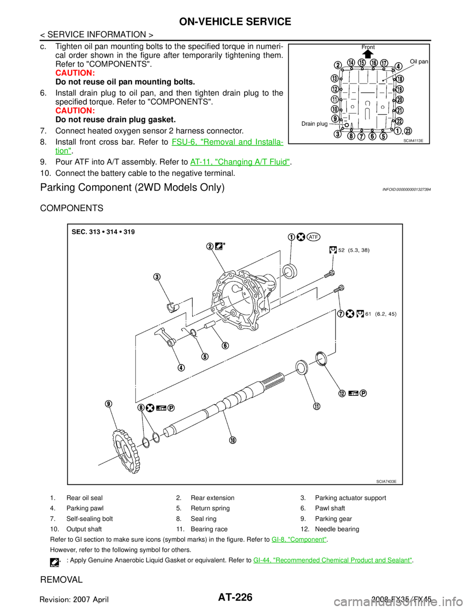
AT-226
< SERVICE INFORMATION >
ON-VEHICLE SERVICE
c. Tighten oil pan mounting bolts to the specified torque in numeri-cal order shown in the figure after temporarily tightening them.
Refer to "COMPONENTS".
CAUTION:
Do not reuse oil pan mounting bolts.
6. Install drain plug to oil pan, and then tighten drain plug to the specified torque. Refer to "COMPONENTS".
CAUTION:
Do not reuse drain plug gasket.
7. Connect heated oxygen sensor 2 harness connector.
8. Install front cross bar. Refer to FSU-6, "
Removal and Installa-
tion".
9. Pour ATF into A/T assembly. Refer to AT- 11 , "
Changing A/T Fluid".
10. Connect the battery cable to the negative terminal.
Parking Component (2WD Models Only)INFOID:0000000001327394
COMPONENTS
REMOVAL
SCIA4113E
1. Rear oil seal 2. Rear extension 3. Parking actuator support
4. Parking pawl 5. Return spring 6. Pawl shaft
7. Self-sealing bolt 8. Seal ring 9. Parking gear
10. Output shaft 11. Bearing race 12. Needle bearing
Refer to GI section to make sure icons (symbol marks) in the figure. Refer to GI-8, "
Component".
However, refer to the following symbol for others.
*: Apply Genuine Anaerobic Liquid Gasket or equivalent. Refer to GI-44, "Recommended Chemical Product and Sealant".
SCIA7433E
3AA93ABC3ACD3AC03ACA3AC03AC63AC53A913A773A893A873A873A8E3A773A983AC73AC93AC03AC3
3A893A873A873A8F3A773A9D3AAF3A8A3A8C3A863A9D3AAF3A8B3A8C
Page 410 of 3924

PRECAUTIONSATC-5
< SERVICE INFORMATION >
C
DE
F
G H
I
K L
M A
B
AT C
N
O P
Never release refrigerant into the air. Use appr oved recovery/recycling equipment to capture the
refrigerant every time an air co nditioning system is discharged.
Always wear eye and hand protection (goggles and gloves) when working with any refrigerant or air
conditioning system.
Never store or heat refrigerant containers above 52 °C (126 °F).
Never heat a refrigerant container with an open flame; if container warming is required, place the
bottom of the container in a warm pail of water.
Never intentionally drop, puncture, or incinerate refrigerant containers.
Keep refrigerant away from open flames: poison ous gas will be produced if refrigerant burns.
Refrigerant will displace oxygen, therefore be certa in to work in well ventilated areas to prevent suf-
focation.
Never pressure test or leak test HFC-134a (R-134a) service equipment and/or vehicle air conditioning
systems with compressed air during repair. Some mixtures of air and HFC-134a (R-134a) have been
shown to be combustible at elevat ed pressures. These mixtures, if ig nited, may cause injury or prop-
erty damage. Additional health a nd safety information may be obtain ed from refrigerant manufactur-
ers.
Precaution for Refrigerant ConnectionINFOID:0000000001328155
A new type refrigerant connection has been introduced to a ll refrigerant lines except the following location.
Expansion valve to evaporator
Refrigerant pressure sensor to condenser
ABOUT ONE-TOUCH JOINT
Description
One-touch joints are pipe joints which do not require tools during piping connection.
Unlike conventional connection methods using union nuts and flanges, controlling tightening torque at con-
nection point is not necessary.
When removing a pipe joint, use a disconnector.
COMPONENT PARTS
FUNCTIONS OF COMPONENT PARTS
NOTE:
1 Pipe (Male-side) Retains O-rings.
Retains garter spring in cage (A).
2 Garter spring Anchors female-side piping.
3 Indicator ring When connection is made properly, this is ejected from male-side piping. (This part is no longer nec-
essary after connection.)
4 O-ring Seals connection point. (Not reusable)
5 Pipe (Female-side) Seals connection by compressing O-rings.
Anchors piping connection using flare (B) and garter spring.
RJIA4383J
3AA93ABC3ACD3AC03ACA3AC03AC63AC53A913A773A893A873A873A8E3A773A983AC73AC93AC03AC3
3A893A873A873A8F3A773A9D3AAF3A8A3A8C3A863A9D3AAF3A8B3A8C
Page 1248 of 3924

EC-8
Component Inspection ...........................................545
ASCD INDICATOR ..........................................547
Component Description ....................................... ..547
CONSULT-III Reference Value in Data Monitor
Mode .................................................................... ..
547
Wiring Diagram ......................................................548
Diagnosis Procedure .............................................548
ELECTRICAL LOAD SIGNAL .........................550
Description ........................................................... ..550
CONSULT-III Reference Value in Data Monitor
Mode .................................................................... ..
550
Diagnosis Procedure .............................................550
FUEL INJECTOR .............................................552
Component Description ....................................... ..552
CONSULT-III Reference Value in Data Monitor
Mode .................................................................... ..
552
Wiring Diagram ......................................................553
Diagnosis Procedure .............................................554
Component Inspection ...........................................557
Removal and Installation .......................................557
FUEL PUMP .....................................................558
Description ........................................................... ..558
CONSULT-III Reference Value in Data Monitor
Mode .................................................................... ..
558
Wiring Diagram ......................................................559
Diagnosis Procedure .............................................560
Component Inspection ...........................................562
Removal and Installation .......................................562
ICC BRAKE SWITCH ......................................563
Component Description ....................................... ..563
CONSULT-III Reference Value in Data Monitor
Mode .................................................................... ..
563
Wiring Diagram ......................................................564
Diagnosis Procedure .............................................565
Component Inspection ...........................................567
IGNITION SIGNAL ...........................................569
Component Description ....................................... ..569
Wiring Diagram ......................................................570
Diagnosis Procedure .............................................575
Component Inspection ...........................................578
Removal and Installation .......................................580
REFRIGERANT PRESSURE SENSOR ..........581
Component Description ....................................... ..581
Wiring Diagram ......................................................582
Diagnosis Procedure .............................................583
Removal and Installation .......................................585
SNOW MODE SWITCH ...................................586
Description ........................................................... ..586
CONSULT-III Reference Value in Data Monitor
Mode .................................................................... ..
586
Wiring Diagram ......................................................587
Diagnosis Procedure .............................................587
Component Inspection ...........................................589
MIL AND DATA LINK CONNECTOR ...............591
Wiring Diagram .................................................... .591
SERVICE DATA AND SPECIFICATIONS
(SDS) ................................................................
593
Fuel Pressure ....................................................... .593
Idle Speed and Ignition Timing .............................593
Calculated Load Value ..........................................593
Mass Air Flow Sensor ...........................................593
Intake Air Temperature Sensor .............................593
Engine Coolant Temperature Sensor ...................593
Air Fuel Ratio (A/F) Sensor 1 Heater ....................593
Heated Oxygen sensor 2 Heater ..........................593
Crankshaft Position Sensor (POS) .......................594
Camshaft Position Sensor (PHASE) .....................594
Throttle Control Motor .......................................... .594
Fuel Injector ..........................................................594
Fuel Pump .............................................................594
VK45DE
SERVICE INFORMATION .. .......................
595
INDEX FOR DTC ............................................ ..595
DTC No. Index ..................................................... .595
Alphabetical Index .................................................598
PRECAUTIONS .............................................. ..603
Precaution for Supplemental Restraint System
(SRS) "AIR BAG" and "SEAT BELT PRE-TEN-
SIONER" .............................................................. .
603
Precaution for Procedure without Cowl Top Cover .603
On Board Diagnosis (OBD) System of Engine and
A/T ........................................................................
603
Precaution .............................................................604
PREPARATION ................................................607
Special Service Tool ............................................ .607
Commercial Service Tool ......................................608
ENGINE CONTROL SYSTEM ..........................609
Schematic ............................................................ .609
Multiport Fuel Injection (MFI) System ...................609
Electronic Ignition (EI) System ..............................612
Fuel Cut Control (at No Load and High Engine
Speed) ..................................................................
612
AIR CONDITIONING CUT CONTROL .............614
Input/Output Signal Chart .................................... .614
System Description ...............................................614
AUTOMATIC SPEED CONTROL DEVICE
(ASCD) ..............................................................
615
System Description .............................................. .615
Component Description ........................................616
CAN COMMUNICATION ..................................617
System Description .............................................. .617
EVAPORATIVE EMISSION SYSTEM ..............618
Description ........................................................... .618
Component Inspection ..........................................620
3AA93ABC3ACD3AC03ACA3AC03AC63AC53A913A773A893A873A873A8E3A773A983AC73AC93AC03AC3
3A893A873A873A8F3A773A9D3AAF3A8A3A8C3A863A9D3AAF3A8B3A8C
Page 1256 of 3924

EC-16
Description ...........................................................1182
CONSULT-III Reference Value in Data Monitor
Mode ....................................................................
1182
Wiring Diagram ....................................................1183
Diagnosis Procedure ...........................................1183
Component Inspection .........................................1185
VARIABLE INDUCTION AIR CONTROL SYS-
TEM (VIAS) .....................................................
1187
Description ...........................................................1187
CONSULT-III Reference Va lue in Data Monitor
Mode ....................................................................
1188
Wiring Diagram ....................................................1189
Diagnosis Procedure ...........................................1190
Component Inspection .........................................1193
Removal and Installation .....................................1193
MIL AND DATA LINK CONNECTOR .............1194
Wiring Diagram ....................................................1194
SERVICE DATA AND SPECIFICATIONS
(SDS) ..............................................................
1196
Fuel Pressure .......................................................1196
Idle Speed and Ignition Timing ............................1196
Calculated Load Value .........................................1196
Mass Air Flow Sensor ..........................................1196
Intake Air Temperature Sensor ............................1196
Engine Coolant Temperature Sensor ..................1196
Fuel Tank Temperature Sensor ...........................1196
Crankshaft Position Sensor (POS) ......................1197
Camshaft Position Sensor (PHASE) ....................1197
A/F Sensor 1 Heater ............................................1197
Heated Oxygen sensor 2 Heater .........................1197
Throttle Control Motor ..........................................1197
Fuel Injector .........................................................1197
Fuel Pump ............................................................1197
3AA93ABC3ACD3AC03ACA3AC03AC63AC53A913A773A893A873A873A8E3A773A983AC73AC93AC03AC3
3A893A873A873A8F3A773A9D3AAF3A8A3A8C3A863A9D3AAF3A8B3A8C
Page 1269 of 3924
![INFINITI FX35 2008 Service Manual
PREPARATIONEC-29
< SERVICE INFORMATION > [VQ35DE]
C
D
E
F
G H
I
J
K L
M A
EC
NP
O
PREPARATION
Special Service ToolINFOID:0000000001325893
The actual shapes of Kent-Moore t
ools may differ from those](/img/42/57017/w960_57017-1268.png "INFINITI FX35 2008 Service Manual
PREPARATIONEC-29
< SERVICE INFORMATION > [VQ35DE]
C
D
E
F
G H
I
J
K L
M A
EC
NP
O
PREPARATION
Special Service ToolINFOID:0000000001325893
The actual shapes of Kent-Moore t
ools may differ from those")
PREPARATIONEC-29
< SERVICE INFORMATION > [VQ35DE]
C
D
E
F
G H
I
J
K L
M A
EC
NP
O
PREPARATION
Special Service ToolINFOID:0000000001325893
The actual shapes of Kent-Moore t
ools may differ from those of special service tools illustrated here.
Tool number
(Kent-Moore No.)
Tool name Description
KV10117100
(J-36471-A)
Heated oxygen sensor
wrench Loosening or tightening heated oxygen sensor
with 22 mm (0.87 in) hexagon nut
KV10114400
(J-38365)
Heated oxygen sensor
wrench Loosening or tightening air fuel ratio (A/F) sensor
a: 22 mm (0.87 in)
(J-44321)
Fuel pressure gauge
kit Checking fuel pressure
(J-44321-6)
Fuel pressure adapter Connecting fuel pressure gauge to quick connec-
tor type fuel lines.
(J-44626)
Air fuel ratio (A/F)
sensor wrench Loosening or tightening air fuel ratio (A/F) sensor 1
(J-45488)
Quick connector re-
lease Remove fuel tube quick connectors in engine
room.
S-NT379
S-NT636
LEC642
LBIA0376E
LEM054
PBIC0198E
3AA93ABC3ACD3AC03ACA3AC03AC63AC53A913A773A893A873A873A8E3A773A983AC73AC93AC03AC3
3A893A873A873A8F3A773A9D3AAF3A8A3A8C3A863A9D3AAF3A8B3A8C
Page 1270 of 3924
![INFINITI FX35 2008 Service Manual
EC-30
< SERVICE INFORMATION >[VQ35DE]
PREPARATION
Commercial Service Tool
INFOID:0000000001325894
Tool name
(Kent-Moore No.) Description
Leak detector
i.e.: (J-41416) Locating EVAP leak
EVAP service](/img/42/57017/w960_57017-1269.png "INFINITI FX35 2008 Service Manual
EC-30
< SERVICE INFORMATION >[VQ35DE]
PREPARATION
Commercial Service Tool
INFOID:0000000001325894
Tool name
(Kent-Moore No.) Description
Leak detector
i.e.: (J-41416) Locating EVAP leak
EVAP service")
EC-30
< SERVICE INFORMATION >[VQ35DE]
PREPARATION
Commercial Service Tool
INFOID:0000000001325894
Tool name
(Kent-Moore No.) Description
Leak detector
i.e.: (J-41416) Locating EVAP leak
EVAP service port
adapter
i.e.: (J-41413-OBD) Applying positive pressure through EVAP service
port
Fuel filler cap adapter
i.e.: (MLR-8382) Checking fuel tank vacuum relief valve opening
pressure
Socket wrench Removing and installing engine coolant tempera- ture sensor
Oxygen sensor thread
cleaner
i.e.: (J-43897-18)
(J-43897-12) Reconditioning the exhaust system threads before
installing a new oxygen sensor. Use with anti-
seize lubricant shown below.
a: 18 mm diameter with pitch 1.5 mm for Zirco-
nia Oxygen Sensor
b: 12 mm diameter with pitch 1.25 mm for Tita-
nia Oxygen Sensor
Anti-seize lubricant
i.e.: (Permatex
TM
133AR or equivalent
meeting MIL specifica-
tion MIL-A-907) Lubricating oxygen sensor thread cleaning tool
when reconditioning exhaust system threads.
S-NT703
S-NT704
S-NT815
S-NT705
AEM488
S-NT779
3AA93ABC3ACD3AC03ACA3AC03AC63AC53A913A773A893A873A873A8E3A773A983AC73AC93AC03AC3
3A893A873A873A8F3A773A9D3AAF3A8A3A8C3A863A9D3AAF3A8B3A8C
Page 1272 of 3924
![INFINITI FX35 2008 Service Manual
EC-32
< SERVICE INFORMATION >[VQ35DE]
ENGINE CONTROL SYSTEM
*1: This sensor is not used to control the engine system under normal conditions.
*2: This signal is sent to the ECM through CAN communicat](/img/42/57017/w960_57017-1271.png "INFINITI FX35 2008 Service Manual
EC-32
< SERVICE INFORMATION >[VQ35DE]
ENGINE CONTROL SYSTEM
*1: This sensor is not used to control the engine system under normal conditions.
*2: This signal is sent to the ECM through CAN communicat")
EC-32
< SERVICE INFORMATION >[VQ35DE]
ENGINE CONTROL SYSTEM
*1: This sensor is not used to control the engine system under normal conditions.
*2: This signal is sent to the ECM through CAN communication line.
*3: ECM determines the start signal status by the signals of engine speed and battery voltage.
SYSTEM DESCRIPTION
The amount of fuel injected from the fuel injector is
determined by the ECM. The ECM controls the length of
time the valve remains open (injection pulse duration). T he amount of fuel injected is a program value in the
ECM memory. The program value is preset by engi ne operating conditions. These conditions are determined
by input signals (for engine speed and intake air) from both the crankshaft position sensor and the mass air
flow sensor.
VARIOUS FUEL INJECTION I NCREASE/DECREASE COMPENSATION
In addition, the amount of fuel injected is compens ated to improve engine performance under various operat-
ing conditions as listed below.
When starting the engine
During acceleration
Hot-engine operation
When selector lever is changed from N to D
High-load, high-speed operation
During high engine speed operation
MIXTURE RATIO FEEDBACK CONTROL (CLOSED LOOP CONTROL)
The mixture ratio feedback system prov ides the best air-fuel mixture ratio for driveability and emission control.
The three way catalyst 1 can then better reduce CO, HC and NOx emissions. This system uses air fuel ratio
Sensor Input Signal to ECM ECM function Actuator
Crankshaft position sensor (POS) Engine speed*
3
Piston position
Fuel injection
& mixture ratio
controlFuel injector
Camshaft position sensor (PHASE)
Mass air flow sensor Amount of intake air
Engine coolant temperature sensor Engine coolant temperature
Air fuel ratio (A/F) sensor 1 Density of oxygen in exhaust gas
Throttle position sensor Throttle position
Accelerator pedal position sensor Accelerator pedal position
Park/neutral position (PNP) switch Gear position
Knock sensor Engine knocking condition
Battery
Battery voltage*
3
Power steering pressure sensor Power steering operation
Heated oxygen sensor 2*
1Density of oxygen in exhaust gas
Air conditioner switch Air conditioner operation*
2
Wheel sensorVehicle speed*2
PBIB3020E
3AA93ABC3ACD3AC03ACA3AC03AC63AC53A913A773A893A873A873A8E3A773A983AC73AC93AC03AC3
3A893A873A873A8F3A773A9D3AAF3A8A3A8C3A863A9D3AAF3A8B3A8C
Page 1273 of 3924
![INFINITI FX35 2008 Service Manual
ENGINE CONTROL SYSTEMEC-33
< SERVICE INFORMATION > [VQ35DE]
C
D
E
F
G H
I
J
K L
M A
EC
NP
O
(A/F) sensor 1 in the exhaust manifold to monitor
whether the engine operation is rich or lean. The ECM
ad](/img/42/57017/w960_57017-1272.png "INFINITI FX35 2008 Service Manual
ENGINE CONTROL SYSTEMEC-33
< SERVICE INFORMATION > [VQ35DE]
C
D
E
F
G H
I
J
K L
M A
EC
NP
O
(A/F) sensor 1 in the exhaust manifold to monitor
whether the engine operation is rich or lean. The ECM
ad")
ENGINE CONTROL SYSTEMEC-33
< SERVICE INFORMATION > [VQ35DE]
C
D
E
F
G H
I
J
K L
M A
EC
NP
O
(A/F) sensor 1 in the exhaust manifold to monitor
whether the engine operation is rich or lean. The ECM
adjusts the injection pulse width according to the sensor voltage signal. For more information about air fuel
ratio (A/F) sensor 1, refer to EC-220
. This maintains the mixture ratio within the range of stoichiometric (ideal
air-fuel mixture).
This stage is referred to as the closed loop control condition.
Heated oxygen sensor 2 is located downstream of the thr ee way catalyst 1. Even if the switching characteris-
tics of air fuel ratio (A/F) sensor 1 shift, the air-fuel ratio is controlled to stoichiometric by the signal from
heated oxygen sensor 2.
Open Loop Control
The open loop system condition refers to when the ECM detects any of the following conditions. Feedback
control stops in order to maintain stabilized fuel combustion.
Deceleration and acceleration
High-load, high-speed operation
Malfunction of air fuel ratio (A/F) sensor 1 or its circuit
Insufficient activation of air fuel ratio (A /F) sensor 1 at low engine coolant temperature
High engine coolant temperature
During warm-up
After shifting from N to D
When starting the engine
MIXTURE RATIO SELF-LEARNING CONTROL
The mixture ratio feedback control system monitors the mixture ratio signal transmitted from air fuel ratio (A/F)
sensor 1. This feedback signal is then sent to the ECM. The ECM controls the basic mixture ratio as close to
the theoretical mixture ratio as possible. However, the bas ic mixture ratio is not necessarily controlled as orig-
inally designed. Both manufacturing differences (i.e., mass air flow sensor hot wire) and characteristic
changes during operation (i.e., fuel injector clogging) directly affect mixture ratio.
Accordingly, the difference between the basic and theoretical mixture ratios is monitored in this system. This is
then computed in terms of “injection pulse duration” to automatically compensate for the difference between
the two ratios.
“Fuel trim” refers to the feedback compensation value co mpared against the basic injection duration. Fuel trim
includes short term fuel trim and long term fuel trim.
“Short term fuel trim” is the short-term fuel compensati on used to maintain the mixture ratio at its theoretical
value. The signal from air fuel ratio (A/F) sensor 1 i ndicates whether the mixture ratio is RICH or LEAN com-
pared to the theoretical value. The signal then triggers a r eduction in fuel volume if the mixture ratio is rich, and
an increase in fuel volume if it is lean.
“Long term fuel trim” is overall fuel compensation ca rried out long-term to compensate for continual deviation
of the short term fuel trim from the central value. Such deviation will occur due to individual engine differences,
wear over time and changes in the usage environment.
FUEL INJECTION TIMING
Two types of systems are used.
Sequential Multiport Fuel Injection System
Fuel is injected into each cylinder during each engine cycl e according to the firing order. This system is used
when the engine is running.
Simultaneous Multiport Fuel Injection System
Fuel is injected simultaneously into all six cylinders twice each engine cycle. In other words, pulse signals of
the same width are simultaneously transmitted from the ECM.
The six fuel injectors will then receive the signals two times for each engine cycle.
This system is used when the engine is being started and/or if the fail-safe system (CPU) is operating.
SEF179U
3AA93ABC3ACD3AC03ACA3AC03AC63AC53A913A773A893A873A873A8E3A773A983AC73AC93AC03AC3
3A893A873A873A8F3A773A9D3AAF3A8A3A8C3A863A9D3AAF3A8B3A8C