STEERING WHEEL TILT MOTOR INFINITI FX35 2008 Service Manual
[x] Cancel search | Manufacturer: INFINITI, Model Year: 2008, Model line: FX35, Model: INFINITI FX35 2008Pages: 3924, PDF Size: 81.37 MB
Page 3654 of 3924
AUTOMATIC DRIVE POSITIONERSE-15
< SERVICE INFORMATION >
C
DE
F
G H
J
K L
M A
B
SE
N
O P
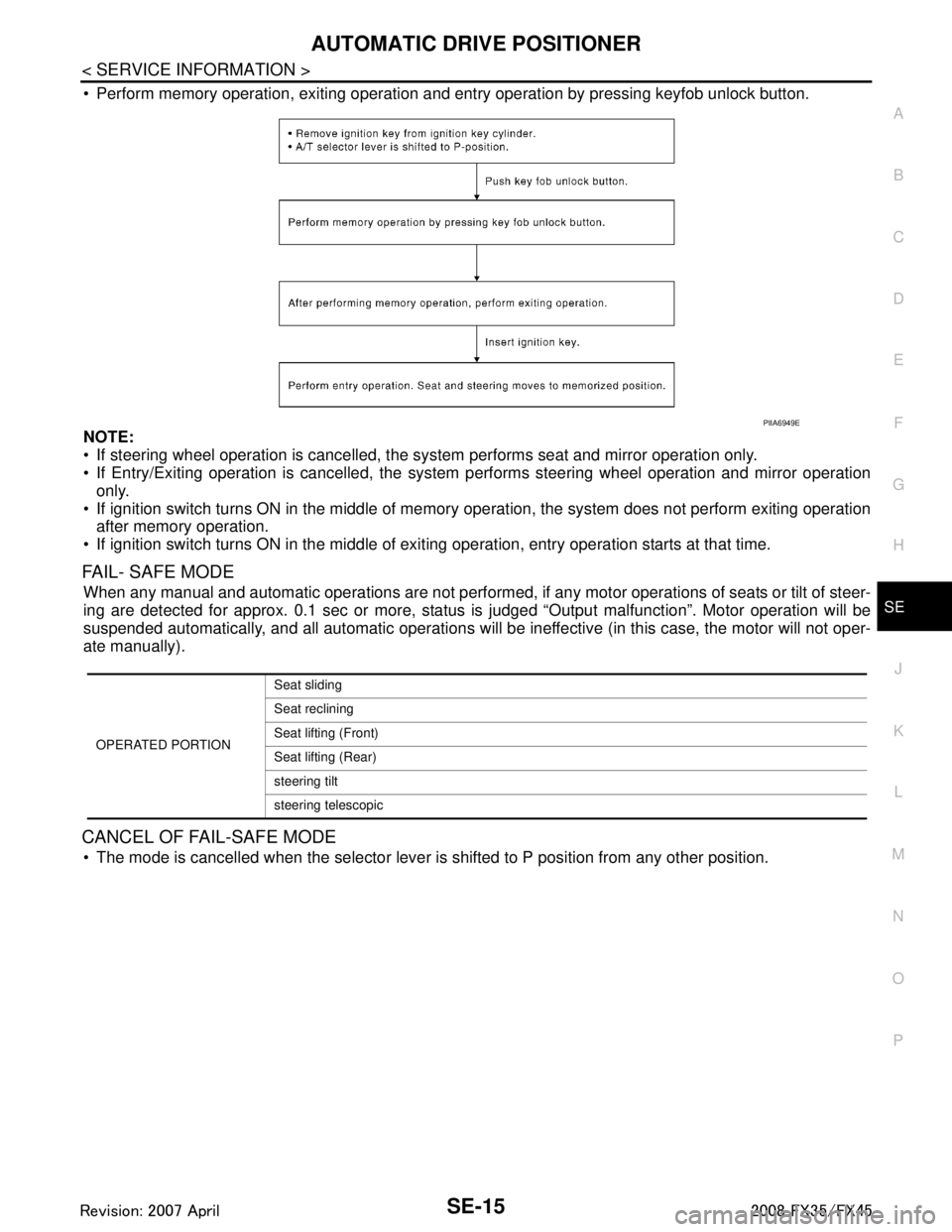
Perform memory operation, exiting operation and entry operation by pressing keyfob unlock button.
NOTE:
If steering wheel operation is cancelled, t he system performs seat and mirror operation only.
If Entry/Exiting operation is canc elled, the system performs steering wheel operation and mirror operation
only.
If ignition switch turns ON in the middle of memory operation, the system does not perform exiting operation
after memory operation.
If ignition switch turns ON in the middle of exit ing operation, entry operation starts at that time.
FAIL- SAFE MODE
When any manual and automatic operations are not performed, if any motor operations of seats or tilt of steer-
ing are detected for approx. 0.1 sec or more, status is judged “Output malfunction”. Motor operation will be
suspended automatically, and all automatic operations will be ineffective (in this case, the motor will not oper-
ate manually).
CANCEL OF FAIL-SAFE MODE
The mode is cancelled when the selector lever is shifted to P position from any other position.
PIIA6949E
OPERATED PORTIONSeat sliding
Seat reclining
Seat lifting (Front)
Seat lifting (Rear)
steering tilt
steering telescopic
3AA93ABC3ACD3AC03ACA3AC03AC63AC53A913A773A893A873A873A8E3A773A983AC73AC93AC03AC3
3A893A873A873A8F3A773A9D3AAF3A8A3A8C3A863A9D3AAF3A8B3A8C
Page 3688 of 3924
AUTOMATIC DRIVE POSITIONERSE-49
< SERVICE INFORMATION >
C
DE
F
G H
J
K L
M A
B
SE
N
O P
OK or NG
OK >> Steering telescopic motor circuit is OK.
NG >> GO TO 3.
3.CHECK TELESCOPIC MOTO R HARNESS CONTINUITY
1. Turn ignition switch OFF.
2. Disconnect automatic drive positioner control unit and tilt motor and telescopic motor connector.
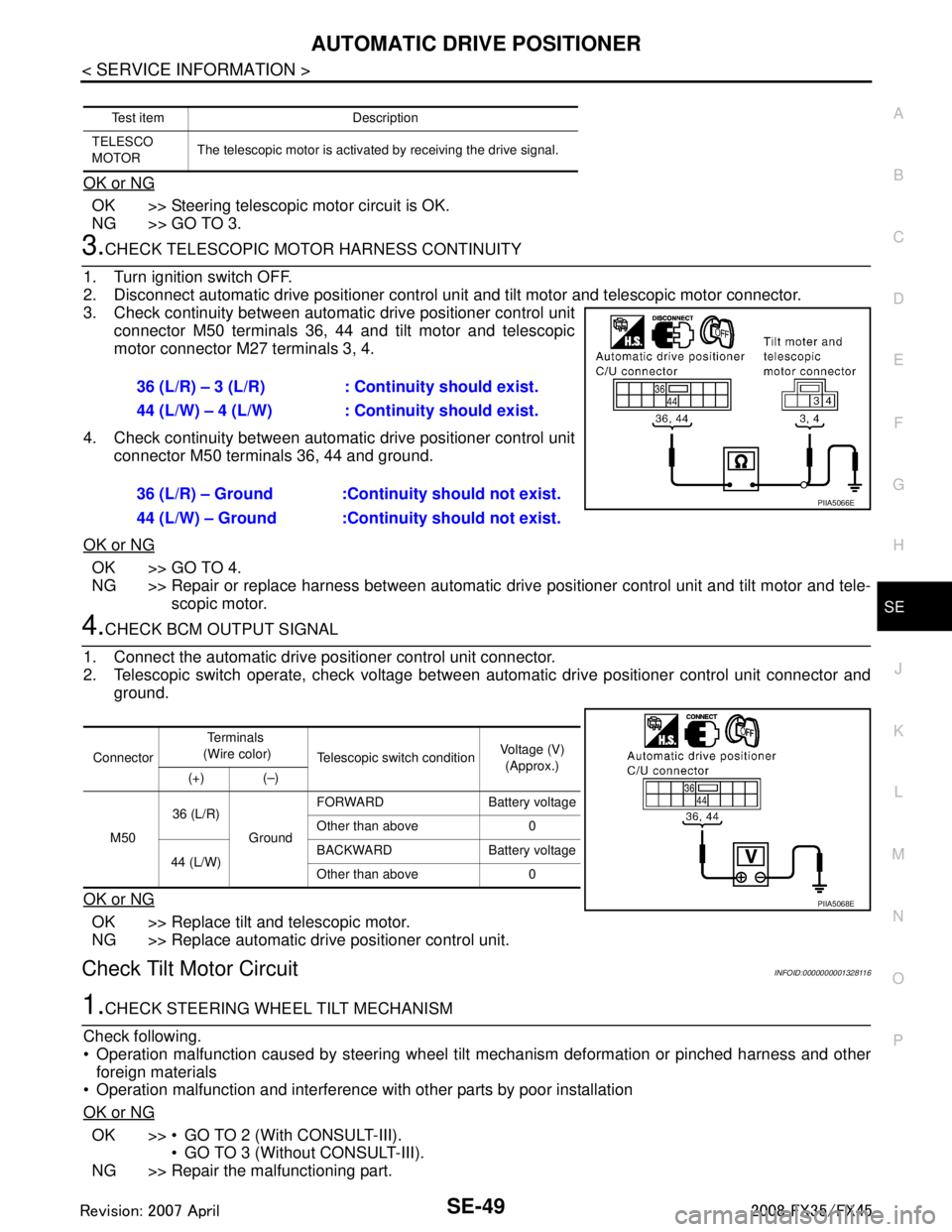
3. Check continuity between automat ic drive positioner control unit
connector M50 terminals 36, 44 and tilt motor and telescopic
motor connector M27 terminals 3, 4.
4. Check continuity between automat ic drive positioner control unit
connector M50 terminals 36, 44 and ground.
OK or NG
OK >> GO TO 4.
NG >> Repair or replace harness between automatic dr ive positioner control unit and tilt motor and tele-
scopic motor.
4.CHECK BCM OUTPUT SIGNAL
1. Connect the automatic drive positioner control unit connector.
2. Telescopic switch operate, check voltage between aut omatic drive positioner control unit connector and
ground.
OK or NG
OK >> Replace tilt and telescopic motor.
NG >> Replace automatic drive positioner control unit.
Check Tilt Motor CircuitINFOID:0000000001328116
1.CHECK STEERING WH EEL TILT MECHANISM
Check following.
Operation malfunction caused by steering wheel t ilt mechanism deformation or pinched harness and other
foreign materials
Operation malfunction and interference with other parts by poor installation
OK or NG
OK >> GO TO 2 (With CONSULT-III). GO TO 3 (Without CONSULT-III).
NG >> Repair the malfunctioning part.
Test item Description
TELESCO
MOTOR The telescopic motor is activated by receiving the drive signal.
36 (L/R) – 3 (L/R) : Co
ntinuity should exist.
44 (L/W) – 4 (L/W) : Co ntinuity should exist.
36 (L/R) – Ground :Continuity should not exist.
44 (L/W) – Ground :Continuity should not exist.
PIIA5066E
Connector Te r m i n a l s
(Wire color) Telescopic switch condition Voltage (V)
(Approx.)
(+) (–)
M50 36 (L/R)
GroundFORWARD Battery voltage
Other than above 0
44 (L/W) BACKWARD Battery voltage
Other than above 0
PIIA5068E
3AA93ABC3ACD3AC03ACA3AC03AC63AC53A913A773A893A873A873A8E3A773A983AC73AC93AC03AC3
3A893A873A873A8F3A773A9D3AAF3A8A3A8C3A863A9D3AAF3A8B3A8C