turn signal INFINITI G35 2003 Owners Manual
[x] Cancel search | Manufacturer: INFINITI, Model Year: 2003, Model line: G35, Model: INFINITI G35 2003Pages: 256, PDF Size: 3.37 MB
Page 54 of 256

2 Instruments and controls Instrument panel ....................................................... 2-2
Meters and gauges ................................................... 2-3
Speedometer and odometer ................................ 2-4
Tachometer .......................................................... 2-4
Engine coolant temperature gauge ...................... 2-5
Fuel gauge ........................................................... 2-5
Compass display ...................................................... 2-6
Warning/indicator lights and audible reminders ........ 2-9
Checking bulbs ..................................................... 2-9
Warning lights....................................................... 2-9
Indicator lights .................................................... 2-11
Audible reminders .............................................. 2-13
Security systems ..................................................... 2-13
Vehicle security system ...................................... 2-13
Infiniti Vehicle Immobilizer System ................... 2-14
Windshield wiper and washer switch ...................... 2-16
Rear window and outside mirror (if so equipped)
defroster switch ....................................................... 2-16
Headlight and turn signal switch ............................. 2-17
Xenon headlights (if so equipped) ..................... 2-17
Headlight switch ................................................. 2-17
Turn signal switch .............................................. 2-19
Fog light switch ....................................................... 2-20
Hazard warning flasher switch ................................ 2-20 Horn......................................................................... 2-21
Heated seats (if so equipped) ................................. 2-21
Vehicle dynamics control (VDC) off switch ............ 2-22
Clock ....................................................................... 2-23
Adjusting the time............................................... 2-23
Power outlet ............................................................ 2-23
Cigarette lighter and ashtray (accessory) ............... 2-24
Storage .................................................................... 2-25
Instrument pocket (Except for Navigation system
equipped models) ............................................... 2-25
Pocket (Manual transmission model) ................. 2-25
Glasses case ...................................................... 2-26
Cup holder .......................................................... 2-26
Glove box ........................................................... 2-27
Upper glove box (Except for Navigation system
equipped models) ............................................... 2-28
Console box ....................................................... 2-28
Rear armrest pocket ........................................... 2-29
Cargo net............................................................ 2-29
Coat hook (Coupe) ............................................. 2-30
Stowing golf bags ............................................... 2-30
Windows .................................................................. 2-31
Power windows .................................................. 2-31
Automatic adjusting function (Coupe) ................ 2-33
Z 02.7.29/V35-D/V5.0
X
Page 56 of 256

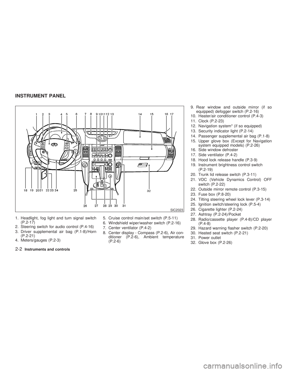
1. Headlight, fog light and turn signal switch
(P.2-17)
2. Steering switch for audio control (P.4-16)
3. Driver supplemental air bag (P.1-8)/Horn
(P.2-21)
4. Meters/gauges (P.2-3) 5. Cruise control main/set switch (P.5-11)
6. Windshield wiper/washer switch (P.2-16)
7. Center ventilator (P.4-2)
8. Center display - Compass (P.2-6), Air con-
ditioner (P.2-6), Ambient temperature
(P.2-6) 9. Rear window and outside mirror (if so
equipped) defogger switch (P.2-16)
10. Heater/air conditioner control (P.4-3)
11. Clock (P.2-23)
12. Navigation system* (if so equipped)
13. Security indicator light (P.2-14)
14. Passenger supplemental air bag (P.1-8)
15. Upper glove box (Except for Navigation
system equipped models) (P.2-26)
16. Side window defroster
17. Side ventilator (P.4-2)
18. Hood lock release handle (P.3-9)
19. Instrument brightness control switch
(P.2-19)
20. Trunk lid release switch (P.3-11)
21. VDC (Vehicle Dynamics Control) OFF
switch (P.2-22)
22. Outside mirror remote control (P.3-15)
23. Fuse box (P.8-20)
24. Tilting steering wheel lock lever (P.3-14)
25. Ignition switch/steering lock (P.5-4)
26. Cigarette lighter (P.2-24)
27. Ashtray (P.2-24)/Pocket
28. Radio/cassette player (P.4-8)/CD player
(P.4-8)
29. Hazard warning flasher switch (P.2-20)
30. Heated seat switch (P.2-21)
31. Power outlet
32. Glove box (P.2-26) SIC2023INSTRUMENT PANEL
2-2 Instruments and controls
Z 02.7.29/V35-D/V5.0
X
Page 60 of 256

The low fuel warning light comes on when
the fuel tank is getting low. Refuel as soon
as it is convenient, preferably before the
gauge reaches E. There will be a small
reserve of fuel in the tank when the fuel
gauge needle reaches E.
The indicates that the fuel filler lid is
located on the passenger's side of the vehicle.
CAUTIONO If the vehicle runs out of fuel, the
malfunction indicator lamp
(MIL) may come on. Refuel as soon as
possible. After a few driving trips, the
lamp should turn off. If the lamp
remains on after a few driving trips,
have the vehicle inspected by an au-
thorized INFINITI retailer.
O For additional information, see the
ªMalfunction indicator lamp (MIL)º
later in this section.
Push COMP switch to turn the display on or off
when the ignition key is in the ON position. The
heading direction will be displayed. N: north
E: east
S: south
W: west
m : vehicle direction
The above example shows the display
changes from ªEastº to ªEast-southeastº.
If the compass unit does not receive any
correct signal for 10 minutes, the compass will
display the bar ª-- -- --º. Have the vehicle
inspected by an authorized INFINITI retailer.
SIC1842BCOMPASS DISPLAY
2-6 Instruments and controls
Z 02.7.29/V35-D/V5.0
X
Page 63 of 256

or Anti-lock brake warning light Low washer fluid warning light High beam indicator light (Blue)
Automatic transmission check warning
light Seat belt warning light Malfunction indicator lamp (MIL)
or Brake warning light Supplemental air bag warning light Slip indicator light
Charge warning light or Automatic transmission posi-
tion indicator light Vehicle dynamics control off indicator
light
Door open warning light Cruise main switch indicator light Turn signal/hazard indicator lights
Engine oil pressure warning light Cruise set switch indicator light
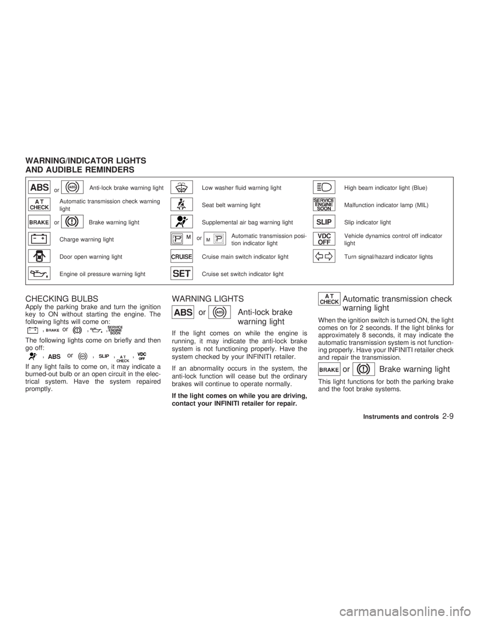
CHECKING BULBS Apply the parking brake and turn the ignition
key to ON without starting the engine. The
following lights will come on:
, or , ,
The following lights come on briefly and then
go off:
, or , , ,
If any light fails to come on, it may indicate a
burned-out bulb or an open circuit in the elec-
trical system. Have the system repaired
promptly. WARNING LIGHTS
or Anti-lock brake
warning lightIf the light comes on while the engine is
running, it may indicate the anti-lock brake
system is not functioning properly. Have the
system checked by your INFINITI retailer.
If an abnormality occurs in the system, the
anti-lock function will cease but the ordinary
brakes will continue to operate normally.
If the light comes on while you are driving,
contact your INFINITI retailer for repair. Automatic transmission check
warning light When the ignition switch is turned ON, the light
comes on for 2 seconds. If the light blinks for
approximately 8 seconds, it may indicate the
automatic transmission system is not function-
ing properly. Have your INFINITI retailer check
and repair the transmission.
or Brake warning light This light functions for both the parking brake
and the foot brake systems.WARNING/INDICATOR LIGHTS
AND AUDIBLE REMINDERS
Instruments and controls
2-9
Z 02.7.29/V35-D/V5.0
X
Page 67 of 256

control off switch is pushed to OFF. This
indicates the vehicle dynamics control system
and traction control system are not operating.
When the vehicle dynamics control off indica-
tor light and slip indicator light come on with
the vehicle dynamics control system turned
on, this light alerts the driver to the fact that the
vehicle dynamics control system's fail-safe
mode is operating, i.e. the vehicle dynamics
control system may not be functioning prop-
erly. Have the system checked by your
INFINITI retailer. If an abnormality occurs in
the system, the vehicle dynamics control sys-
tem function will be canceled but the vehicle is
still driveable. For additional information, see
ªVehicle dynamics control system (VDC)º in
the ª5. Starting and drivingº section of this
manual.
Turn signal/hazard indicator
lightsThe light flashes when the turn signal switch
lever or hazard switch is turned on.
AUDIBLE REMINDERS
Key reminder chime The chime will sound if the driver's side door is
opened while the key is left in the ignition
switch (ignition switch is turned off). Remove the key and take it with you when leaving the
vehicle.
Light reminder chime The chime will sound when the front door is
opened with the headlight switch on unless the
ignition key is in the ON position.
Make sure to turn the light switch off when you
leave the vehicle.
Brake pad wear warning The disc brake pads have audible wear warn-
ings. When a brake pad requires replacement,
it will make a high pitched scraping sound
when the vehicle is in motion whether or not
the brake pedal is depressed. Have the brakes
checked as soon as possible if the warning
sound is heard. Your vehicle has two types of security sys-
tems, as follows:
O Vehicle Security System
O Infiniti Vehicle Immobilizer System
The security condition will be shown by the
security indicator light.
VEHICLE SECURITY SYSTEM The vehicle security system provides visual
and audio alarm signals if parts of the vehicle
are disturbed.SECURITY SYSTEMS
Instruments and controls
2-13
Z 02.7.29/V35-D/V5.0
X
Page 71 of 256

XENON HEADLIGHTS (if so
equipped)
WARNING HIGH VOLTAGE
O When xenon headlights are on, they
produce a high voltage. To prevent an
electric shock, never attempt to
modify or disassemble. Always have
your xenon headlights replaced at an authorized INFINITI retailer.
O Xenon headlights provide consider-
ably more light than conventional
headlights. If they are not correctly
aimed, they might temporarily blind
an oncoming driver or the driver
ahead of you and cause a serious
accident. If headlights are not aimed
correctly, immediately take your ve-
hicle to an authorized INFINITI retailer
and have the headlights adjusted
correctly. When the xenon headlight is initially turned on,
its brightness or color varies slightly. However,
the color and brightness will soon stabilize.
O The life of xenon headlights will be
shortened by frequent on-off operation.
It is generally desirable not to turn off
the headlights for short intervals (for
example, when the vehicle stops at a
traffic signal). Even when the daytime
running lights are active (Canada only),
the xenon headlights do not turn on.
This way the life of the xenon headlights
is not reduced.
O If a xenon headlight bulb is close to
burning out, the brightness will drasti-
cally decrease, the light will start blink-
ing, or the color of the light will become
reddish. If one or more of the above
signs appear, contact an INFINITI re-
tailer.
HEADLIGHT SWITCH
Lighting Turn the switch to the AUTO position:
When the ignition key is in the ON position, the
tail lights, headlights, instrument lights and
other lights turn on automatically, depending
on the brightness of the surroundings. The SIC1834
HEADLIGHT AND TURN SIGNAL
SWITCH
Instruments and controls
2-17
Z 02.7.29/V35-D/V5.0
X
Page 73 of 256

Instrument brightness control The instrument brightness control operates
when the light switch is in the or
position.
Turn the control to adjust the brightness of
instrument panel lights and clock (except
power window switch lights).
When the control is turned upward until it
stops, the light intensity will be at maximum.
When the control is turned downward until it
stops, the light will be turned off. Headlight beam select To select the high beam, push the lever for-
ward. Pull it back to select the low beam.
Flashing signal Pulling the lever toward you will flash the
headlight high beam.
Daytime running light system
(Canada only) The headlights automatically illuminate at a
reduced intensity when the engine is started
with the parking brake released. The daytime
running lights operate with the headlight switch
in the OFF position or in the position.
Turn the headlight switch to the position
for full illumination when driving at night.
If the parking brake is applied before the
engine is started, the daytime running lights do
not illuminate. The daytime running lights illu-
minate once the parking brake is released.
The daytime running lights will remain on until
the ignition switch is turned off. WARNING When the daytime running light system
is active, tail lights on your vehicle are
not on. It is necessary at dusk to turn on
your headlights. Failure to do so could
cause an accident injuring yourself and
others.
TURN SIGNAL SWITCH
Turn signal Move the lever up or down to signal the turning
direction. When the turn is completed, the turn
signals cancel automatically.
Lane change signal To indicate a lane change, move the lever up
or down to the point where lights begin flash-
ing.SIC0922
Instruments and controls
2-19
Z 02.7.29/V35-D/V5.0
X
Page 74 of 256

To turn the fog lights on, turn the headlight
switch to the position, then turn the
switch to the position. To turn them off,
turn the switch to the OFF position.
The headlights must be on for the fog lights to
operate. Push the switch on to warn other drivers when
you must stop or park under emergency con-
ditions. All turn signal lights will flash.
Some state or provincial laws may prohibit
the use of the hazard warning flasher
switch while driving.
WARNING O If stopping for an emergency, be sure
to move the vehicle well off the road. O Do not use the hazard warning flash-
ers while moving on the highway un-
less unusual circumstances force
you to drive so slowly that your ve-
hicle might become a hazard to other
traffic.
O Turn signals do not work when the
hazard warning flasher lights are on.
The flasher can be actuated with the ignition
switch either off or on.SIC1836 SIC1447
FOG LIGHT SWITCH
HAZARD WARNING FLASHER
SWITCH
2-20 Instruments and controls
Z 02.7.29/V35-D/V5.0
X
Page 93 of 256

programmed HomeLink button - releasing
when the device begins to activate.
5. If the indicator light on the HomeLink
blinks rapidly for two seconds and then
turns solid, HomeLink has picked up a
ªrolling codeº garage door opener signal.
You will need to proceed with the next steps
to train the HomeLink to complete the
programming which may require a ladder
and another person for convenience.
6. Press and release the ªsmartº or ªlearnº
program button located on the garage door
opener's motor to activate the ªtraining
modeº. This button is usually located near
the antenna wire that hangs down from the
motor. If the wire originates from under a
light lens, you will need to remove the lens
to access the program button.
NOTE:
Once you have pressed and released the
program button on the garage door open-
er's motor and the ªtraining lightº is lit, you
have 30 seconds in which to perform step
7. Use the help of a second person for
convenience to assist when performing
this step.
7. Quickly within 30 seconds of pressing and
releasing the garage door opener program button, firmly press and release the
HomeLink button you've just pro-
grammed. Press and release the
HomeLink button up to three times to
complete the training.
8. Your HomeLink button should now be
programmed. (To program the remaining
HomeLink buttons for additional door or
gate openers, follow steps 2-8 only.
NOTE:
Do not repeat step one unless you want to
ªclearº all previously programmed
HomeLink buttons).
If you have any questions or are having diffi-
culty programming your HomeLink buttons,
please refer to the HomeLink web site at:
www.homelink.com or call 1-800-662-6200.
PROGRAMMING HomeLink FOR
CANADIAN CUSTOMERS Prior to 1992, D.O.C. regulations required
hand-held transmitters to stop transmitting af-
ter 2 seconds. To program your hand-held
transmitter to HomeLink , continue to press
and hold the HomeLink button (note steps 2
through 4 under ªProgramming HomeLink º)
while you press and re-press (ªcycleº) your
hand-held transmitter every 2 seconds until the indicator light flashes rapidly (indicating
successful programming).
NOTE:
If programming a garage door opener, etc.,
it is advised to unplug the device during
the ªcyclingº process to prevent possible
damage to the garage door opener compo-
nents.
OPERATING THE HomeLink
UNIVERSAL TRANSCEIVER The HomeLink Universal Transceiver (once
programmed) may now be used to activate the
garage door, etc. To operate, simply press the
appropriate programmed HomeLink Univer-
sal Transceiver button. The red indicator light
will illuminate while the signal is being trans-
mitted.
PROGRAMMING TROUBLE
DIAGNOSIS If the HomeLink does not quickly learn the
hand-held transmitter information:
O replace the hand-held transmitter batteries
with new batteries.
O position the hand-held transmitter with its
battery area facing away from the
HomeLink surface. Instruments and controls
2-39
Z 02.7.29/V35-D/V5.0
X
Page 122 of 256

up easily when operating the heater or air
conditioning system. The air conditioning system in your INFINITI
vehicle is charged with a refrigerant designed
with the environment in mind. This refrigerant
will not harm the earth's ozone layer. How-
ever, special charging equipment and lubricant
are required when servicing your NISSAN air
conditioner. Using improper refrigerants or lu-
bricants will cause severe damage to your air
conditioning system. See ªCapacities and rec-
ommended fuel/lubricantsº in the ª10. Techni-
cal and consumer informationº section for air
conditioning system refrigerant and lubricant
recommendations.
Your INFINITI retailer will be able to service
your environmentally friendly air conditioning
system.
WARNING The air conditioner system contains re-
frigerant under high pressure. To avoid
personal injury, any air conditioner ser-
vice should be done only by an experi-
enced technician with proper equip-
ment. Turn the ignition key to ACC or ON and press
the POWER, FM or AM button to turn on the
radio. If you listen to the radio with the engine
not running, the key should be turned to the
ACC position.
Radio reception is affected by station signal
strength, distance from radio transmitter, build-
ings, bridges, mountains and other external
influences. Intermittent changes in reception
quality normally are caused by these external
influences.
Using a cellular phone in or near the ve-
hicle may influence radio reception quality.
Radio reception Your radio system is equipped with state-of-
the-art electronic circuits to enhance radio
reception. These circuits are designed to ex-
tend reception range, and to enhance the
quality of that reception.
However there are some general characteris-
tics of FM, AM and satellite radio signals that
can affect radio reception quality in a moving
vehicle, even when the finest equipment is
used. These characteristics are completely
normal in a given reception area, and do not
indicate any malfunction in your radio system.
Remember that a moving vehicle is not the
ideal place to listen to a radio. Because of theSERVICING AIR CONDITIONER AUDIO SYSTEM
4-6 Heater, air conditioner and audio systems
Z 02.7.29/V35-D/V5.0
X