display INFINITI G35 2006 Owners Manual
[x] Cancel search | Manufacturer: INFINITI, Model Year: 2006, Model line: G35, Model: INFINITI G35 2006Pages: 344, PDF Size: 6.81 MB
Page 5 of 344

Table of
Contents Illustrated table of contents 0
Safety Ð Seats, seat belts and supplemental restraint system 1
Instruments and controls 2
Pre-driving checks and adjustments 3
Display screen, heater, air conditioner and audio systems 4
Starting and driving 5
In case of emergency 6
Appearance and care 7
Maintenance and do-it-yourself 8
Technical and consumer information 9
Index 10
w 06.1.4/V35-D/V5.0
X
Page 15 of 344

1. Headlight, fog light and turn signal
switch (P.2-21)
2. Security indicator light (P.2-19)
3. Steering wheel switch for audio control
(P.4-28) or steering wheel switch for
Bluetooth Hands-Free Phone System
(if so equipped) (P.4-30) 4. Driver's supplemental front air bag
(P.1-36)/Horn (P.2-26)
5. Meters/gauges (P.2-3)
6. Cruise control main/set switch (P.5-20)
7. Windshield wiper/washer switch
(P.2-19)
8. Center ventilator (P.4-9) 9. Center display - Compass, Air condi-
tioner, Ambient temperature, Front
passenger air bag status light (P.1-44)
10. Rear window and outside mirror de-
fogger switch (P.2-20)
11. Heater/air conditioner control (P.4-10)
12. Clock (P.2-29)
13. Navigation system* (if so equipped)
(P.4-2)
14. Passenger's supplemental front air
bag (P.1-36)
15. Upper glove box (except for Naviga-
tion system equipped models)
(P.2-35)
16. Side ventilator (P.4-9)
17. Hood lock release handle (P.3-24)
18. Trunk lid release switch (P.3-25)
19. Vehicle Dynamic Control (VDC) off
switch (P.2-28)
20. Instrument brightness control
(P.2-24)
21. Outside mirror remote control switch
(P.3-33)
22. Fuse box (P.8-27)
23. Electric steering column control (if so
equipped) (P.3-31)
24. Manual steering column control
(P.3-30)
25. Ignition switch/steering lock (P.5-6)
26. SNOW mode switch (if so equipped)
(P.2-27)
27. Audio system (P.4-14)
28. Ashtray/Cigarette lighter (P.2-30)
29. Heated seat switch (P.2-26) SSI0159INSTRUMENT PANEL
Illustrated table of contents
0-9
w 06.1.4/V35-D/V5.0
X
Page 63 of 344

all instructions in this manual concerning
the use of seats, seat belts and child re-
straints can increase the risk or severity of
injury in an accident.
Status light:
The front passenger air bag status light
is located in the center display. The
light operates as follows:
O Unoccupied passenger seat: The is
OFF and the front passenger air bag is
OFF and will not inflate in a crash.
O Passenger seat occupied by a small
adult, child or child restraint as out-
lined in this section: The illumi-
nates to indicate that the front pas-
senger air bag is OFF and will not in-
flate in a crash.
O Occupied passenger seat and the pas-
senger meets the conditions outlined
in this section: The light is OFF to
indicate that the front passenger air
bag is operational.
Front passenger air bag:
The front passenger air bag is designed to
automatically turn OFF when the vehicle is operated under some conditions as de-
scribed below in accordance with U.S.
regulations. If the front passenger air bag
is OFF, it will not inflate in a crash. The
driver air bag and other air bags in your
vehicle are not part of this system.
The purpose of the regulation is to help
reduce the risk of injury or death from an
inflating air bag to certain front passenger
seat occupants, such as children, by re-
quiring the air bag to be automatically
turned OFF. Certain sensors are used to
meet the requirements.
One sensor used is the occupant classifi-
cation sensor (pressure sensor). It is in
the bottom of the front passenger seat
cushion and is designed to detect an oc-
cupant and objects on the seat by weight.
It works together with seat belt sensors
described later. For example, if a child is
in the front passenger seat, the advanced
air bag system is designed to turn the
passenger air bag OFF in accordance with
the regulations. Also, if a child restraint of
the type specified in the regulations is on
the seat, its weight and the child's weight
can be detected and cause the air bag to
turn OFF. Occupant classification sensor
operation can vary depending on the front
passenger seat belt sensors. The front passenger seat belt sensors are
designed to detect if the seat belt is
buckled and the amount of tension on the
seat belt, such as when it is in the auto-
matic locking mode (child restraint mode).
Based on the weight on the seat detected
by the occupant classification sensor and
the belt tension detected on the seat belt,
the INFINITI advanced air bag system de-
termines whether the front passenger air
bag should be automatically turned OFF
as required by the regulations.
Front passenger seat adult occupants who
are properly seated and using the seat
belt as outlined in this manual should not
cause the passenger air bag to be auto-
matically turned OFF. For small adults it
may be turned OFF, however, if the occu-
pant takes his/her weight off the seat
cushion (for example, by not sitting up-
right, by sitting on an edge of the seat, or
by otherwise being out of position), this
could cause the sensor to turn the air bag
OFF. In addition, if the occupant improp-
erly uses the seat belt in the automatic
locking mode (child restraint mode), this
could cause the air bag to be turned OFF.
Always be sure to be seated and wearing
the seat belt properly for the most effec-
tive protection by the seat belt and
supplemental air bag.
Safety Ð Seats, seat belts and supplemental restraint system
1-45
w 06.1.4/V35-D/V5.0
X
Page 69 of 344

q 1
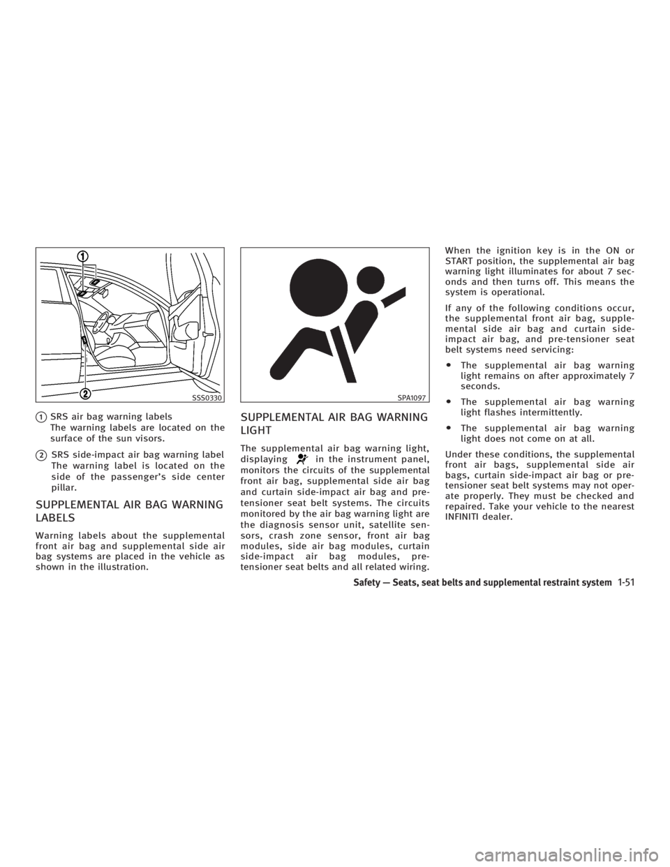
SRS air bag warning labels
The warning labels are located on the
surface of the sun visors.
q 2
SRS side-impact air bag warning label
The warning label is located on the
side of the passenger's side center
pillar.
SUPPLEMENTAL AIR BAG WARNING
LABELS Warning labels about the supplemental
front air bag and supplemental side air
bag systems are placed in the vehicle as
shown in the illustration. SUPPLEMENTAL AIR BAG WARNING
LIGHT The supplemental air bag warning light,
displaying in the instrument panel,
monitors the circuits of the supplemental
front air bag, supplemental side air bag
and curtain side-impact air bag and pre-
tensioner seat belt systems. The circuits
monitored by the air bag warning light are
the diagnosis sensor unit, satellite sen-
sors, crash zone sensor, front air bag
modules, side air bag modules, curtain
side-impact air bag modules, pre-
tensioner seat belts and all related wiring. When the ignition key is in the ON or
START position, the supplemental air bag
warning light illuminates for about 7 sec-
onds and then turns off. This means the
system is operational.
If any of the following conditions occur,
the supplemental front air bag, supple-
mental side air bag and curtain side-
impact air bag, and pre-tensioner seat
belt systems need servicing:
O The supplemental air bag warning
light remains on after approximately 7
seconds.
O The supplemental air bag warning
light flashes intermittently.
O The supplemental air bag warning
light does not come on at all.
Under these conditions, the supplemental
front air bags, supplemental side air
bags, curtain side-impact air bag or pre-
tensioner seat belt systems may not oper-
ate properly. They must be checked and
repaired. Take your vehicle to the nearest
INFINITI dealer.SSS0330 SPA1097
Safety Ð Seats, seat belts and supplemental restraint system
1-51
w 06.1.4/V35-D/V5.0
X
Page 72 of 344

2 Instruments and controls Instrument panel .............................................. 2-2
Meters and gauges ........................................... 2-3
Speedometer and odometer ........................ 2-3
Tachometer ................................................. 2-4
Engine coolant temperature gauge .............. 2-4
Fuel gauge .................................................. 2-5
Compass display .............................................. 2-6
Warning/indicator lights and audible
reminders ......................................................... 2-9
Checking bulbs ........................................... 2-9
Warning lights............................................. 2-9
Indicator lights .......................................... 2-14
Audible reminders ..................................... 2-16
Security systems ............................................. 2-17
Vehicle security system.............................. 2-17
INFINITI Vehicle Immobilizer System .......... 2-18
Windshield wiper and washer switch .............. 2-19
Rear window and outside mirror defroster
switch ............................................................ 2-20
Headlight and turn signal switch..................... 2-21
Xenon headlights ....................................... 2-21
Headlight switch ........................................ 2-21
Turn signal switch ..................................... 2-24
Fog light switch ......................................... 2-25 Hazard warning flasher switch ........................ 2-25
Horn ............................................................... 2-26
Heated seats .................................................. 2-26
SNOW mode switch (if so equipped) ............... 2-27
Vehicle Dynamic Control (VDC) off switch ....... 2-28
Clock .............................................................. 2-29
Adjusting the time..................................... 2-29
Power outlet ................................................... 2-29
Cigarette lighter and ashtray .......................... 2-30
Front ......................................................... 2-30
Rear .......................................................... 2-30
Storage ........................................................... 2-31
Door pocket .............................................. 2-31
Instrument pocket (except for navigation
system equipped models) .......................... 2-31
Sunglasses holder .................................... 2-32
Cup holder ................................................ 2-32
Glove box .................................................. 2-35
Upper glove box (except for navigation
system equipped models).......................... 2-35
Console box .............................................. 2-36
Rear armrest pocket (Sedan) ..................... 2-37
Card holder (driver's side) ......................... 2-38
Coat hook (Coupe) .................................... 2-38
w 06.1.5/V35-D/V5.0
X
Page 74 of 344

1. Headlight, fog light and turn signal
switch
2. Security indicator light
3. Steering wheel switch for audio control
or steering wheel switch for Bluetooth Hands-Free Phone System
(if so equipped)
4. Driver supplemental air bag/Horn
5. Meters/gauges
6. Cruise control main/set switch
7. Windshield wiper/washer switch 8. Center ventilator
9. Center display - Compass, Air condi-
tioner, Ambient temperature, Front
passenger air bag status light
10. Rear window and outside mirror de-
fogger switch
11. Heater/air conditioner control
12. Clock
13. Navigation system* (if so equipped)
14. Passenger supplemental air bag
15. Upper glove box (except for Naviga-
tion system equipped models)
16. Side ventilator
17. Hood lock release handle
18. Trunk lid release switch
19. Vehicle Dynamic Control (VDC) off
switch
20. Instrument brightness control
21. Outside mirror remote control switch
22. Fuse box
23. Electric steering column control (if so
equipped)
24. Manual steering column control
25. Ignition switch/steering lock
26. Snow mode switch (if so equipped)
27. Audio system
28. Ashtray/Cigarette lighter
29. Heated seat switch
30. Hazard warning flasher switch
31. Glove box
*: Refer to the separate Navigation System
Owner's Manual. SSI0159INSTRUMENT PANEL
2-2 Instruments and controls
w 06.1.4/V35-D/V5.0
X
Page 75 of 344

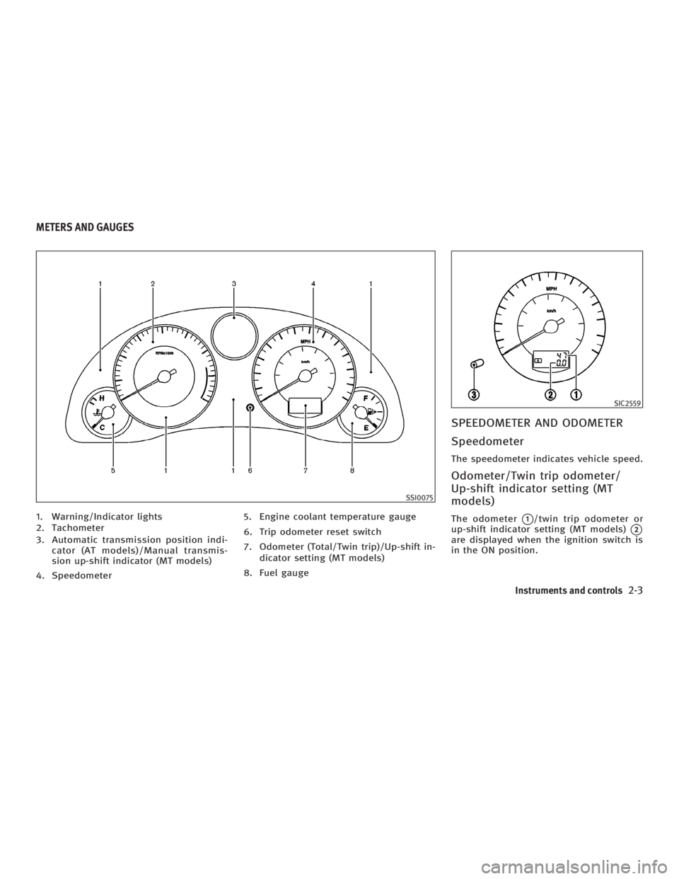
1. Warning/Indicator lights
2. Tachometer
3. Automatic transmission position indi-
cator (AT models)/Manual transmis-
sion up-shift indicator (MT models)
4. Speedometer 5. Engine coolant temperature gauge
6. Trip odometer reset switch
7. Odometer (Total/Twin trip)/Up-shift in-
dicator setting (MT models)
8. Fuel gauge SPEEDOMETER AND ODOMETER
Speedometer The speedometer indicates vehicle speed.
Odometer/Twin trip odometer/
Up-shift indicator setting (MT
models) The odometer
q 1
/twin trip odometer or
up-shift indicator setting (MT models)
q 2
are displayed when the ignition switch is
in the ON position. SSI0075 SIC2559
METERS AND GAUGES
Instruments and controls
2-3
w 06.1.4/V35-D/V5.0
X
Page 76 of 344

The odometer records the total distance
the vehicle has been driven.
The twin trip odometer records the dis-
tance of individual trips.
Changing the display:
Pushing the trip odometer reset switch
q 3
changes the display as follows.
AT models:
TRIP A ! TRIP B ! TRIP A
MT models:
TRIP A ! TRIP B ! Up-shift indicator set-
ting mode ! TRIP A
See ªDriving the vehicleº in the ª5. Start-
ing and drivingº section for the use of the
up-shift indicator.
Resetting the trip odometer:
Pushing the trip odometer reset switch for
more than 1 second resets the trip odom-
eter to zero.
TACHOMETER The tachometer indicates engine speed in
revolutions per minute (rpm). Do not rev
the engine into the red zone
q A
.
CAUTION When engine speed approaches the red
zone, shift to a higher gear. Operating the
engine in the red zone may cause serious en-
gine damage. ENGINE COOLANT TEMPERATURE
GAUGE The gauge indicates the engine coolant
temperature.
The engine coolant temperature is within
the normal range
q A
when the gauge
needle points within the zone shown in
the illustration.
The engine coolant temperature will vary
with the outside air temperature and driv-
ing conditions. SIC2560 SIC2561
2-4 Instruments and controls
w 06.1.4/V35-D/V5.0
X
Page 78 of 344

The compass is located in the center dis-
play.
Push COMP switch
q A
to turn the display
on or off when the ignition switch is in
the ON position. The heading direction
will be displayed. N: north
E: east
S: south
W: west
C : vehicle direction
The above example shows the display
changes from ªEastº to ªEast-southeastº.
If the compass unit does not receive any
correct signal for 10 minutes, the com-
pass will display the bar ª-- -- --º. Have
the vehicle checked by an INFINITI dealer.
SIC2563COMPASS DISPLAY
2-6 Instruments and controls
w 06.1.4/V35-D/V5.0
X
Page 79 of 344

Zone variation change procedure The difference between magnetic north
and geographical north is known as vari-
ance. In some areas, this difference can
sometimes be great enough to cause
false compass readings. Follow these in-
structions to set the variance for your par-
ticular location if this happens:
1. Establish your location on the zone
map
q A
. Record your zone number.
2. Turn the ignition switch to the ON po-
sition while pushing the COMP switch.
3. Continue to push the COMP switch for
more than 5 seconds until the current
zone entry number is displayed on the
compass display.
If any operations are not carried out
for more than 5 seconds, the display
shows direction as normal.
4. Push the COMP switch repeatedly until
the new zone entry number is dis-
played.
Once the desired zone number is dis-
played, stop pushing the COMP switch
and the display will show compass direc-
tion within a few seconds. SIC2243A
Instruments and controls
2-7
w 06.1.4/V35-D/V5.0
X