manual transmission INFINITI G35 2006 Owners Manual
[x] Cancel search | Manufacturer: INFINITI, Model Year: 2006, Model line: G35, Model: INFINITI G35 2006Pages: 344, PDF Size: 6.81 MB
Page 13 of 344
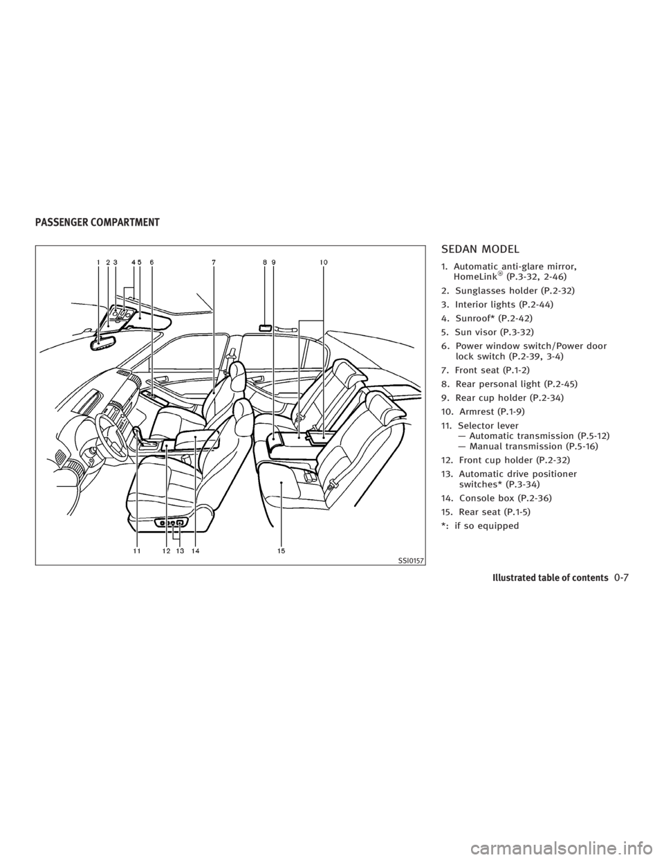
SEDAN MODEL 1. Automatic anti-glare mirror,
HomeLink (P.3-32, 2-46)
2. Sunglasses holder (P.2-32)
3. Interior lights (P.2-44)
4. Sunroof* (P.2-42)
5. Sun visor (P.3-32)
6. Power window switch/Power door
lock switch (P.2-39, 3-4)
7. Front seat (P.1-2)
8. Rear personal light (P.2-45)
9. Rear cup holder (P.2-34)
10. Armrest (P.1-9)
11. Selector lever
Ð Automatic transmission (P.5-12)
Ð Manual transmission (P.5-16)
12. Front cup holder (P.2-32)
13. Automatic drive positioner
switches* (P.3-34)
14. Console box (P.2-36)
15. Rear seat (P.1-5)
*: if so equipped SSI0157PASSENGER COMPARTMENT
Illustrated table of contents
0-7
w 06.1.4/V35-D/V5.0
X
Page 14 of 344

COUPE MODEL 1. Automatic anti-glare mirror, HomeLink
(P.3-32, 2-46)
2. Sunglasses holder (P.2-32)
3. Interior lights (P.2-44)
4. Sunroof* (P.2-42)
5. Sun visor (P.3-32)
6. Power window switch/Power door lock
switch (P.2-39, 3-4)
7. Front seat (P.1-2)
8. Coat hook (P.2-38)
9. Selector lever or Shift lever
Ð Automatic transmission (P.5-12)
Ð Manual transmission (P.5-16)
10. Parking brake (P.5-19)
11. Automatic drive positioner switches*
(P.3-34)
12. Front cup holder (P.2-32)
13. Console box (P.2-36)
14. Walk-in mechanism* (P.1-4)
15. Shoulder belt guide (P.1-17)
16. Rear cup holder (P.2-34)
17. Rear seat (P.1-5)
*: if so equipped SSI0158
0-8 Illustrated table of contents
w 06.1.4/V35-D/V5.0
X
Page 17 of 344
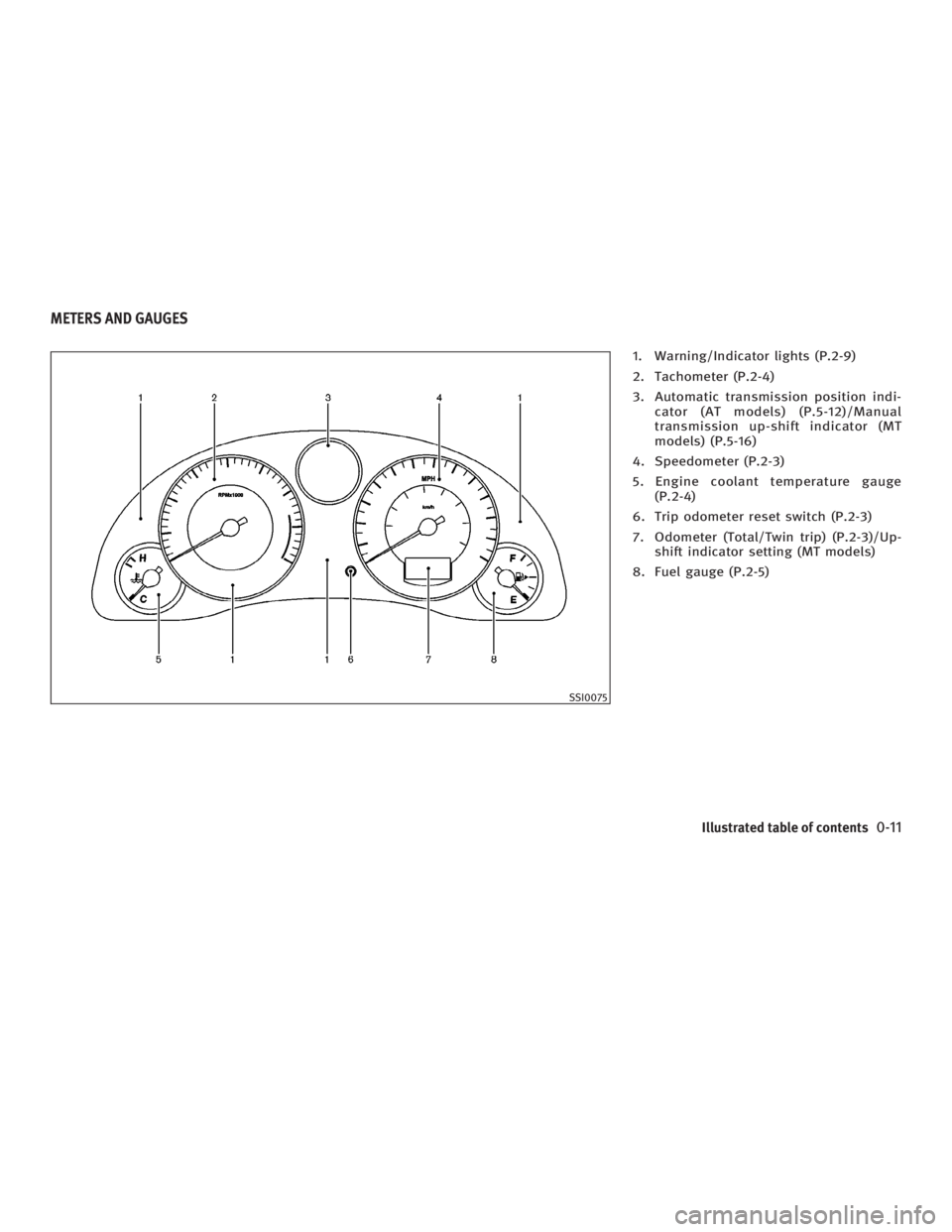
1. Warning/Indicator lights (P.2-9)
2. Tachometer (P.2-4)
3. Automatic transmission position indi-
cator (AT models) (P.5-12)/Manual
transmission up-shift indicator (MT
models) (P.5-16)
4. Speedometer (P.2-3)
5. Engine coolant temperature gauge
(P.2-4)
6. Trip odometer reset switch (P.2-3)
7. Odometer (Total/Twin trip) (P.2-3)/Up-
shift indicator setting (MT models)
8. Fuel gauge (P.2-5)
SSI0075METERS AND GAUGES
Illustrated table of contents
0-11
w 06.1.4/V35-D/V5.0
X
Page 23 of 344
turning the front seat to its original posi-
tion.
O When returning the seat to its original
position, confirm the seat and seatback
are locked properly.
O Be careful not to pinch your hand or foot
or bump your head when operating the
walk-in seat. The seatback will fold down
rapidly.
O Do not place any objects near the seat-
back of the front seats. They may be
pinched and damaged.
O Remove the seat belt from the seat belt
guide when operating the walk-in
mechanism to prevent the belt from
being stretched along with the seat
movement.
The automatic forwarding and reversing
will not work or stop under the following
conditions:
O When the vehicle speed is above 4
MPH (7 km/h).
O When the seat belt is fastened. O When the selector lever is not in the P
(Park) position (Automatic transmis-
sion model's driver's seat) or the
parking brake is not applied (Manual
transmission model's driver's seat).
O When the door is closed.
O When the seat is raised or when the
seatback switch, recline switch or
slide switch is operated during auto-
matic operation.
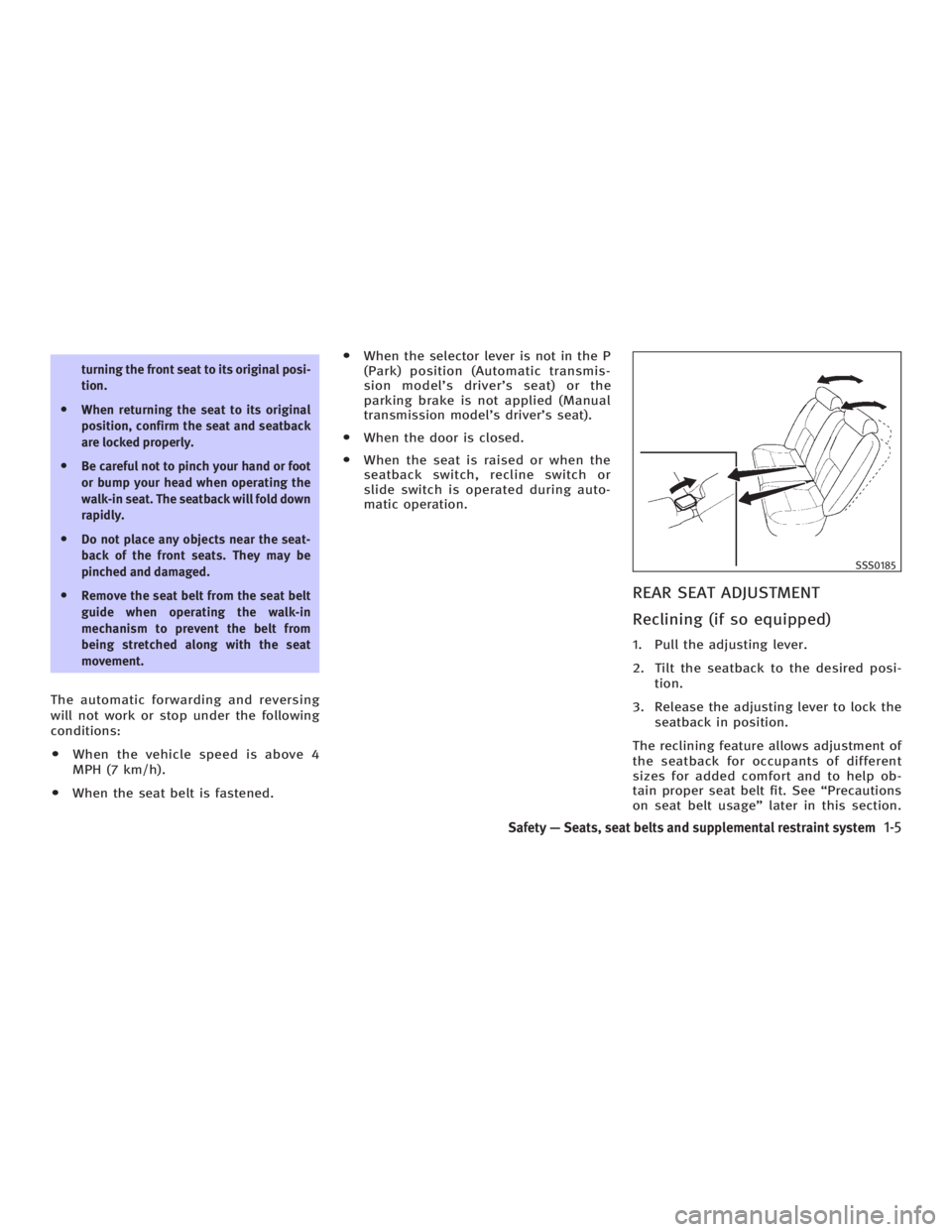
REAR SEAT ADJUSTMENT
Reclining (if so equipped) 1. Pull the adjusting lever.
2. Tilt the seatback to the desired posi-
tion.
3. Release the adjusting lever to lock the
seatback in position.
The reclining feature allows adjustment of
the seatback for occupants of different
sizes for added comfort and to help ob-
tain proper seat belt fit. See ªPrecautions
on seat belt usageº later in this section. SSS0185
Safety Ð Seats, seat belts and supplemental restraint system
1-5
w 06.1.4/V35-D/V5.0
X
Page 75 of 344
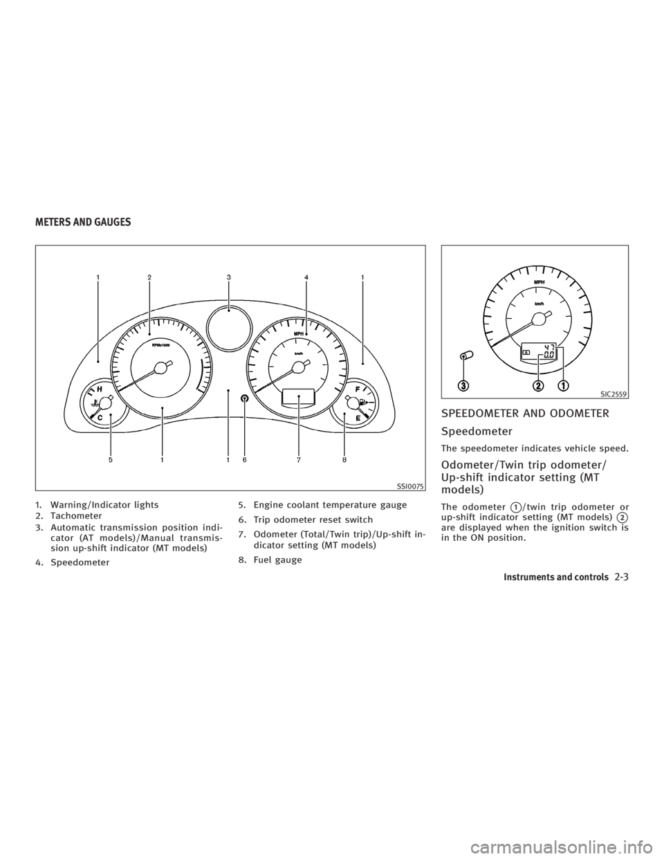
1. Warning/Indicator lights
2. Tachometer
3. Automatic transmission position indi-
cator (AT models)/Manual transmis-
sion up-shift indicator (MT models)
4. Speedometer 5. Engine coolant temperature gauge
6. Trip odometer reset switch
7. Odometer (Total/Twin trip)/Up-shift in-
dicator setting (MT models)
8. Fuel gauge SPEEDOMETER AND ODOMETER
Speedometer The speedometer indicates vehicle speed.
Odometer/Twin trip odometer/
Up-shift indicator setting (MT
models) The odometer
q 1
/twin trip odometer or
up-shift indicator setting (MT models)
q 2
are displayed when the ignition switch is
in the ON position. SSI0075 SIC2559
METERS AND GAUGES
Instruments and controls
2-3
w 06.1.4/V35-D/V5.0
X
Page 101 of 344

If the power supply is disconnected, the
clock will not indicate the correct time. Re-
adjust the time.
ADJUSTING THE TIME To move the time forward, push the
button
q 1
.
To move the time backward, push the
button
q 2
.
Push and hold each adjusting switch to
move the time forward or backward con-
tinuously. The power outlet is for powering electrical
accessories such as cellular telephones.
CAUTION O The outlet and plug may be hot during or
immediately after use.
O This power outlet is not designed for use
with a cigarette lighter unit.
O Do not use with accessories that exceed a
12 volt, 120W (10A) power draw. Do not
use double adapters or more than one
electrical accessory. O Use power outlets with the engine running
to avoid discharging the vehicle battery.
O Avoid using power outlets when the air
conditioner, headlights or rear window de-
froster is on.
O Before inserting or disconnecting a plug,
be sure the electrical accessory being used
is turned OFF.
O Push the plug in as far as it will go. If good
contact is not made, the plug may overheat
or the internal temperature fuse may open.
O When not in use, be sure to close the cap.
Do not allow water to contact the outlet.SIC2568 SIC1840B
Automatic transmission model SIC2673
Manual transmission modelsCLOCK POWER OUTLET
Instruments and controls
2-29
w 06.1.5/V35-D/V5.0
X
Page 105 of 344
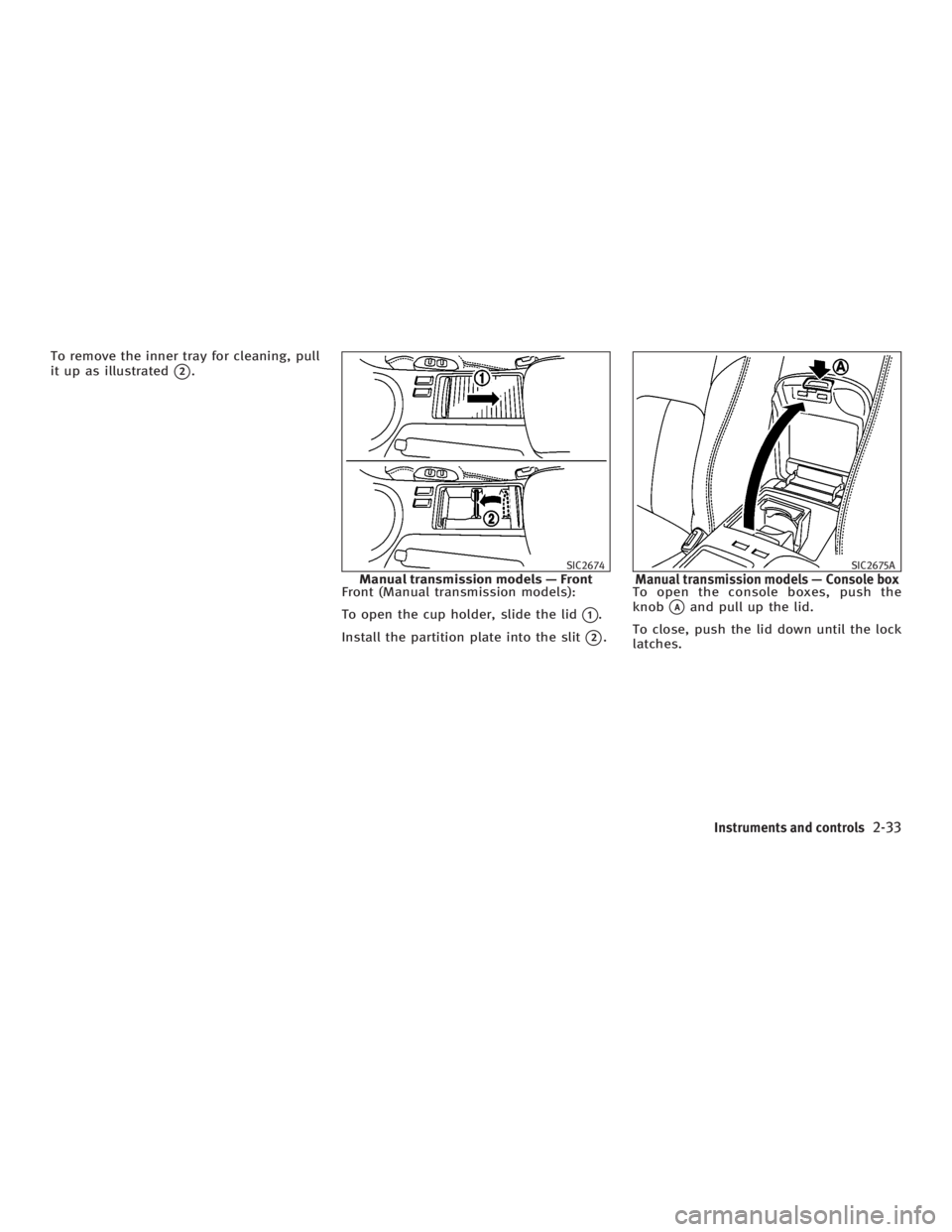
To remove the inner tray for cleaning, pull
it up as illustrated
q 2
.
Front (Manual transmission models):
To open the cup holder, slide the lid
q 1
.
Install the partition plate into the slit
q 2
. To open the console boxes, push the
knob
q A
and pull up the lid.
To close, push the lid down until the lock
latches. SIC2674
Manual transmission models Ð Front SIC2675A
Manual transmission models Ð Console box
Instruments and controls
2-33
w 06.1.4/V35-D/V5.0
X
Page 108 of 344
WARNINGKeep upper glove box lid closed while
driving to help prevent injury in an accident
or a sudden stop.
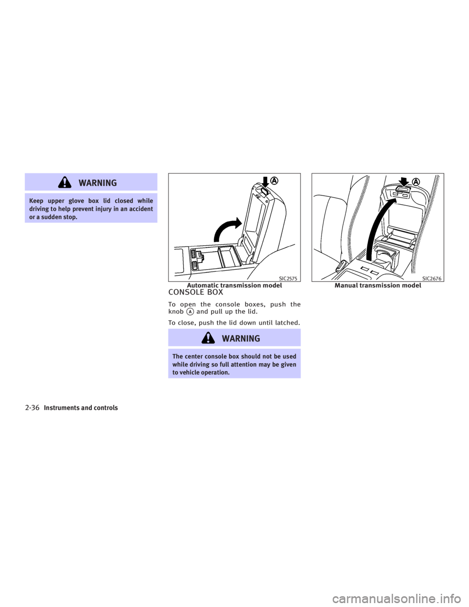
CONSOLE BOX To open the console boxes, push the
knob
q A
and pull up the lid.
To close, push the lid down until latched.
WARNING The center console box should not be used
while driving so full attention may be given
to vehicle operation. SIC2575
Automatic transmission model SIC2676
Manual transmission model
2-36 Instruments and controls
w 06.1.4/V35-D/V5.0
X
Page 109 of 344
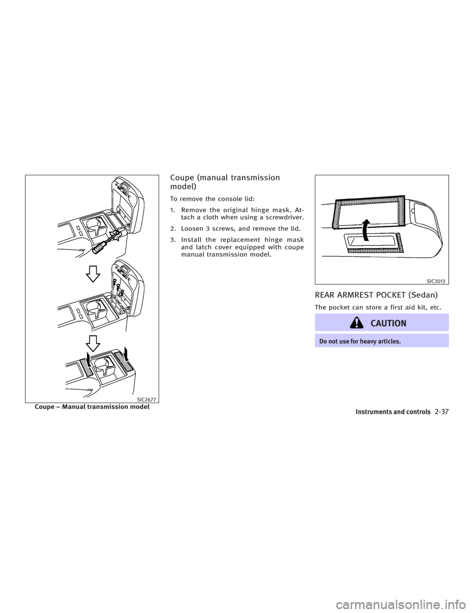
Coupe (manual transmission
model) To remove the console lid:
1. Remove the original hinge mask. At-
tach a cloth when using a screwdriver.
2. Loosen 3 screws, and remove the lid.
3. Install the replacement hinge mask
and latch cover equipped with coupe
manual transmission model.
REAR ARMREST POCKET (Sedan) The pocket can store a first aid kit, etc.
CAUTION Do not use for heavy articles.
SIC2677
Coupe þ Manual transmission model SIC3013
Instruments and controls
2-37
w 06.1.4/V35-D/V5.0
X
Page 156 of 344
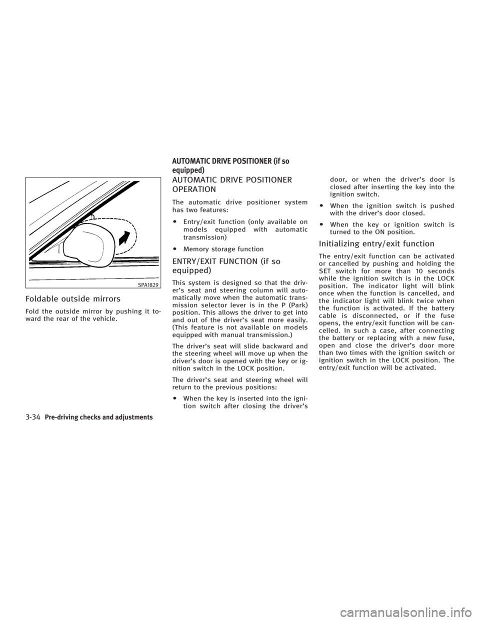
Foldable outside mirrors Fold the outside mirror by pushing it to-
ward the rear of the vehicle. AUTOMATIC DRIVE POSITIONER
OPERATION The automatic drive positioner system
has two features:
O Entry/exit function (only available on
models equipped with automatic
transmission)
O Memory storage function
ENTRY/EXIT FUNCTION (if so
equipped) This system is designed so that the driv-
er's seat and steering column will auto-
matically move when the automatic trans-
mission selector lever is in the P (Park)
position. This allows the driver to get into
and out of the driver's seat more easily.
(This feature is not available on models
equipped with manual transmission.)
The driver's seat will slide backward and
the steering wheel will move up when the
driver's door is opened with the key or ig-
nition switch in the LOCK position.
The driver's seat and steering wheel will
return to the previous positions:
O When the key is inserted into the igni-
tion switch after closing the driver's door, or when the driver's door is
closed after inserting the key into the
ignition switch.
O When the ignition switch is pushed
with the driver's door closed.
O When the key or ignition switch is
turned to the ON position.
Initializing entry/exit function The entry/exit function can be activated
or cancelled by pushing and holding the
SET switch for more than 10 seconds
while the ignition switch is in the LOCK
position. The indicator light will blink
once when the function is cancelled, and
the indicator light will blink twice when
the function is activated. If the battery
cable is disconnected, or if the fuse
opens, the entry/exit function will be can-
celled. In such a case, after connecting
the battery or replacing with a new fuse,
open and close the driver's door more
than two times with the ignition switch or
ignition switch in the LOCK position. The
entry/exit function will be activated.SPA1829
AUTOMATIC DRIVE POSITIONER (if so
equipped)
3-34 Pre-driving checks and adjustments
w 06.1.4/V35-D/V5.0
X