engine INFINITI M 2010 Owner's Guide
[x] Cancel search | Manufacturer: INFINITI, Model Year: 2010, Model line: M, Model: INFINITI M 2010Pages: 445, PDF Size: 6.15 MB
Page 114 of 445

Push the LDW switch again to turn the LDW
system on. The LDW automatic setting mode
can be changed to the manual setting mode. To
change the mode, push and hold the LDW
switch for more than 4 seconds when the LDW
ON indicator is off. In the manual setting mode,
push the LDW switch on and off to turn the LDW
system on and off.
See ªLANE DEPARTURE WARNING (LDW)
SYSTEM/LANE DEPARTURE PREVENTION (LDP)
SYSTEMº in the ª5. Starting and drivingº sec-
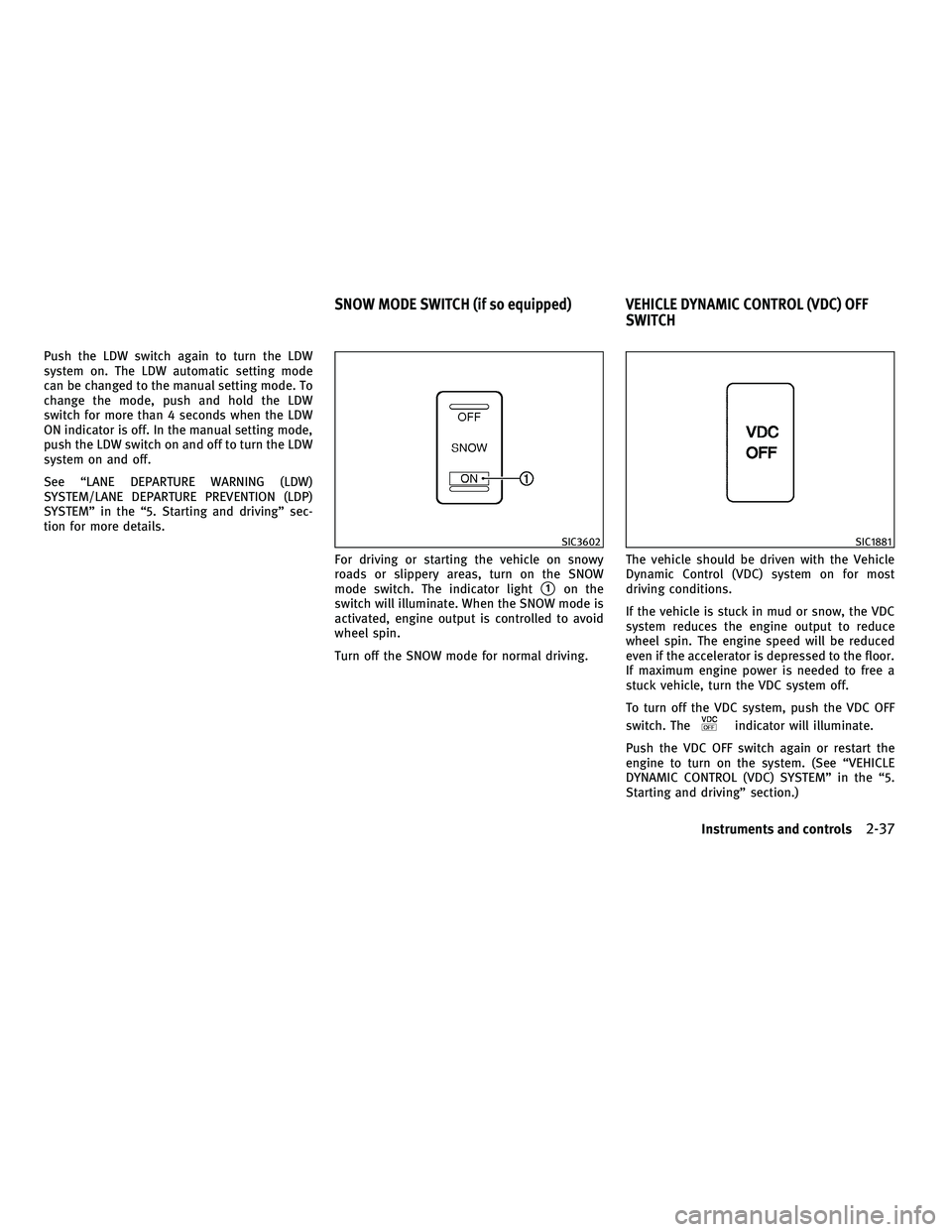
tion for more details.For driving or starting the vehicle on snowy
roads or slippery areas, turn on the SNOW
mode switch. The indicator light
s1on the
switch will illuminate. When the SNOW mode is
activated, engine output is controlled to avoid
wheel spin.
Turn off the SNOW mode for normal driving. The vehicle should be driven with the Vehicle
Dynamic Control (VDC) system on for most
driving conditions.
If the vehicle is stuck in mud or snow, the VDC
system reduces the engine output to reduce
wheel spin. The engine speed will be reduced
even if the accelerator is depressed to the floor.
If maximum engine power is needed to free a
stuck vehicle, turn the VDC system off.
To turn off the VDC system, push the VDC OFF
switch. The
indicator will illuminate.
Push the VDC OFF switch again or restart the
engine to turn on the system. (See ªVEHICLE
DYNAMIC CONTROL (VDC) SYSTEMº in the ª5.
Starting and drivingº section.)
SIC3602SIC1881
SNOW MODE SWITCH (if so equipped) VEHICLE DYNAMIC CONTROL (VDC) OFF SWITCH
Instruments and controls2-37
wÐ
Ð
05/14/09Ðpattie
X
Page 115 of 445

If the power supply is disconnected, the clock
will not indicate the correct time. Readjust the
time.
ADJUSTING THE TIME
1. To set the clock forward, push the button
s1.
2. To set the clock backward, push the but- ton
s2.
3. To move forward or backward faster, push and hold the button more than 5 seconds.
For details about display clock adjustment (if so
equipped), see ªHOW TO USE SETTING BUTTONº
in the ª4. Monitor, climate, audio, phone and
voice recognition systemsº section. The power outlets are located on the back side
and inside (if equipped) of the center console
for powering electrical accessories such as a
cellular telephone.
CAUTION
c
The outlet and plug may be hot during or
immediately after use.
c Do not use with accessories that exceed a 12
volt, 120W (10A) power draw. Do not use
double adapters or more than one electrical
accessory.
c Use power outlet with the engine running to
avoid discharging the vehicle battery.
c Avoid using power outlet when the air condi-
tioner, headlights or rear window defroster
is on.
c This power outlet is not designed for use
with a cigarette lighter unit.
c Push the plug in as far as it will go. If good
contact is not made, the plug may overheat
or the internal temperature fuse may open.
c Before inserting or disconnecting a plug, be
sure the electrical accessory being used is
turned OFF.
c When not in use, be sure to close the cap. Do
not allow water to contact the outlet.
SIC2772SIC2773
Only for model without DVD player
SIC2774
CLOCK POWER OUTLETS
2-38Instruments and controls
wÐ
Ð
05/14/09Ðpattie
X
Page 125 of 445

The rear sunshade operates when the ignition
switch is in the ON position.
The rear sunshade switches are located on the
center console and inside the rear armrest.
To raise the screen, push the UP side of the
switch
s1.
To lower the screen, push the DOWN side of the
switch
s2. The switch need not be held.
CAUTION
c Do not place objects (such as newspapers,
handkerchiefs, etc.) on the screen inlet port.
Doing so may entangle these objects in the
screen when it is extending or retracting,
causing improper operation or damage to
the screen.
c Do not push the sunshade arm with your
hands, etc., as this may deform it. Improper
operation or damage to the screen may
result.
c Do not put any object into the screen inlet
port as this may result in improper operation
or damage the screen.
c Do not hang any object on the arm rail as this
may result in improper operation or damage
the screen.
c Do not forcefully pull the screen. Doing so
may elongate the screen. Improper opera-
tion or damage to the screen may result.
CAUTION
Do not use for extended periods of time with
the engine stopped. This could result in a dis-
charged battery.
SIC2787
INTERIOR LIGHTS
2-48Instruments and controls
wÐ
Ð
05/14/09Ðpattie
X
Page 128 of 445

The light illuminates when the trunk lid is
opened. When the trunk lid is closed, the light
will turn off.
The light will turn off after 30 minutes when the
light remains illuminated to prevent the battery
from becoming discharged.HomeLinkT
Universal Transceiver provides a
convenient way to consolidate the functions of
up to three individual hand-held transmitters
into one built-in device.
HomeLinkT Universal Transceiver:
c Will operate most Radio Frequency (RF) de-
vices such as garage doors, gates, home and
office lighting, entry door locks and security
systems.
c Is powered by your vehicle's battery. No
separate batteries are required. If the vehi-
cle's battery is discharged or is discon-
nected, HomeLink Twill retain all program-
ming.
Once HomeLinkT Universal Transceiver is pro-
grammed, retain the original transmitter for fu-
ture programming procedures (Example: new ve-
hicle purchases). Upon sale of the vehicle, the
programmed HomeLinkT Universal Transceiver
buttons should be erased for security purposes.
For additional information, see ªPROGRAMMING
HomeLinkTº later in this section.WARNING
c Do not use HomeLinkT Universal Transceiver
with any garage door opener that lacks
safety stop and reverse features as required
by federal safety standards. (These stan-
dards became effective for opener models
manufactured after April 1, 1982.) A garage
door opener which cannot detect an object in
the path of a closing garage door and then
automatically stop and reverse, does not
meet current federal safety standards. Using
a garage door opener without these features
increases the risk of serious injury or death.
c During programming procedure, your garage
door or security gate may open or close.
Make sure that people and objects are clear
of the garage door, gate, etc. that you are
programming.
c Your vehicle's engine should be turned off
while programming HomeLinkT Universal
Transceiver.
PROGRAMMING HOMELINKT
To program your HomeLink TTransceiver to op-
erate a garage door, gate, or entry door opener,
home or office lighting, you need to be at the
same location as the device. Note: Garage door
openers (manufactured after 1996) have ªrolling
TRUNK LIGHT HOMELINKTUNIVERSAL TRANSCEIVER
Instruments and controls2-51
wÐ
Ð
05/14/09Ðpattie
X
Page 143 of 445

TROUBLESHOOTING GUIDE
SymptomPossible causeAction to take
When pushing the ignition switch to
stop the engine The SHIFT P warning appears on the
display and the inside warning chime
sounds continuously. The selector lever is not in the P
(Park) position.
Shift the selector lever to the P
(Park) position.
When opening the driver's door to
get out of the vehicle The inside warning chime sounds
continuously. The ignition switch is in the ACC
position.
Push the ignition switch to the LOCK
position.
The Intelligent Key is in the Intelli-
gent Key port. Remove the Intelligent Key from the
Intelligent Key port.
When closing the door after getting
out of the vehicle The NO KEY warning appears on the
display, the outside chime sounds 3
times and the inside warning chime
sounds for approximately 3 seconds.
The ignition switch is in the ACC or
ON position.
Push the ignition switch to the LOCK
position.
The SHIFT P warning appears on the
display and the outside chime
sounds continuously. The ignition switch is in the ACC po-
sition and the selector lever is not in
the P (Park) position.Move the selector lever to the P
(Park) position and push the ignition
switch to the LOCK position.
When closing the door with the in-
side lock knob turned to LOCK The outside chime sounds for ap-
proximately 3 seconds and all the
doors unlock. The Intelligent Key is inside the ve-
hicle or trunk.
Carry the Intelligent Key with you.
When pushing the door handle re-
quest switch to lock the door The outside chime sounds for ap-
proximately 2 seconds. The Intelligent Key is inside the ve-
hicle or trunk.
Carry the Intelligent Key with you.
A door is not closed securely. Close the door securely.
The door handle request switch is
pushed before the door is closed. Push the door handle request switch
after the door is closed.
3-12Pre-driving checks and adjustments
wÐ
Ð
05/14/09Ðpattie
X
Page 148 of 445

1. Pull the hood lock release handles1
located below the instrument panel; the
hood will then spring up slightly.
2. Pull the lever
s2at the front of the hood
with your fingertips and raise the hood.
3. When closing the hood, slowly close the hood down to latch both the right and left
locks. Push the hood down to lock the
hood securely into place.
WARNING
cMake sure the hood is completely closed and
latched before driving. Failure to do so could
cause the hood to fly open and result in an
accident.
c If you see steam or smoke coming from the
engine compartment, to avoid injury do not
open the hood.
WARNING
cDo not drive with the trunk lid open. This
could allow dangerous exhaust gases to be
drawn into the vehicle. See ªEXHAUST GAS
(carbon monoxide)º in the ª5. Starting and
drivingº section of this manual.
c Closely supervise children when they are
around cars to prevent them from playing
and becoming locked in the trunk where they
could be seriously injured. Keep the car
locked, with the trunk closed, when not in
use, and prevent children's access to Intelli-
gent Keys.
SPA2446
HOOD TRUNK LID
Pre-driving checks and adjustments3-17
wÐ
Ð
05/14/09Ðpattie
X
Page 152 of 445

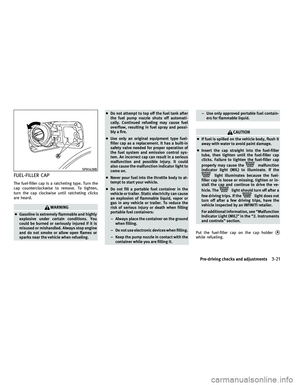
FUEL-FILLER CAP
The fuel-filler cap is a ratcheting type. Turn the
cap counterclockwise to remove. To tighten,
turn the cap clockwise until ratcheting clicks
are heard.
WARNING
cGasoline is extremely flammable and highly
explosive under certain conditions. You
could be burned or seriously injured if it is
misused or mishandled. Always stop engine
and do not smoke or allow open flames or
sparks near the vehicle when refueling. c
Do not attempt to top off the fuel tank after
the fuel pump nozzle shuts off automati-
cally. Continued refueling may cause fuel
overflow, resulting in fuel spray and possi-
bly a fire.
c Use only an original equipment type fuel-
filler cap as a replacement. It has a built-in
safety valve needed for proper operation of
the fuel system and emission control sys-
tem. An incorrect cap can result in a serious
malfunction and possible injury. It could
also cause the malfunction indicator light to
come on.
c Never pour fuel into the throttle body to at-
tempt to start your vehicle.
c Do not fill a portable fuel container in the
vehicle or trailer. Static electricity can cause
an explosion of flammable liquid, vapor or
gas in any vehicle or trailer. To reduce the
risk of serious injury or death when filling
portable fuel containers:
± Always place the container on the ground when filling.
± Do not use electronic devices when filling.
± Keep the pump nozzle in contact with the container while you are filling it. ± Use only approved portable fuel contain-
ers for flammable liquid.
CAUTION
cIf fuel is spilled on the vehicle body, flush it
away with water to avoid paint damage.
c Insert the cap straight into the fuel-filler
tube, then tighten until the fuel-filler cap
clicks. Failure to tighten the fuel-filler cap
properly may cause the
malfunction
indicator light (MIL) to illuminate. If the
light illuminates because the fuel-
filler cap is loose or missing, tighten or in-
stall the cap and continue to drive the ve-
hicle. The
light should turn off after a
few driving trips. If the
light does not
turn off after a few driving trips, have the
vehicle inspected by an INFINITI retailer.
For additional information, see ªMalfunction
Indicator Light (MIL)º in the ª2. Instruments
and controlsº section.
Put the fuel-filler cap on the cap holder
sA
while refueling.
SPA1428B
Pre-driving checks and adjustments3-21
wÐ
Ð
05/14/09Ðpattie
X
Page 158 of 445

MEMORY STORAGE
Two positions for the driver's seat, steering
column and outside mirrors can be stored in the
automatic drive positioner memory. Follow
these procedures to use the memory system.
1. Move the selector lever to the P (Park)position.
2. Push the ignition switch to the ON posi- tion. 3. Adjust the driver's seat, steering column
and outside mirrors to the desired posi-
tions by manually operating each adjust-
ing switch. For additional information, see
ªSEATSº in the ª1. Safety Ð Seats, seat
belts and supplemental restraint systemº
section and ªTILT/TELESCOPIC STEERINGº
page 3-22 and ªOUTSIDE MIRRORSº ear-
lier in this section.
4. Push the SET switch and, within 5 sec- onds, push the memory switch (1 or 2)
fully for at least 1 second.
The indicator light for the pushed memory
switch will stay on for approximately 5 sec-
onds after pushing the switch.
If memory is stored in the same memory switch,
the previous memory will be deleted.
Procedure for storing the outside
mirror positions for best visibility at
reverse tilt-down feature
Two outside mirror positions for backing up can
be stored in the automatic drive positioner
memory.
1. Apply the parking brake.
2. Push the ignition switch to the ON posi- tion. (Do not start the engine.) 3. Push the memory switch (1 or 2) fully for
at least 1 second to operate the automatic
drive positioner.
4. Turn the outside mirror control switch to L (left).
5. Depress the brake pedal.
6. Move the selector lever to the R (Reverse) position.
7. Adjust the mirror to the desired viewing position for backing up by operating the
outside mirror control switch.
8. Push the SET switch and, within 5 sec- onds, push the memory switch (1 or 2)
selected in step 3 fully for at least 1
second.
cThe indicator light for the pushed memory
switch will stay on for approximately 5
seconds after pushing the switch. After
the indicator light goes off, the selected
mirror position is stored in the selected
memory (1 or 2).
9. Turn the outside mirror control switch to R
(right).
Repeat the above procedure to adjust the
right mirror position and store in the se-
lected memory.
c When the driver's seat, outside mirror and
steering column are not in the memorized
SPA2020
Pre-driving checks and adjustments3-27
wÐ
Ð
05/14/09Ðpattie
X
Page 160 of 445

SYSTEM OPERATION
The automatic drive positioner system will not
work or will stop operating under the following
conditions:
cWhen the vehicle speed is above 4 MPH (7
km/h).
c When the adjusting switch for the driver's
seat and steering column is turned on while
the automatic drive positioner is operating.
c When the memory switch (1 or 2) is not
pushed for at least 1 second.
c When the seat, steering column and outside
mirrors have already been moved to the
memorized position.
c When no position is stored in the memory
switch.
c When the engine is started while the auto-
matic drive positioner is operating.
c When approximately 45 seconds have
passed after the driver's door was opened
(ignition switch is not in the ON position).
c When the selector lever is moved from the P
(Park) position to any other position. (How-
ever, it will not be canceled if the switch is
pushed while the seat and steering column
are returning to the previous positions
(entry/exit function).)
Pre-driving checks and adjustments3-29
wÐ
Ð
05/14/09Ðpattie
X
Page 166 of 445

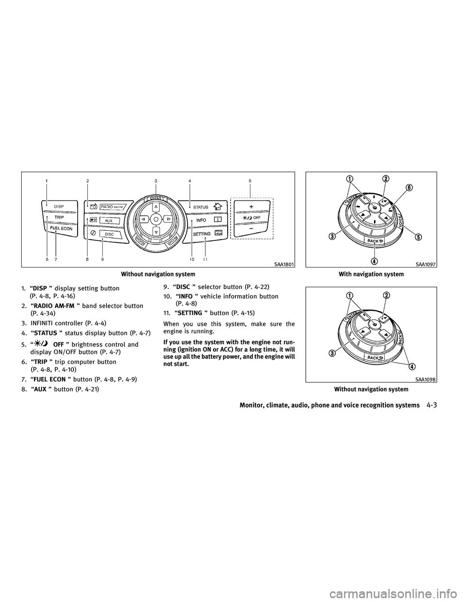
1. ªDISPº display setting button
(P. 4-8, P. 4-16)
2. ªRADIO AM´FM º band selector button
(P. 4-34)
3. INFINITI controller (P. 4-4)
4. ªSTATUS º status display button (P. 4-7)
5. ª
OFF º brightness control and
display ON/OFF button (P. 4-7)
6. ªTRIP º trip computer button
(P. 4-8, P. 4-10)
7. ªFUEL ECON º button (P. 4-8, P. 4-9)
8. ªAUX º button (P. 4-21) 9. ªDISC
º selector button (P. 4-22)
10. ª INFO º vehicle information button
(P. 4-8)
11. ª SETTING º button (P. 4-15)
When you use this system, make sure the
engine is running.
If you use the system with the engine not run-
ning (ignition ON or ACC) for a long time, it will
use up all the battery power, and the engine will
not start.
Without navigation system
SAA1801
With navigation system
SAA1097
Without navigation system
SAA1098
Monitor, climate, audio, phone and voice recognition systems4-3
wÐ
Ð
05/14/09Ðpattie
X