display INFINITI M 2010 Owners Manual
[x] Cancel search | Manufacturer: INFINITI, Model Year: 2010, Model line: M, Model: INFINITI M 2010Pages: 445, PDF Size: 6.15 MB
Page 17 of 445
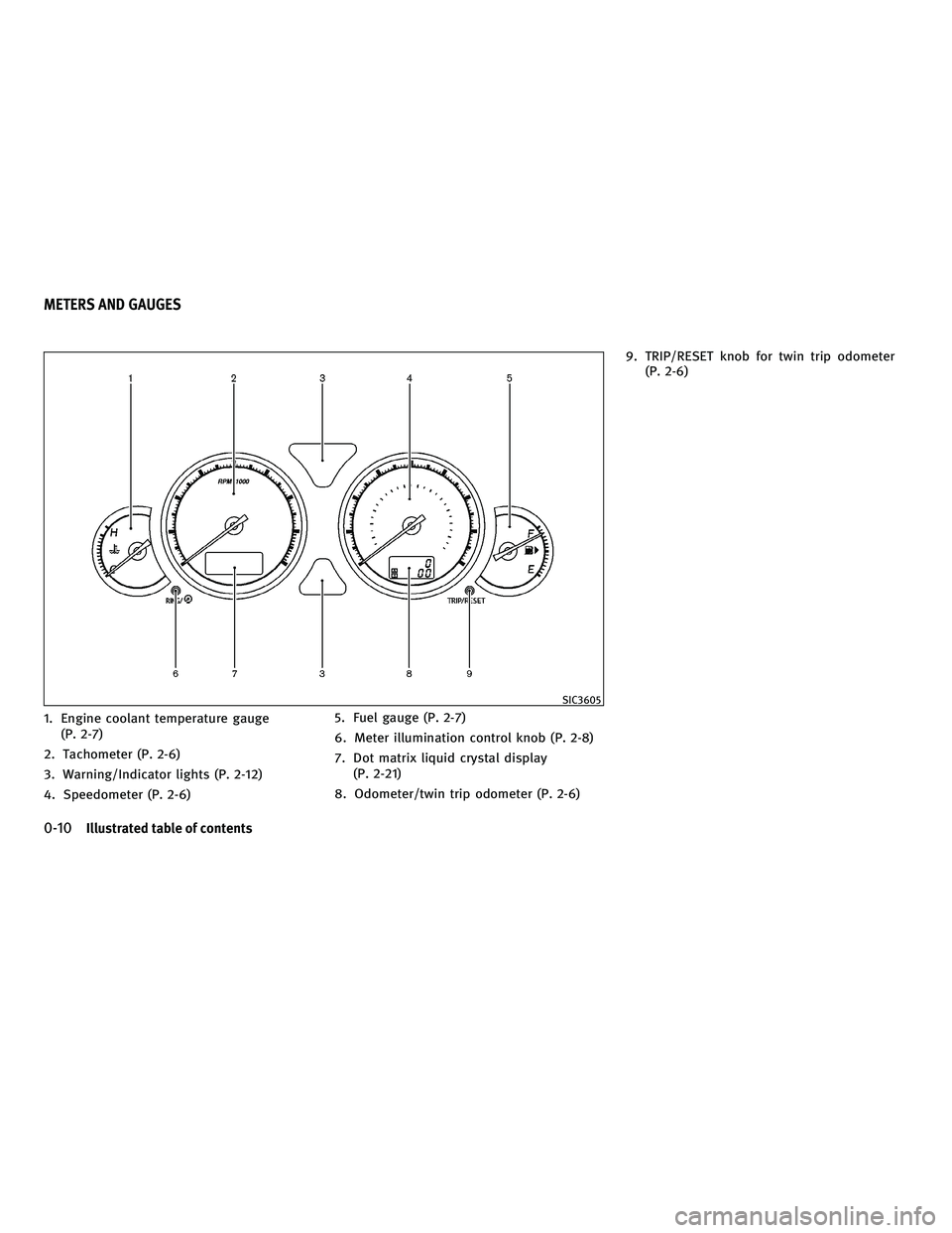
1. Engine coolant temperature gauge(P. 2-7)
2. Tachometer (P. 2-6)
3. Warning/Indicator lights (P. 2-12)
4. Speedometer (P. 2-6) 5. Fuel gauge (P. 2-7)
6. Meter illumination control knob (P. 2-8)
7. Dot matrix liquid crystal display
(P. 2-21)
8. Odometer/twin trip odometer (P. 2-6) 9. TRIP/RESET knob for twin trip odometer
(P. 2-6)
SIC3605
METERS AND GAUGES
0-10Illustrated table of contents
wÐ
Ð
05/19/09Ðtbrooks
X
Page 77 of 445
2 Instruments and controls
Cockpit........................................... 2-2
Instrument panel .................................. 2-3
Meters and gauges ................................ 2-5
Speedometer and odometer ..................... 2-6
Tachometer .................................... 2-6
Engine coolant temperature gauge ............... 2-7
Fuel gauge ..................................... 2-7
Meter/ring illumination and needle sweep ........ 2-8
Compass (if so equipped) .......................... 2-9
Zone variation change procedure ...............2-10
Warning/indicator lights and audible reminders .....2-12
Checking bulbs ............................... 2-13
Warning lights ................................ 2-13
Indicator lights ................................ 2-18
Audible reminders ............................. 2-20
Dot matrix liquid crystal display ...................2-21
Indicators for operation ........................ 2-22
Security systems ................................. 2-24
Vehicle security system ........................ 2-24
INFINITI Vehicle Immobilizer System ............2-25
Windshield wiper and washer switch ...............2-27
Rain-sensing auto wiper system ................2-28
Rear window and outside mirror defroster switch . . . 2-28 Headlight and turn signal switch
..................2-29
Xenon headlights ............................. 2-29
Headlight switch .............................. 2-29
Turn signal switch ............................. 2-33
Fog light switch ............................... 2-33
Hazard warning flasher switch .....................2-33
Horn ............................................ 2-34
Heated seats (rear seats) (if so equipped) ..........2-34
Climate controlled seats (front seats) ..............2-35
Lane Departure Warning (LDW) switch
(if so equipped) .................................. 2-36
SNOW mode switch (if so equipped) ...............2-37
Vehicle Dynamic Control (VDC) OFF switch ..........2-37
Clock ............................................ 2-38
Adjusting the time ............................. 2-38
Power outlets .................................... 2-38
Cigarette lighter and ashtrays .....................2-39
Front ......................................... 2-39
Rear ......................................... 2-39
Storage ......................................... 2-40
Cup holders .................................. 2-40
Sunglasses holder ............................. 2-41
Glove box .................................... 2-41
wÐ
Ð
05/19/09Ðtbrooks
X
Page 82 of 445
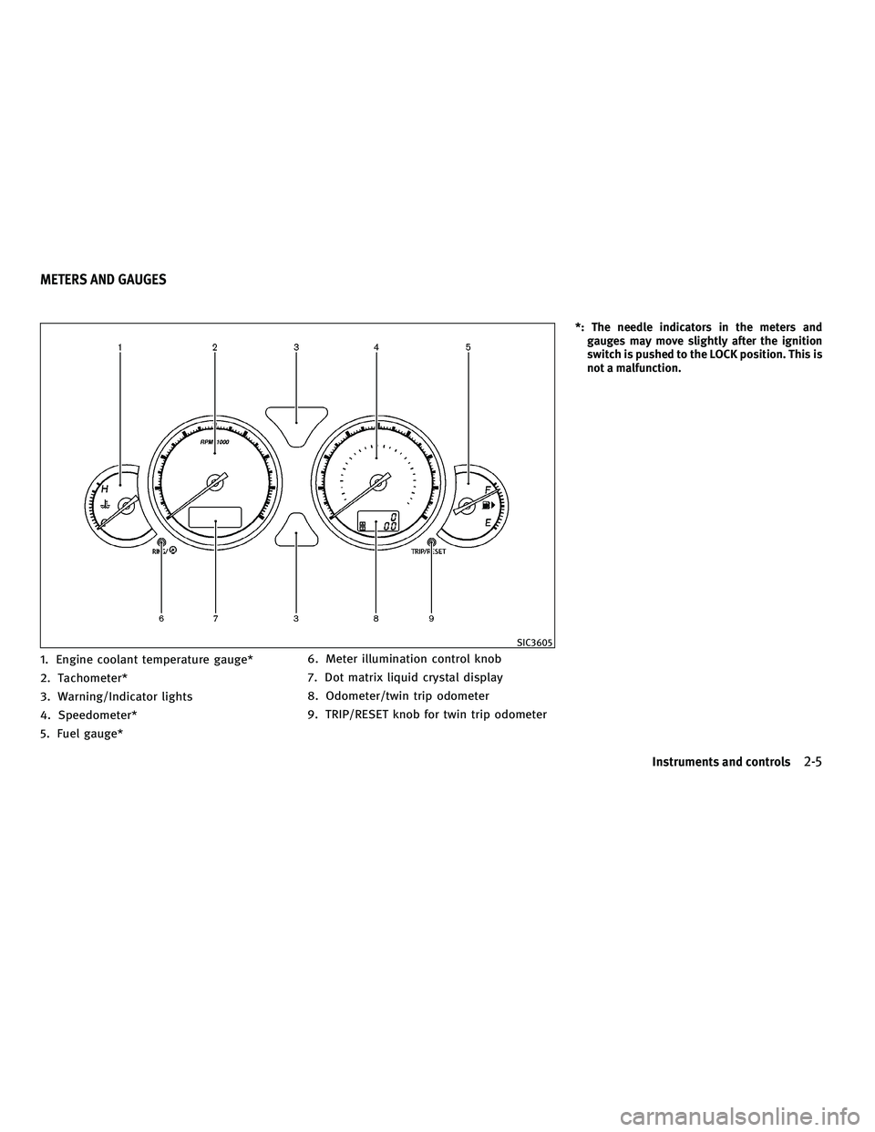
1. Engine coolant temperature gauge*
2. Tachometer*
3. Warning/Indicator lights
4. Speedometer*
5. Fuel gauge*6. Meter illumination control knob
7. Dot matrix liquid crystal display
8. Odometer/twin trip odometer
9. TRIP/RESET knob for twin trip odometer
*: The needle indicators in the meters and
gauges may move slightly after the ignition
switch is pushed to the LOCK position. This is
not a malfunction.
SIC3605
METERS AND GAUGES
Instruments and controls2-5
wÐ
Ð
05/19/09Ðtbrooks
X
Page 83 of 445
SPEEDOMETER AND ODOMETER
Speedometer
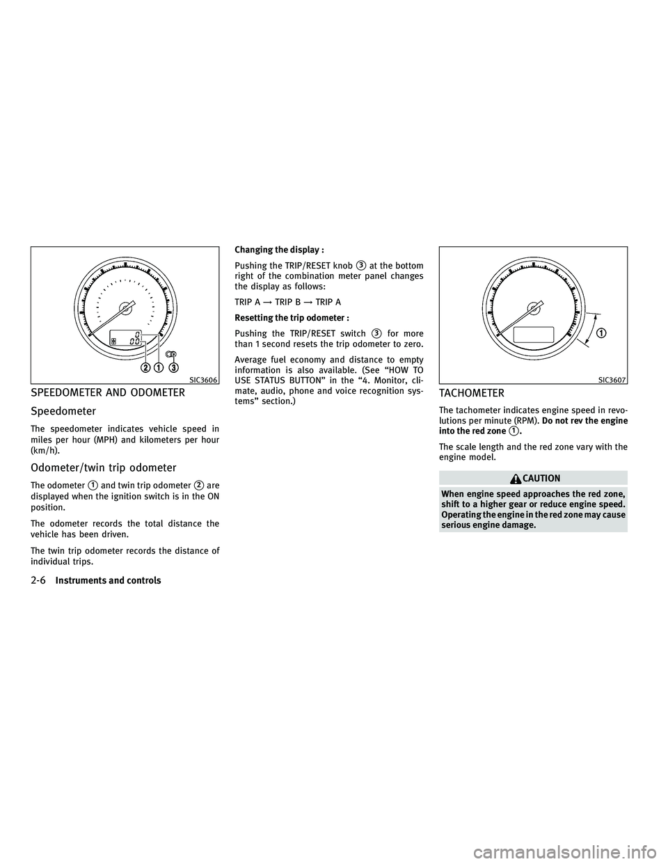
The speedometer indicates vehicle speed in
miles per hour (MPH) and kilometers per hour
(km/h).
Odometer/twin trip odometer
The odometers1and twin trip odometers2are
displayed when the ignition switch is in the ON
position.
The odometer records the total distance the
vehicle has been driven.
The twin trip odometer records the distance of
individual trips. Changing the display :
Pushing the TRIP/RESET knob
s3at the bottom
right of the combination meter panel changes
the display as follows:
TRIP A !TRIP B !TRIP A
Resetting the trip odometer :
Pushing the TRIP/RESET switch
s3for more
than 1 second resets the trip odometer to zero.
Average fuel economy and distance to empty
information is also available. (See ªHOW TO
USE STATUS BUTTONº in the ª4. Monitor, cli-
mate, audio, phone and voice recognition sys-
temsº section.)
TACHOMETER
The tachometer indicates engine speed in revo-
lutions per minute (RPM). Do not rev the engine
into the red zone
s1.
The scale length and the red zone vary with the
engine model.
CAUTION
When engine speed approaches the red zone,
shift to a higher gear or reduce engine speed.
Operating the engine in the red zone may cause
serious engine damage.
SIC3606SIC3607
2-6Instruments and controls
wÐ
Ð
05/19/09Ðtbrooks
X
Page 86 of 445

When the ignition switch is pushed to the ON
position, the compass display
sBwill indicate
the direction of the vehicle's heading.
If the display reads ªCº, calibrate the compass
by driving the vehicle in 3 complete circles at
less than 5 MPH (8 km/h). You can also cali-
brate the compass by driving your vehicle on
your everyday route. The compass will be cali-
brated once it has tracked 3 complete circles.
To turn on and off the compass manually, push
the
switchsAwhile the ignition switch is
in the ON position.
SIC3181
COMPASS (if so equipped)
Instruments and controls2-9
wÐ
Ð
05/14/09Ðpattie
X
Page 87 of 445

ZONE VARIATION CHANGE
PROCEDURE
The difference between magnetic north and
geographical north is known as variance. In
some areas, this difference can sometimes be
great enough to cause false compass readings.
Follow these instructions to set the variance for
your particular location if this happens:
1. Push theswitch for more than 3
seconds. The current zone number will
appear in the display.
2. Find your current location and variance number on the zone map.
NOTE:
Use zone number 5 for Hawaii.
3. Push theswitch repeatedly until
the new zone number appears in the
display, then release the switch. After you
release the switch, the display will show a
compass direction within a few seconds.
c If the compass deviates from the correct
indication soon after repeated adjustment,
have the compass checked at an INFINITI
retailer.
c The compass may not indicate the correct
compass point in tunnels or while driving up
Zone map
SIC0611B
2-10Instruments and controls
wÐ
Ð
05/14/09Ðpattie
X
Page 93 of 445
After the ignition switch is pushed ON, this light
illuminates for about 1 second and turns off.
Low tire pressure warning :
If the vehicle is being driven with low tire
pressure, the warning light will illuminate. If
you select the tire pressure information in the
display, the LOW PRESSURE information will be
displayed. The tire pressure for each tire will
also be displayed.
When the low tire pressure warning light illumi-
nates, you should stop and adjust the tire
pressure to the recommended COLD tire pres-
sure shown on the Tire and Loading Information
label. The low tire pressure warning light does
not automatically turn off when the tire pres-
sure is adjusted. After the tire is inflated to the
recommended pressure, the vehicle must be
driven at speeds above 16 MPH (25 km/h) to
activate the TPMS and turn off the low tire
pressure warning light. Use a tire pressure
gauge to check the tire pressure.
For additional information, see ªTIRE PRESSURE
MONITORING SYSTEM (TPMS)º in the ª5. Start-
ing and drivingº section and ªTIRE PRESSURE
MONITORING SYSTEM (TPMS)º in the ª6. In case
of emergencyº section. For the tire pressure
information display, see ªHOW TO USE INFO
BUTTONº in the ª4. Monitor, climate, audio,
phone and voice recognition systemsº section.TPMS malfunction :
If the TPMS is not functioning properly, the low
tire pressure warning light will flash for approxi-
mately 1 minute when the ignition switch is
pushed ON. The light will remain on after 1
minute. Have the system checked by an INFINITI
retailer.
For additional information, see ªTIRE PRESSURE
MONITORING SYSTEM (TPMS)º in the ª5. Start-
ing and drivingº section.
WARNING
c
If the light does not illuminate with the igni-
tion switch pushed ON, have the vehicle
checked by an INFINITI retailer as soon as
possible. c
If the light illuminates while driving, avoid
sudden steering maneuvers or abrupt brak-
ing, reduce vehicle speed, pull off the road to
a safe location and stop the vehicle as soon
as possible. Driving with under-inflated tires
may permanently damage the tires and in-
crease the likelihood of tire failure. Serious
vehicle damage could occur and may lead to
an accident and could result in serious per-
sonal injury. Check the tire pressure for all
four tires. Adjust the tire pressure to the rec-
ommended COLD tire pressure shown on the
Tire and Loading Information label to turn
the low tire pressure warning light OFF. If the
light stays on after adjusting the tire pres-
sure and driving over 16 MPH (25 km/h), have
the system checked by an INFINITI retailer. If
you have a flat tire, replace it with a spare
tire as soon as possible.
c When a spare tire is mounted or a wheel is
replaced, tire pressure will not be indicated,
the TPMS will not function and the low tire
pressure warning light will flash for approxi-
mately 1 minute. The light will remain on
after 1 minute. Contact your INFINITI retailer
as soon as possible for tire replacement
and/or system resetting.
2-16Instruments and controls
wÐ
Ð
05/14/09Ðpattie
X
Page 98 of 445

pedal is not depressed. Have the brakes
checked as soon as possible if the warning
sound is heard.
Lane departure warning chime (if so
equipped)
When the Lane Departure Warning (LDW) or
Lane Departure Prevention (LDP) system is on,
the chime sounds if the vehicle is traveling
close to either the left or the right of a traveling
lane with detectable lane markers.
See ªLANE DEPARTURE WARNING (LDW)
SYSTEM/LANE DEPARTURE PREVENTION (LDP)
SYSTEMº in the ª5. Starting and drivingº sec-
tion for more details.The dot matrix liquid crystal display
s1is
located under the tachometer, and it displays
the Automatic Transmission (AT) position indi-
cator, the Intelligent Cruise Control (ICC) system
(if so equipped) information and the Intelligent
Key operation information.
For detailed information about each system, see
the following sections:
c Automatic Transmission (AT)
± ªWARNING/INDICATOR LIGHTS AND AU- DIBLE REMINDERSº earlier in this section.
± ªDRIVING THE VEHICLEº in the ª5. Start- ing and drivingº section. c
Intelligent Cruise Control (ICC) system
± ªINTELLIGENT CRUISE CONTROL (ICC) SYSTEMº in the ª5. Starting and drivingº
section.
c Intelligent Key system
± ªINTELLIGENT KEY SYSTEMº in the ª3. Pre-driving checks and adjustmentsº sec-
tion.
± ªPUSH-BUTTON IGNITION SWITCHº in the ª5. Starting and drivingº section.
SIC3611
DOT MATRIX LIQUID CRYSTAL DISPLAY
Instruments and controls2-21
wÐ
Ð
05/19/09Ðtbrooks
X
Page 115 of 445

If the power supply is disconnected, the clock
will not indicate the correct time. Readjust the
time.
ADJUSTING THE TIME
1. To set the clock forward, push the button
s1.
2. To set the clock backward, push the but- ton
s2.
3. To move forward or backward faster, push and hold the button more than 5 seconds.
For details about display clock adjustment (if so
equipped), see ªHOW TO USE SETTING BUTTONº
in the ª4. Monitor, climate, audio, phone and
voice recognition systemsº section. The power outlets are located on the back side
and inside (if equipped) of the center console
for powering electrical accessories such as a
cellular telephone.
CAUTION
c
The outlet and plug may be hot during or
immediately after use.
c Do not use with accessories that exceed a 12
volt, 120W (10A) power draw. Do not use
double adapters or more than one electrical
accessory.
c Use power outlet with the engine running to
avoid discharging the vehicle battery.
c Avoid using power outlet when the air condi-
tioner, headlights or rear window defroster
is on.
c This power outlet is not designed for use
with a cigarette lighter unit.
c Push the plug in as far as it will go. If good
contact is not made, the plug may overheat
or the internal temperature fuse may open.
c Before inserting or disconnecting a plug, be
sure the electrical accessory being used is
turned OFF.
c When not in use, be sure to close the cap. Do
not allow water to contact the outlet.
SIC2772SIC2773
Only for model without DVD player
SIC2774
CLOCK POWER OUTLETS
2-38Instruments and controls
wÐ
Ð
05/14/09Ðpattie
X
Page 142 of 445

Opening trunk lid
1. Push the trunk open request switchsAfor
more than 1 second.
2. The trunk will unlatch. An outside chime will sound four times.
3. Raise the trunk lid to open the trunk.
Lockout protection :
To prevent the Intelligent Key from being acci-
dentally locked in the trunk, lockout protection
is equipped with the Intelligent Key system.
When the trunk lid is closed with the Intelligent
Key inside the trunk, the outside buzzer will
sound and the trunk will open.
BATTERY SAVER SYSTEM
When all the following conditions are met for 60
minutes, the battery saver system will cut off
the power supply to prevent battery discharge.
c The ignition switch is in the ACC position,
and
c All doors are closed, and
c The selector lever is in the P (Park) position.
WARNING SIGNALS
To help prevent the vehicle from moving unex-
pectedly by erroneous operation of the Intelli-
gent Key listed on the following chart or to help
prevent the vehicle from being stolen, chime or
beep sounds inside and outside the vehicle and
a warning displays in the dot matrix liquid
crystal display.
When a chime or beep sounds or the warning
displays, be sure to check the vehicle and
Intelligent Key.
See ªTROUBLESHOOTING GUIDEº later in this
section and ªDOT MATRIX LIQUID CRYSTAL DIS-
PLAYº in the ª2. Instruments and controlsº
section.
SPA2426
SPA2427
Pre-driving checks and adjustments3-11
wÐ
Ð
05/14/09Ðpattie
X