Crankshaft Position Sensor INFINITI M35 2006 Factory Service Manual
[x] Cancel search | Manufacturer: INFINITI, Model Year: 2006, Model line: M35, Model: INFINITI M35 2006Pages: 5621, PDF Size: 65.56 MB
Page 351 of 5621

from the A/")
AT-272
TRANSMISSION ASSEMBLY
Revision: 2006 January2006 M35/M45
VK45DE models
REMOVAL
CAUTION:
When removing the A/T assembly from engine, first remove the crankshaft position sensor (POS)
from the A/T assembly.
Be careful not to damage sensor edge.
1. Disconnect the battery cable from the negative terminal.
2. Remove engine under cover with power tool.
3. Remove A/T fluid level gauge.
4. Remove exhaust front tube and center muffler with power tool. Refer to EX-5, "
Removal and Installation"
(for VQ35DE engine), EX-7, "Removal and installation" (for VK45DE engine).
5. Remove heat insulator.
6. Remove rear propeller shaft. Refer to PR-8, "
Removal and Installation" .
7. Remove rack stay. Refer to FSU-9, "
Removal and Installation" .
8. Remove exhaust mounting bracket. Refer to EX-5, "
Removal and Installation" (for VQ35DE engine), EX-
7, "Removal and installation" (for VK45DE engine).
9. Remove control rod. Refer to AT-226, "
Control Rod Removal and Installation" .
SCIA7320E
1. A/T assembly 2. A/T fluid level gauge 3. A/T fluid charging pipe
4. O-ring 5. Copper washer 6. Fluid cooler tube
7. Bracket 8. Rear engine mounting member 9. Engine mounting insulator (rear)
Refer to GI section to make sure icons (symbol marks) in the figure. Refer to GI-11, "
Components" .
However, refer to following symbols for others.
:For tightening torque, refer to AT-274, "
INSTALLATION" .
Page 352 of 5621
 (1) from A/T assem-
bly.
CAUTION:
Do not subject it to impact b")
TRANSMISSION ASSEMBLY
AT-273
D
E
F
G
H
I
J
K
L
MA
B
AT
Revision: 2006 January2006 M35/M45
10. Remove crankshaft position sensor (POS) (1) from A/T assem-
bly.
CAUTION:
Do not subject it to impact by dropping or hitting it.
Do not disassemble.
Do not allow metal filings, etc., to get on the sensor's
front edge magnetic area.
Do not place in an area affected by magnetism.
11. Remove starter motor. Refer to SC-17, "
VQ35DE ENGINE
MODELS (2WD)" , SC-19, "VK45DE ENGINE MODELS" .
12. Remove rear cover plate. Refer to EM-29, "
Removal and Instal-
lation (2WD Models)" (for VQ35DE engine).
13. Remove rear plate cover. Refer to EM-29, "
Removal and Installation (2WD Models)" (for VQ35DE
engine), EM-187, "
Removal and Installation" (for VK45DE engine).
14. Turn crankshaft, and remove the four tightening bolts for drive
plate and torque converter.
CAUTION:
When turning the crankshaft, turn it clockwise as viewed
from the front of the engine.
15. Support A/T assembly with a transmission jack.
CAUTION:
When setting the transmission jack, be careful not to allow
it to collide against the drain plug.
16. Remove rear engine mounting member with power tool.
17. Remove engine mounting insulator (rear).
18. Disconnect A/T assembly harness connector.
19. Remove air breather hose. Refer to AT-269, "
Removal and Installation" .
20. Remove A/T fluid charging pipe from A/T assembly.
21. Remove O-ring from A/T fluid charging pipe.
22. Disconnect fluid cooler tube from A/T assembly.
23. Plug up openings such as the A/T fluid charging pipe hole, etc.
24. Remove bolts fixing A/T assembly to engine assembly with power tool.
25. Remove A/T assembly from vehicle.
CAUTION:
Secure torque converter to prevent it from dropping.
Secure A/T assembly to a transmission jack.
SCIA6506J
LCIA0335E
SCIA0499E
Page 354 of 5621
TRANSMISSION ASSEMBLY
AT-275
D
E
F
G
H
I
J
K
L
MA
B
AT
Revision: 2006 January2006 M35/M45
Install crankshaft position sensor (POS). Refer to EM-29, "Removal and Installation (2WD Models)" (for
VQ35DE engine), EM-187, "
Removal and Installation" (for VK45DE engine).
After completing installation, check A/T fluid leakage, A/T fluid level and A/T position. Refer to AT- 1 3 ,
"Checking A/T Fluid" , AT-228, "Checking of A/T Position" .
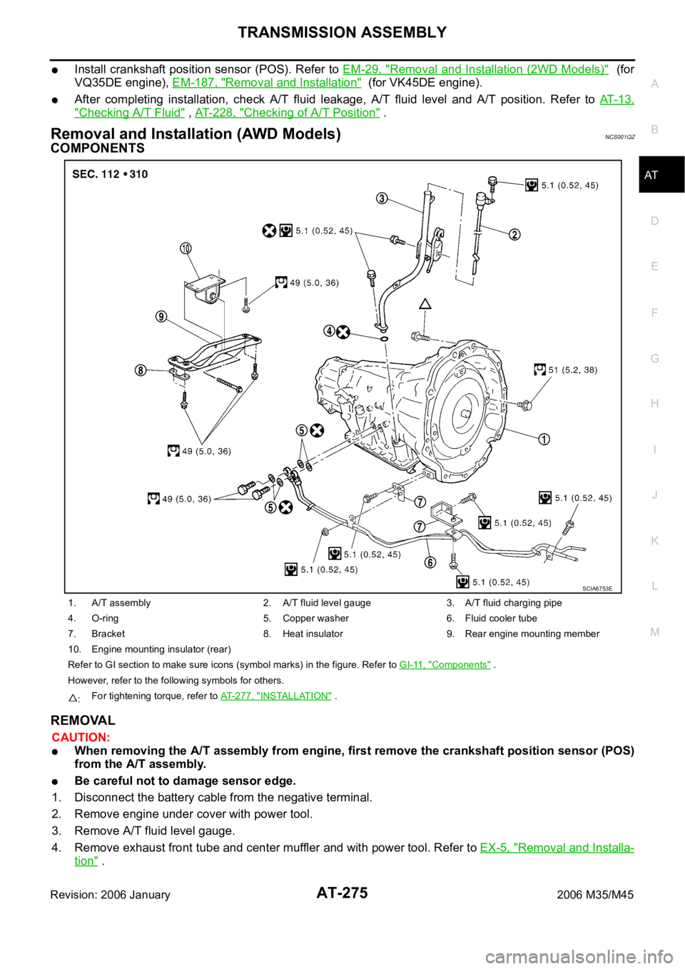
Removal and Installation (AWD Models) NCS001QZ
COMPONENTS
REMOVAL
CAUTION:
When removing the A/T assembly from engine, first remove the crankshaft position sensor (POS)
from the A/T assembly.
Be careful not to damage sensor edge.
1. Disconnect the battery cable from the negative terminal.
2. Remove engine under cover with power tool.
3. Remove A/T fluid level gauge.
4. Remove exhaust front tube and center muffler and with power tool. Refer to EX-5, "
Removal and Installa-
tion" .
1. A/T assembly 2. A/T fluid level gauge 3. A/T fluid charging pipe
4. O-ring 5. Copper washer 6. Fluid cooler tube
7. Bracket 8. Heat insulator 9. Rear engine mounting member
10. Engine mounting insulator (rear)
Refer to GI section to make sure icons (symbol marks) in the figure. Refer to GI-11, "
Components" .
However, refer to the following symbols for others.
:For tightening torque, refer to AT-277, "
INSTALLATION" .
SCIA6753E
Page 355 of 5621

AT-276
TRANSMISSION ASSEMBLY
Revision: 2006 January2006 M35/M45
5. Remove heat insulator.
6. Remove rear propeller shaft. Refer to PR-8, "
Removal and Installation" .
7. Remove front cross bar with power tool. Refer to FSU-26, "
Removal and Installation" .
8. Remove exhaust mounting bracket. Refer to EX-5, "
Removal and Installation" .
9. Remove three way catalyst. Refer to EX-5, "
Removal and Installation" .
10. Remove front propeller shaft. Refer to PR-5, "
Removal and Installation" .
11. Remove control rod. Refer to AT-226, "
Control Rod Removal and Installation" .
12. Remove crankshaft position sensor (POS) (1) from A/T assem-
bly.
CAUTION:
Do not subject it to impact by dropping or hitting it.
Do not disassemble.
Do not allow metal filings, etc., to get on the sensor's
front edge magnetic area.
Do not place in an area affected by magnetism.
13. Remove starter motor. Refer to SC-18, "
VQ35DE ENGINE
MODELS (AWD)" .
14. Remove rear plate cover. Refer to EM-36, "
Removal and Instal-
lation (AWD Models)" .
15. Turn crankshaft, and remove the four tightening bolts for drive
plate and torque converter.
CAUTION:
When turning the crankshaft, turn it clockwise as viewed
from the front of the engine.
16. Support A/T assembly with a transmission jack.
CAUTION:
When setting the transmission jack, be careful not to allow
it to collide against the drain plug.
17. Remove rear engine mounting member with power tool.
18. Remove engine mounting insulator (rear).
19. Disconnect A/T assembly harness connector.
20. Remove air breather hose. Refer to AT- 2 6 9 , "
Removal and Installation" .
21. Remove A/T fluid charging pipe from A/T assembly.
22. Remove O-ring from A/T fluid charging pipe.
23. Disconnect fluid cooler tube from the A/T assembly.
24. Plug up openings such as the A/T fluid charging pipe hole, etc.
25. Remove bolts fixing A/T assembly to engine assembly with power tool.
26. Remove A/T assembly with transfer assembly from vehicle.
CAUTION:
Secure torque converter to prevent it from dropping.
Secure A/T assembly to a transmission jack.
27. Remove transfer assembly from A/T assembly with power tool.
SCIA6506J
LCIA0335E
SCIA2203E
Page 356 of 5621

TRANSMISSION ASSEMBLY
AT-277
D
E
F
G
H
I
J
K
L
MA
B
AT
Revision: 2006 January2006 M35/M45
INSPECTION
Installation and Inspection of Torque Converter
After inserting a torque converter to a A/T, be sure to check dis-
tance “A” to ensure it is within the reference value limit.
INSTALLATION
Install the removed parts in the reverse order of the removal, while paying attention to the following work.
When installing A/T assembly to the engine assembly, attach the
fixing bolts in accordance with the following standard.
Align the positions of tightening bolts for drive plate with those of
the torque converter, and temporarily tighten the bolts. Then,
tighten the bolts with the specified torque. Refer to AT- 2 7 5 ,
"COMPONENTS" .
CAUTION:
When turning crankshaft, turn it clockwise as viewed from
the front of the engine.
When tightening the tightening bolts for the torque con-
verter after fixing the crankshaft pulley bolts, be sure to
confirm the tightening torque of the crankshaft pulley
mounting bolts. Refer to EM-72, "
INSTALLATION" .
After converter is installed to drive plate, rotate crankshaft
several turns and check to be sure that A/T rotates freely without binding.
Install crankshaft position sensor (POS). Refer to EM-36, "Removal and Installation (AWD Models)" .
After completing installation, check A/T fluid leakage, A/T fluid level and A/T position. Refer to AT- 1 3 ,
"Checking A/T Fluid" , AT-228, "Checking of A/T Position" . Distance “A”: 25.0 mm (0.98 in) or more
SCIA5694E
Bolt No. 1 2 3 4
Number of bolts 1 5 2 1
Bolt length
“ ”mm (in)55 (2.17) 65 (2.56) 35 (1.38) 40 (1.57)
Tightening torque
Nꞏm (kg-m, ft-lb)75
(7.7, 55)47
(4.8, 35)34
(3.5, 25)
SCIA4600E
SCIA2288E
Page 1439 of 5621
 converses a pulse signal from wheel se")
DI-6
COMBINATION METERS
Revision: 2006 January2006 M35/M45
SPEEDOMETER
The speedometer indicates the vehicle speed.
ABS actuator and electric unit (control unit) converses a pulse signal from wheel sensor to vehicle speed
signal, and transmit vehicle speed signal to unified meter and A/C amp. with CAN communication.
Unified meter and A/C amp. transmits vehicle speed signal to combination meter with communication line.
Combination meter converses vehicle speed signal to the angle signal, and commands to speedometer.
TACHOMETER
The tachometer indicates engine speed in revolutions per minute (rpm).
ECM converses a signal from crankshaft position sensor to engine speed signal, and transmits to unified
meter and A/C amp. with CAN communication.
Unified meter and A/C amp. transmits engine speed signal to combination meter with communication line.
Combination meter converses engine speed signal to the angle signal, and commands to tachometer.
WATER TEMPERATURE GAUGE
The water temperature gauge indicates the engine coolant temperature.
ECM converses a signal from engine coolant temperature sensor to engine coolant temperature signal,
and transmits to unified meter and A/C amp. with CAN communication.
Unified meter and A/C amp. transmits engine coolant temperature signal to combination meter with com-
munication line.
Combination meter converses engine coolant temperature signal to the angle signal, and commands to
water temperature gauge.
PKIC0696E
PKIB7631E
PKIB7632E
Page 1551 of 5621

EC-8Revision: 2006 January2006 M35/M45 Wiring Diagram .....................................................708
Diagnostic Procedure ...........................................709
Component Inspection ..........................................713
ASCD INDICATOR .................................................
.714
Component Description ........................................714
CONSULT-II Reference Value in Data Monitor Mode
.714
Wiring Diagram .....................................................715
Diagnostic Procedure ...........................................716
SNOW MODE SWITCH ...........................................717
Description ............................................................717
CONSULT-II Reference Value in the Data Monitor
Mode .....................................................................717
Wiring Diagram .....................................................718
Diagnostic Procedure ...........................................719
Component Inspection ..........................................721
MIL AND DATA LINK CONNECTOR ......................722
Wiring Diagram .....................................................722
SERVICE DATA AND SPECIFICATIONS (SDS) ....724
Fuel Pressure .......................................................724
Idle Speed and Ignition Timing .............................724
Calculated Load Value ..........................................724
Mass Air Flow Sensor ...........................................724
Intake Air Temperature Sensor .............................724
Engine Coolant Temperature Sensor ...................724
Fuel Tank Temperature Sensor ............................724
Crankshaft Position Sensor (POS) .......................724
Camshaft Position Sensor (PHASE) ....................724
A/F Sensor 1 Heater ............................................ .724
Heated Oxygen Sensor 2 Heater .........................725
Throttle Control Motor ...........................................725
Fuel Injector ..........................................................725
Fuel Pump ............................................................725
VK45DE
INDEX FOR DTC .....................................................726
DTC No. Index ......................................................726
Alphabetical Index ................................................730
PRECAUTIONS .......................................................734
Precautions for Supplemental Restraint System
(SRS) “AIR BAG” and “SEAT BELT PRE-TEN-
SIONER” ...............................................................734
Precautions for Procedures without Cowl Top Cover .734
On Board Diagnostic (OBD) System of Engine and
A/T ........................................................................734
Precaution ............................................................735
PREPARATION .......................................................738
Special Service Tools ...........................................738
Commercial Service Tools ....................................739
ENGINE CONTROL SYSTEM ................................740
System Diagram ...................................................740
Multiport Fuel Injection (MFI) System ...................741
Electronic Ignition (EI) System .............................743
Fuel Cut Control (At No Load and High Engine
Speed) ..................................................................744
AIR CONDITIONING CUT CONTROL ....................745
Input/Output Signal Chart .....................................745
System Description ...............................................745AUTOMATIC SPEED CONTROL DEVICE (ASCD) .746
System Description ...............................................746
Component Description ........................................747
CAN COMMUNICATION .........................................748
System Description ...............................................748
EVAPORATIVE EMISSION SYSTEM .....................749
Description ............................................................749
Component Inspection ..........................................752
Removal and Installation .......................................753
How to Detect Fuel Vapor Leakage ......................753
ON BOARD REFUELING VAPOR RECOVERY
(ORVR) ....................................................................756
System Description ...............................................756
Diagnostic Procedure ............................................757
Component Inspection ..........................................759
POSITIVE CRANKCASE VENTILATION ................761
Description ............................................................761
Component Inspection ..........................................761
IVIS (INFINITI VEHICLE IMMOBILIZER SYSTEM-
NATS) ......................................................................763
Description ............................................................763
ON BOARD DIAGNOSTIC (OBD) SYSTEM ...........764
Introduction ..........................................................
.764
Two Trip Detection Logic .......................................764
Emission-Related Diagnostic Information .............765
Malfunction Indicator Lamp (MIL) .........................780
OBD System Operation Chart ...............................782
BASIC SERVICE PROCEDURE .............................788
Basic Inspection ....................................................788
Idle Speed and Ignition Timing Check ..................793
Idle Mixture Ratio Adjustment ...............................795
VIN Registration ....................................................806
Accelerator Pedal Released Position Learning .....806
Throttle Valve Closed Position Learning ...............806
Idle Air Volume Learning .......................................807
Fuel Pressure Check ............................................809
TROUBLE DIAGNOSIS ..........................................811
Trouble Diagnosis Introduction .............................811
DTC Inspection Priority Chart ...............................817
Fail-Safe Chart ......................................................819
Symptom Matrix Chart ..........................................820
Engine Control Component Parts Location ...........824
Vacuum Hose Drawing .........................................833
Circuit Diagram .....................................................834
ECM Harness Connector Terminal Layout ............836
ECM Terminals and Reference Value ...................836
CONSULT-II Function (ENGINE) ..........................846
Generic Scan Tool (GST) Function .......................859
CONSULT-II Reference Value in Data Monitor .....862
Major Sensor Reference Graph in Data Monitor
Mode .....................................................................866
TROUBLE DIAGNOSIS - SPECIFICATION VALUE .868
Description ............................................................868
Testing Condition ..................................................868
Inspection Procedure ...........................................
.868
Diagnostic Procedure ............................................869
TROUBLE DIAGNOSIS FOR INTERMITTENT INCI-
Page 1558 of 5621

EC-15
C
D
E
F
G
H
I
J
K
L
M
ECA
Revision: 2006 January2006 M35/M45 FUEL PUMP ..........................................................1427
Description ..........................................................1427
CONSULT-II Reference Value in Data Monitor Mode
1427
Wiring Diagram ...................................................1428
Diagnostic Procedure ..........................................1429
Component Inspection ........................................1433
Removal and Installation .....................................1433
REFRIGERANT PRESSURE SENSOR ................1434
Component Description .......................................1434
Wiring Diagram ...................................................1435
Diagnostic Procedure ..........................................1436
Removal and Installation .....................................1438
ELECTRICAL LOAD SIGNAL ...............................1439
Description ..........................................................1439
CONSULT-II Reference Value in Data Monitor Mode
1439
Diagnostic Procedure ..........................................1439
ICC BRAKE SWITCH ............................................1441
Component Description .......................................1441
CONSULT-II Reference Value in Data Monitor Mode
1441
Wiring Diagram ...................................................1442
Diagnostic Procedure ..........................................1443
Component Inspection ........................................1447
ASCD BRAKE SWITCH ........................................1449
Component Description .......................................1449
CONSULT-II Reference Value in Data Monitor Mode 1449
Wiring Diagram ....................................................1450
Diagnostic Procedure ..........................................1451
Component Inspection .........................................1455
ASCD INDICATOR ................................................. 1456
Component Description .......................................1456
CONSULT-II Reference Value in Data Monitor Mode
1456
Wiring Diagram ....................................................1457
Diagnostic Procedure ..........................................1458
MIL AND DATA LINK CONNECTOR .....................1459
Wiring Diagram ....................................................1459
SERVICE DATA AND SPECIFICATIONS (SDS) ...1461
Fuel Pressure ......................................................1461
Idle Speed and Ignition Timing ............................1461
Calculated Load Value .........................................1461
Mass Air Flow Sensor ..........................................1461
Intake Air Temperature Sensor ............................1461
Engine Coolant Temperature Sensor ..................1461
Fuel Tank Temperature Sensor ...........................1461
Crankshaft Position Sensor (POS) ......................1461
Camshaft Position Sensor (PHASE) ...................1461
A/F Sensor 1 Heater ............................................ 1461
Heated Oxygen Sensor 2 Heater ........................1462
Throttle Control Motor ..........................................1462
Fuel Injector .........................................................1462
Fuel Pump ...........................................................1462
Page 1569 of 5621
![INFINITI M35 2006 Factory Service Manual EC-26
[VQ35DE]
PRECAUTIONS
Revision: 2006 January2006 M35/M45
Before replacing ECM, perform ECM Terminals and Refer-
ence Value inspection and make sure ECM functions prop-
erly. Refer](/img/42/57023/w960_57023-1568.png "INFINITI M35 2006 Factory Service Manual EC-26
[VQ35DE]
PRECAUTIONS
Revision: 2006 January2006 M35/M45
Before replacing ECM, perform ECM Terminals and Refer-
ence Value inspection and make sure ECM functions prop-
erly. Refer")
EC-26
[VQ35DE]
PRECAUTIONS
Revision: 2006 January2006 M35/M45
Before replacing ECM, perform ECM Terminals and Refer-
ence Value inspection and make sure ECM functions prop-
erly. Refer to EC-124, "
ECM Harness Connector Terminal
Layout" .
Handle mass air flow sensor carefully to avoid damage.
Do not clean mass air flow sensor with any type of deter-
gent.
Do not disassemble electric throttle control actuator.
Even a slight leak in the air intake system can cause seri-
ous incidents.
Do not shock or jar the camshaft position sensor (PHASE),
crankshaft position sensor (POS).
After performing each TROUBLE DIAGNOSIS, perform DTC
Confirmation Procedure or Overall Function Check.
The DTC should not be displayed in the DTC Confirmation
Procedure if the repair is completed. The Overall Function
Check should be a good result if the repair is completed.
When measuring ECM signals with a circuit tester, never
allow the two tester probes to contact.
Accidental contact of probes will cause a short circuit and
damage the ECM power transistor.
Do not use ECM ground terminals when measuring input/
output voltage. Doing so may result in damage to the ECM's
transistor. Use a ground other than ECM terminals, such as
the ground.
MEF040D
SEF217U
SEF348N
Page 1574 of 5621
![INFINITI M35 2006 Factory Service Manual ENGINE CONTROL SYSTEM
EC-31
[VQ35DE]
C
D
E
F
G
H
I
J
K
L
MA
EC
Revision: 2006 January2006 M35/M45
Multiport Fuel Injection (MFI) SystemNBS004S3
INPUT/OUTPUT SIGNAL CHART
*1: This sensor is not used to](/img/42/57023/w960_57023-1573.png "INFINITI M35 2006 Factory Service Manual ENGINE CONTROL SYSTEM
EC-31
[VQ35DE]
C
D
E
F
G
H
I
J
K
L
MA
EC
Revision: 2006 January2006 M35/M45
Multiport Fuel Injection (MFI) SystemNBS004S3
INPUT/OUTPUT SIGNAL CHART
*1: This sensor is not used to")
ENGINE CONTROL SYSTEM
EC-31
[VQ35DE]
C
D
E
F
G
H
I
J
K
L
MA
EC
Revision: 2006 January2006 M35/M45
Multiport Fuel Injection (MFI) SystemNBS004S3
INPUT/OUTPUT SIGNAL CHART
*1: This sensor is not used to control the engine system under normal conditions.
*2: This signal is sent to the ECM through CAN communication line.
*3: ECM determines the start signal status by the signals of engine speed and battery voltage.
SYSTEM DESCRIPTION
The amount of fuel injected from the fuel injector is determined by the ECM. The ECM controls the length of
time the valve remains open (injection pulse duration). The amount of fuel injected is a program value in the
ECM memory. The program value is preset by engine operating conditions. These conditions are determined
by input signals (for engine speed and intake air) from the crankshaft position sensor (POS), camshaft position
sensor (PHASE) and the mass air flow sensor.
VARIOUS FUEL INJECTION INCREASE/DECREASE COMPENSATION
In addition, the amount of fuel injected is compensated to improve engine performance under various operat-
ing conditions as listed below.
During warm-up
When starting the engine
During acceleration
Hot-engine operation
When selector lever is changed from N to D
High-load, high-speed operation
During deceleration
During high engine speed operation
Sensor Input Signal to ECM ECM function Actuator
Crankshaft position sensor (POS)
Engine speed*
3
Piston position
Fuel injection
& mixture ratio
controlFuel injector Camshaft position sensor (PHASE)
Mass air flow sensor Amount of intake air
Engine coolant temperature sensor Engine coolant temperature
Air fuel ratio (A/F) sensor 1 Density of oxygen in exhaust gas
Throttle position sensor Throttle position
Accelerator pedal position sensor Accelerator pedal position
Park/neutral position (PNP) switch Gear position
Battery
Battery voltage*
3
Knock sensor Engine knocking condition
Power steering pressure sensor Power steering operation
Heated oxygen sensor 2*
1Density of oxygen in exhaust gas
ABS actuator and electric unit (control unit)*
2VDC/TCS operation command
Air conditioner switch*
2Air conditioner operation
Wheel sensor*
2Vehicle speed