stall INFINITI M35 2006 Factory Service Manual
[x] Cancel search | Manufacturer: INFINITI, Model Year: 2006, Model line: M35, Model: INFINITI M35 2006Pages: 5621, PDF Size: 65.56 MB
Page 5059 of 5621
RFD-16
REAR FINAL DRIVE ASSEMBLY
Revision: 2006 January2006 M35/M45
REAR FINAL DRIVE ASSEMBLYPFP:38300
Removal and InstallationNDS000F7
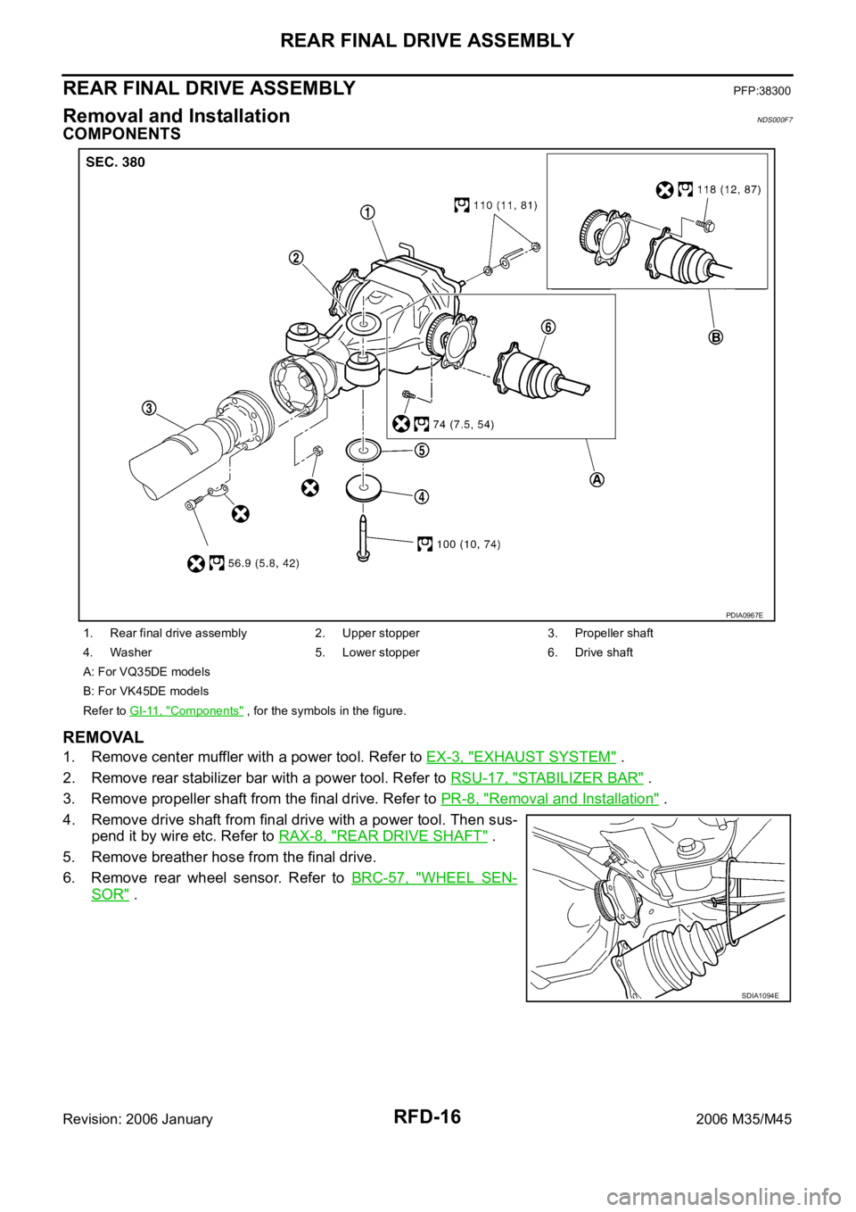
COMPONENTS
REMOVAL
1. Remove center muffler with a power tool. Refer to EX-3, "EXHAUST SYSTEM" .
2. Remove rear stabilizer bar with a power tool. Refer to RSU-17, "
STABILIZER BAR" .
3. Remove propeller shaft from the final drive. Refer to PR-8, "
Removal and Installation" .
4. Remove drive shaft from final drive with a power tool. Then sus-
pend it by wire etc. Refer to RAX-8, "
REAR DRIVE SHAFT" .
5. Remove breather hose from the final drive.
6. Remove rear wheel sensor. Refer to BRC-57, "
WHEEL SEN-
SOR" .
1. Rear final drive assembly 2. Upper stopper 3. Propeller shaft
4. Washer 5. Lower stopper 6. Drive shaft
A: For VQ35DE models
B: For VK45DE models
Refer to GI-11, "
Components" , for the symbols in the figure.
PDIA0967E
SDIA1094E
Page 5060 of 5621
REAR FINAL DRIVE ASSEMBLY
RFD-17
C
E
F
G
H
I
J
K
L
MA
B
RFD
Revision: 2006 January2006 M35/M45
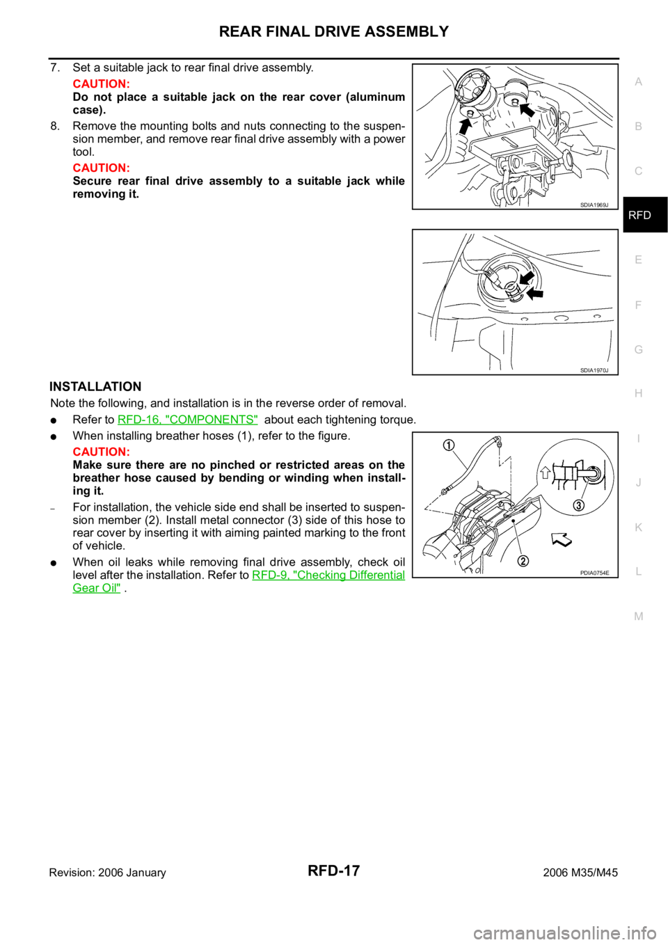
7. Set a suitable jack to rear final drive assembly.
CAUTION:
Do not place a suitable jack on the rear cover (aluminum
case).
8. Remove the mounting bolts and nuts connecting to the suspen-
sion member, and remove rear final drive assembly with a power
tool.
CAUTION:
Secure rear final drive assembly to a suitable jack while
removing it.
INSTALLATION
Note the following, and installation is in the reverse order of removal.
Refer to RFD-16, "COMPONENTS" about each tightening torque.
When installing breather hoses (1), refer to the figure.
CAUTION:
Make sure there are no pinched or restricted areas on the
breather hose caused by bending or winding when install-
ing it.
–For installation, the vehicle side end shall be inserted to suspen-
sion member (2). Install metal connector (3) side of this hose to
rear cover by inserting it with aiming painted marking to the front
of vehicle.
When oil leaks while removing final drive assembly, check oil
level after the installation. Refer to RFD-9, "
Checking Differential
Gear Oil" .
SDIA1969J
SDIA1970J
PDIA0754E
Page 5065 of 5621
RFD-22
REAR FINAL DRIVE ASSEMBLY
Revision: 2006 January2006 M35/M45
Companion Flange Runout
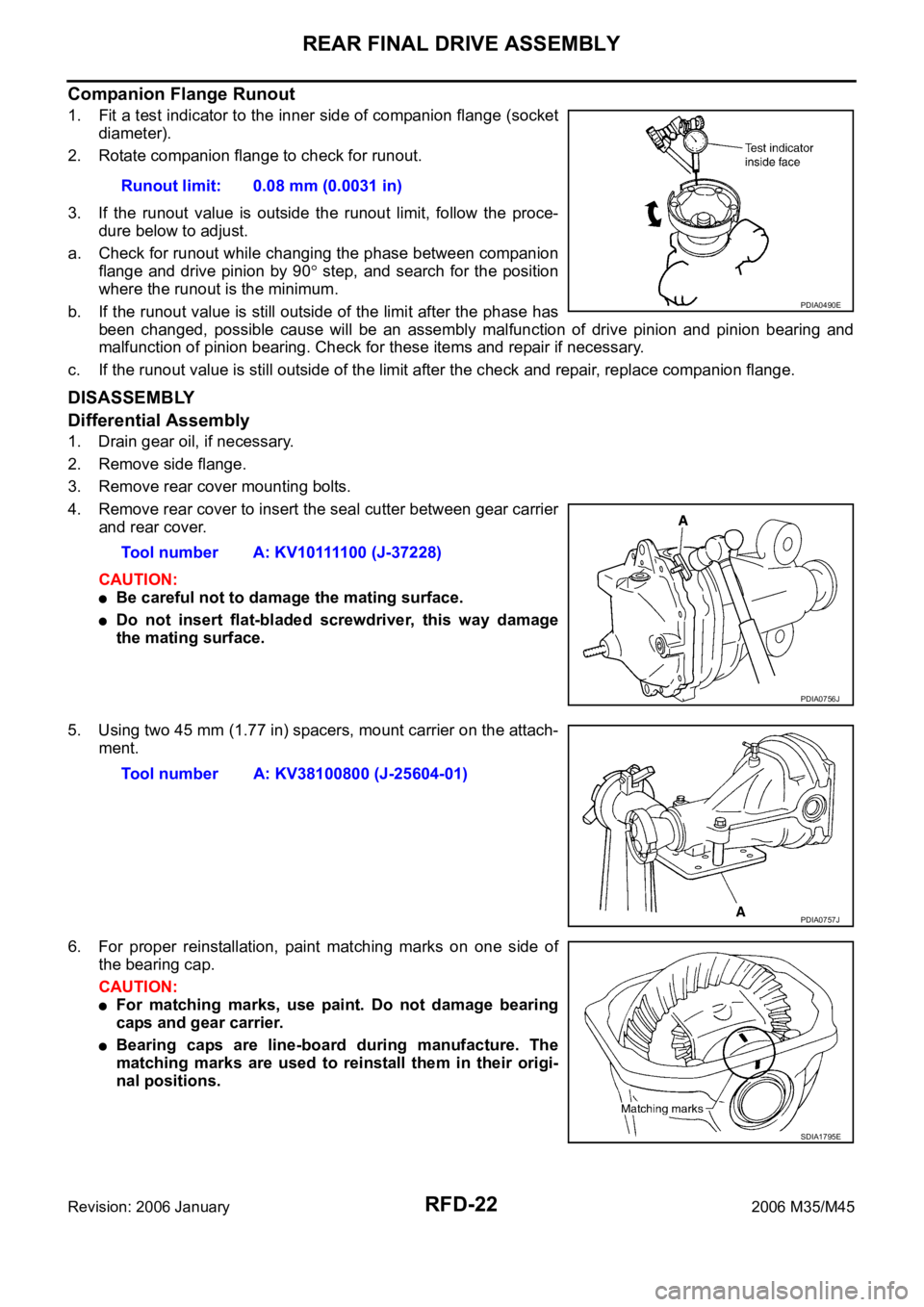
1. Fit a test indicator to the inner side of companion flange (socket
diameter).
2. Rotate companion flange to check for runout.
3. If the runout value is outside the runout limit, follow the proce-
dure below to adjust.
a. Check for runout while changing the phase between companion
flange and drive pinion by 90
step, and search for the position
where the runout is the minimum.
b. If the runout value is still outside of the limit after the phase has
been changed, possible cause will be an assembly malfunction of drive pinion and pinion bearing and
malfunction of pinion bearing. Check for these items and repair if necessary.
c. If the runout value is still outside of the limit after the check and repair, replace companion flange.
DISASSEMBLY
Differential Assembly
1. Drain gear oil, if necessary.
2. Remove side flange.
3. Remove rear cover mounting bolts.
4. Remove rear cover to insert the seal cutter between gear carrier
and rear cover.
CAUTION:
Be careful not to damage the mating surface.
Do not insert flat-bladed screwdriver, this way damage
the mating surface.
5. Using two 45 mm (1.77 in) spacers, mount carrier on the attach-
ment.
6. For proper reinstallation, paint matching marks on one side of
the bearing cap.
CAUTION:
For matching marks, use paint. Do not damage bearing
caps and gear carrier.
Bearing caps are line-board during manufacture. The
matching marks are used to reinstall them in their origi-
nal positions.Runout limit: 0.08 mm (0.0031 in)
PDIA0490E
Tool number A: KV10111100 (J-37228)
PDIA0756J
Tool number A: KV38100800 (J-25604-01)
PDIA0757J
SDIA1795E
Page 5067 of 5621

RFD-24
REAR FINAL DRIVE ASSEMBLY
Revision: 2006 January2006 M35/M45
10. For proper reinstallation, paint matching marks on one differen-
tial case assembly.
CAUTION:
For matching marks, use paint. Do not damage differential
case and drive gear.
11. Remove drive gear mounting bolts.
12. Tap drive gear off differential case assembly with a soft hammer.
CAUTION:
Tap evenly all around to keep drive gear from bending.
13. Remove lock pin of pinion mate shaft with a punch from drive
gear side.
14. Remove pinion mate shaft.
15. Turn pinion mate gear, then remove pinion mate gear, pinion
mate thrust washer, side gear and side gear thrust washer from
differential case.
Drive Pinion Assembly
1. Remove differential assembly. Refer to RFD-22, "Differential Assembly" .
PDIA0496E
PDIA0759J
SDIA0031J
SDIA0032J
Page 5070 of 5621
REAR FINAL DRIVE ASSEMBLY
RFD-27
C
E
F
G
H
I
J
K
L
MA
B
RFD
Revision: 2006 January2006 M35/M45
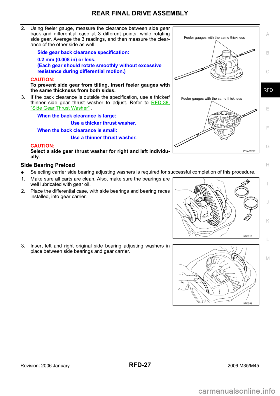
2. Using feeler gauge, measure the clearance between side gear
back and differential case at 3 different points, while rotating
side gear. Average the 3 readings, and then measure the clear-
ance of the other side as well.
CAUTION:
To prevent side gear from tilting, insert feeler gauges with
the same thickness from both sides.
3. If the back clearance is outside the specification, use a thicker/
thinner side gear thrust washer to adjust. Refer to RFD-38,
"Side Gear Thrust Washer" .
CAUTION:
Select a side gear thrust washer for right and left individu-
ally.
Side Bearing Preload
Selecting carrier side bearing adjusting washers is required for successful completion of this procedure.
1. Make sure all parts are clean. Also, make sure the bearings are
well lubricated with gear oil.
2. Place the differential case, with side bearings and bearing races
installed, into gear carrier.
3. Insert left and right original side bearing adjusting washers in
place between side bearings and gear carrier.Side gear back clearance specification:
0.2 mm (0.008 in) or less.
(Each gear should rotate smoothly without excessive
resistance during differential motion.)
When the back clearance is large:
Use a thicker thrust washer.
When the back clearance is small:
Use a thinner thrust washer.
PDIA0576E
SPD527
SPD558
Page 5071 of 5621

RFD-28
REAR FINAL DRIVE ASSEMBLY
Revision: 2006 January2006 M35/M45
4. Install bearing caps in their correct locations and tighten bearing
cap mounting bolts to the specified torque. Refer to RFD-18,
"COMPONENTS" .
5. Turn the carrier several times to seat the bearings.
6. Measure the turning torque of the carrier at the drive gear
mounting bolts with a spring gauge.
7. If the turning torque is outside the specification, use a thicker/
thinner side bearing adjusting washer to adjust. Refer to RFD-
38, "Side Bearing Adjusting Washer" .
CAUTION:
Select a side bearing adjusting washer for right and left
individually.
8. Record the total amount of washer thickness required for the correct carrier side bearing preload.
Pinion Gear Height
1. Make sure all parts are clean and that the bearings are well
lubricated.
2. Assemble the pinion gear bearings into the differential shim
selector tool.
SDIA1795E
Tool number : — (J-8129)
Specification:
34.2 - 39.2 N (3.5 - 4.0 kg, 7.7 - 8.8 lb) of pulling force at
the drive gear bolt
SPD194A
If the turning torque is less than the specified range:
Use a thicker thrust washer.
If the turning torque is greater than the specification:
Use a thinner thrust washer.
SPD772
Tool number : — (J-34309)
SPD769
Page 5072 of 5621
REAR FINAL DRIVE ASSEMBLY
RFD-29
C
E
F
G
H
I
J
K
L
MA
B
RFD
Revision: 2006 January2006 M35/M45
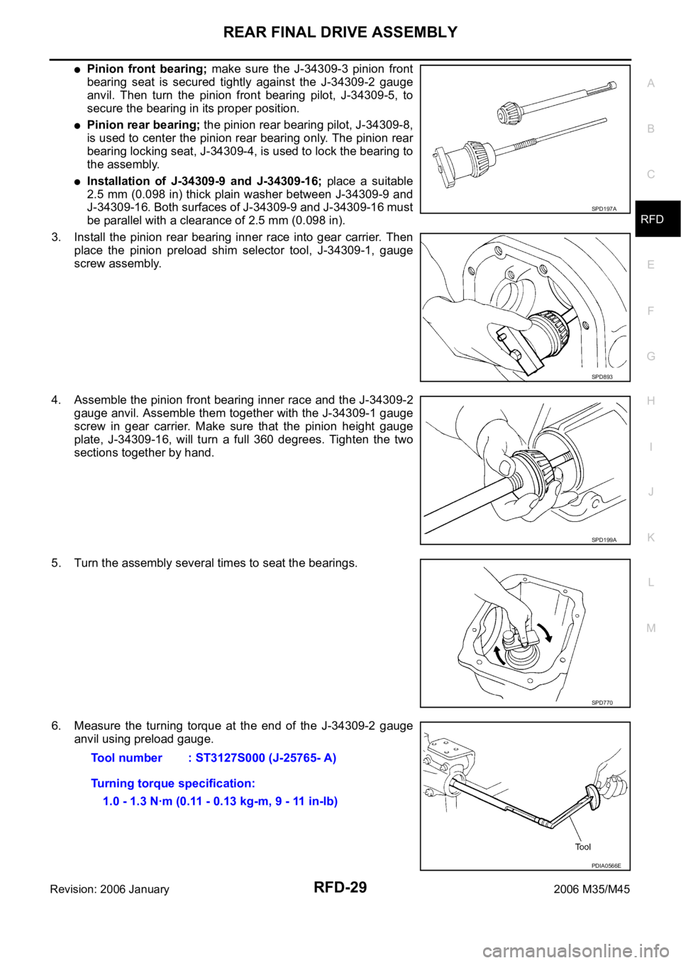
Pinion front bearing; make sure the J-34309-3 pinion front
bearing seat is secured tightly against the J-34309-2 gauge
anvil. Then turn the pinion front bearing pilot, J-34309-5, to
secure the bearing in its proper position.
Pinion rear bearing; the pinion rear bearing pilot, J-34309-8,
is used to center the pinion rear bearing only. The pinion rear
bearing locking seat, J-34309-4, is used to lock the bearing to
the assembly.
Installation of J-34309-9 and J-34309-16; place a suitable
2.5 mm (0.098 in) thick plain washer between J-34309-9 and
J-34309-16. Both surfaces of J-34309-9 and J-34309-16 must
be parallel with a clearance of 2.5 mm (0.098 in).
3. Install the pinion rear bearing inner race into gear carrier. Then
place the pinion preload shim selector tool, J-34309-1, gauge
screw assembly.
4. Assemble the pinion front bearing inner race and the J-34309-2
gauge anvil. Assemble them together with the J-34309-1 gauge
screw in gear carrier. Make sure that the pinion height gauge
plate, J-34309-16, will turn a full 360 degrees. Tighten the two
sections together by hand.
5. Turn the assembly several times to seat the bearings.
6. Measure the turning torque at the end of the J-34309-2 gauge
anvil using preload gauge.
SPD197A
SPD893
SPD199A
SPD770
Tool number : ST3127S000 (J-25765- A)
Turning torque specification:
1.0 - 1.3 Nꞏm (0.11 - 0.13 kg-m, 9 - 11 in-lb)
PDIA0566E
Page 5073 of 5621
RFD-30
REAR FINAL DRIVE ASSEMBLY
Revision: 2006 January2006 M35/M45
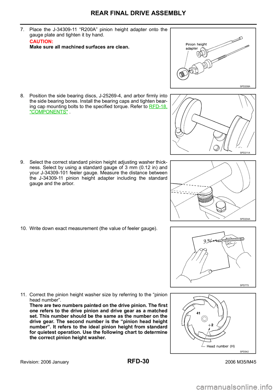
7. Place the J-34309-11 “R200A” pinion height adapter onto the
gauge plate and tighten it by hand.
CAUTION:
Make sure all machined surfaces are clean.
8. Position the side bearing discs, J-25269-4, and arbor firmly into
the side bearing bores. Install the bearing caps and tighten bear-
ing cap mounting bolts to the specified torque. Refer to RFD-18,
"COMPONENTS" .
9. Select the correct standard pinion height adjusting washer thick-
ness. Select by using a standard gauge of 3 mm (0.12 in) and
your J-34309-101 feeler gauge. Measure the distance between
the J-34309-11 pinion height adapter including the standard
gauge and the arbor.
10. Write down exact measurement (the value of feeler gauge).
11. Correct the pinion height washer size by referring to the “pinion
head number”.
There are two numbers painted on the drive pinion. The first
one refers to the drive pinion and drive gear as a matched
set. This number should be the same as the number on the
drive gear. The second number is the “pinion head height
number”. It refers to the ideal pinion height from standard
for quietest operation. Use the following chart to determine
the correct pinion height washer.
SPD208A
SPD211A
SPD204A
SPD775
SPD542
Page 5074 of 5621

REAR FINAL DRIVE ASSEMBLY
RFD-31
C
E
F
G
H
I
J
K
L
MA
B
RFD
Revision: 2006 January2006 M35/M45
12. Select the correct pinion height adjusting washer. Refer to RFD-38, "Pinion Height Adjusting Washer" .
13. Remove the J-34309 differential shim selector tool from the final
drive housing. Then disassemble to retrieve the pinion bearings.
ASSEMBLY
Drive Pinion Assembly
1. Install front bearing outer race (1) and rear bearing outer race
(2) using drifts.
CAUTION:
At first, using a hammer, tap bearing outer race until it
becomes flat to gear carrier.
Do not reuse pinion front and rear bearing outer race.
2. Select drive pinion height adjusting washer. Refer to RFD-28,
"Pinion Gear Height" .
Pinion head height numberAdd or remove from the standard pinion height
adjusting washer thickness measurement
- 6
- 5
- 4
- 3
- 2
- 1
0
+1
+2
+3
+4
+5
+6Add 0.06 mm (0.0024 in)
Add 0.05 mm (0.0020 in)
Add 0.04 mm (0.0016 in)
Add 0.03 mm (0.0012 in)
Add 0.02 mm (0.0008 in)
Add 0.01 mm (0.0004 in)
Use the selected washer thickness
Subtract 0.01 mm (0.0004 in)
Subtract 0.02 mm (0.0008 in)
Subtract 0.03 mm (0.0012 in)
Subtract 0.04 mm (0.0016 in)
Subtract 0.05 mm (0.0020 in)
Subtract 0.06 mm (0.0024 in)
SPD205A
Tool number A: ST30720000 (J-25405)
B: KV40105230 ( — )
C: ST30611000 (J-25742-1)
D: ST30613000 (J-25742-3)
PDIA0761J
Page 5075 of 5621
RFD-32
REAR FINAL DRIVE ASSEMBLY
Revision: 2006 January2006 M35/M45
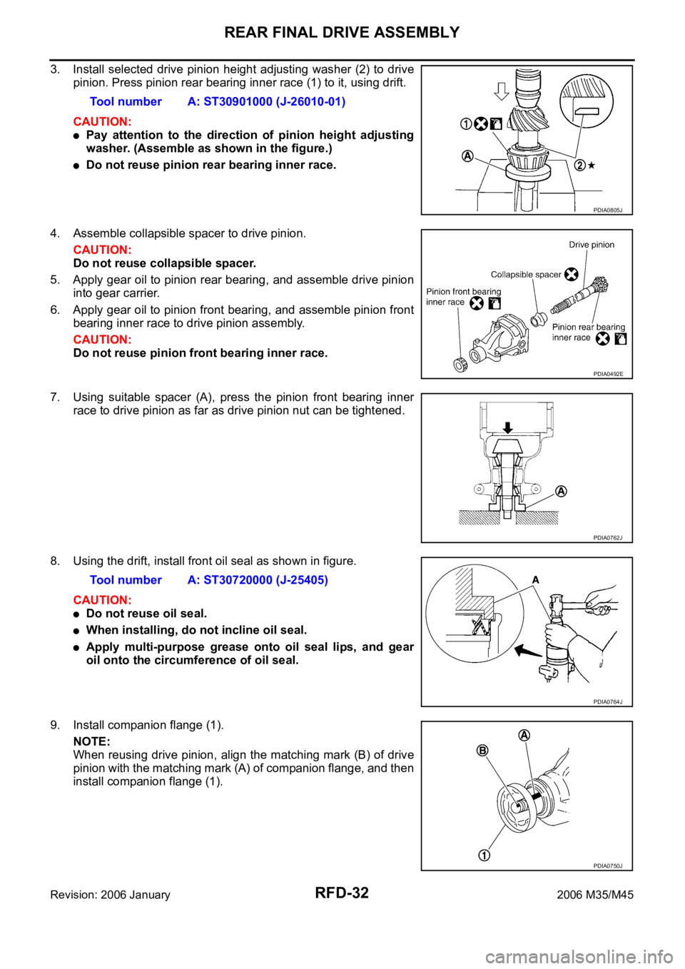
3. Install selected drive pinion height adjusting washer (2) to drive
pinion. Press pinion rear bearing inner race (1) to it, using drift.
CAUTION:
Pay attention to the direction of pinion height adjusting
washer. (Assemble as shown in the figure.)
Do not reuse pinion rear bearing inner race.
4. Assemble collapsible spacer to drive pinion.
CAUTION:
Do not reuse collapsible spacer.
5. Apply gear oil to pinion rear bearing, and assemble drive pinion
into gear carrier.
6. Apply gear oil to pinion front bearing, and assemble pinion front
bearing inner race to drive pinion assembly.
CAUTION:
Do not reuse pinion front bearing inner race.
7. Using suitable spacer (A), press the pinion front bearing inner
race to drive pinion as far as drive pinion nut can be tightened.
8. Using the drift, install front oil seal as shown in figure.
CAUTION:
Do not reuse oil seal.
When installing, do not incline oil seal.
Apply multi-purpose grease onto oil seal lips, and gear
oil onto the circumference of oil seal.
9. Install companion flange (1).
NOTE:
When reusing drive pinion, align the matching mark (B) of drive
pinion with the matching mark (A) of companion flange, and then
install companion flange (1).Tool number A: ST30901000 (J-26010-01)
PDIA0805J
PDIA0492E
PDIA0762J
Tool number A: ST30720000 (J-25405)
PDIA0764J
PDIA0750J