check INFINITI M35 2006 Factory Service Manual
[x] Cancel search | Manufacturer: INFINITI, Model Year: 2006, Model line: M35, Model: INFINITI M35 2006Pages: 5621, PDF Size: 65.56 MB
Page 344 of 5621

ON-VEHICLE SERVICE
AT-265
D
E
F
G
H
I
J
K
L
MA
B
AT
Revision: 2006 January2006 M35/M45
12. Straighten terminal clip to free revolution sensor harness.
13. Remove revolution sensor from transmission case.
CAUTION:
Do not subject it to impact by dropping or hitting it.
Do not disassemble.
Do not allow metal filings, etc., to get on the sensor's
front edge magnetic area.
Do not place in an area affected by magnetism.
Installation
CAUTION:
After completing installation, check A/T fluid leakage, A/T fluid level and A/T position. Refer to AT- 1 3 ,
"Checking A/T Fluid" , AT- 2 2 8 , "Checking of A/T Position" .
1. Install revolution sensor in transmission case. Tighten a neces-
sary bolt for revolution sensor with specified torque. Refer to AT-
261, "REMOVAL AND INSTALLATION" .
CAUTION:
Do not subject it to impact by dropping or hitting it.
Do not disassemble.
Do not allow metal filings, etc., to get on the sensor's
front edge magnetic area.
Do not place in an area affected by magnetism.
2. Connect revolution sensor connector.
SCIA7525E
SCIA3997E
SCIA3997E
SCIA7524E
Page 353 of 5621

AT-274
TRANSMISSION ASSEMBLY
Revision: 2006 January2006 M35/M45
INSPECTION
Installation and Inspection of Torque Converter
After inserting a torque converter to a A/T, be sure to check dis-
tance “A” to ensure it is within the reference value limit.
INSTALLATION
Install the removed parts in the reverse order of the removal, while paying attention to the following work.
When installing A/T assembly to the engine assembly, attach the fixing bolts in accordance with the follow-
ing standard.
VQ35DE models
VK45DE models
*: No.2 bolt also secures A/T fluid charging pipe.
Align the positions of tightening bolts for drive plate with those of
the torque converter, and temporarily tighten the bolts. Then,
tighten the bolts with the specified torque. Refer to AT- 2 7 1 ,
"COMPONENTS" .
CAUTION:
When turning crankshaft, turn it clockwise as viewed from
the front of the engine.
When tightening the tightening bolts for the torque con-
verter after fixing the crankshaft pulley bolts, be sure to
confirm the tightening torque of the crankshaft pulley
mounting bolts. Refer to EM-72, "
INSTALLATION" (for
VQ35DE engine), EM-208, "
INSTALLATION" (for VK45DE
engine).
After converter is installed to drive plate, rotate crankshaft several turns and check to be sure that
A/T rotates freely without binding.Distance “A”
VQ35DE models: 25.0 mm (0.98 in) or more
VK45DE models: 22.0 mm (0.87 in) or more
SCIA5694E
Bolt No. 1234
Number of bolts 1 5 2 2
Bolt length
“ ”mm (in)55 (2.17) 65 (2.56) 65 (2.56) 35 (1.38)
Tightening torque
Nꞏm (kg-m, ft-lb)75
(7.7, 55)55
(5.6, 41)47
(4.8, 35)
SCIA3949E
Bolt No. 1 2* 3
Number of bolts 5 1 4
Bolt length
“ ”mm (in)70 (2.76) 70 (2.76) 65 (2.56)
Tightening torque
Nꞏm (kg-m, ft-lb)11 3
(12, 83)74
(7.5, 55)
SCIA7068E
SCIA2288E
Page 354 of 5621
TRANSMISSION ASSEMBLY
AT-275
D
E
F
G
H
I
J
K
L
MA
B
AT
Revision: 2006 January2006 M35/M45
Install crankshaft position sensor (POS). Refer to EM-29, "Removal and Installation (2WD Models)" (for
VQ35DE engine), EM-187, "
Removal and Installation" (for VK45DE engine).
After completing installation, check A/T fluid leakage, A/T fluid level and A/T position. Refer to AT- 1 3 ,
"Checking A/T Fluid" , AT-228, "Checking of A/T Position" .
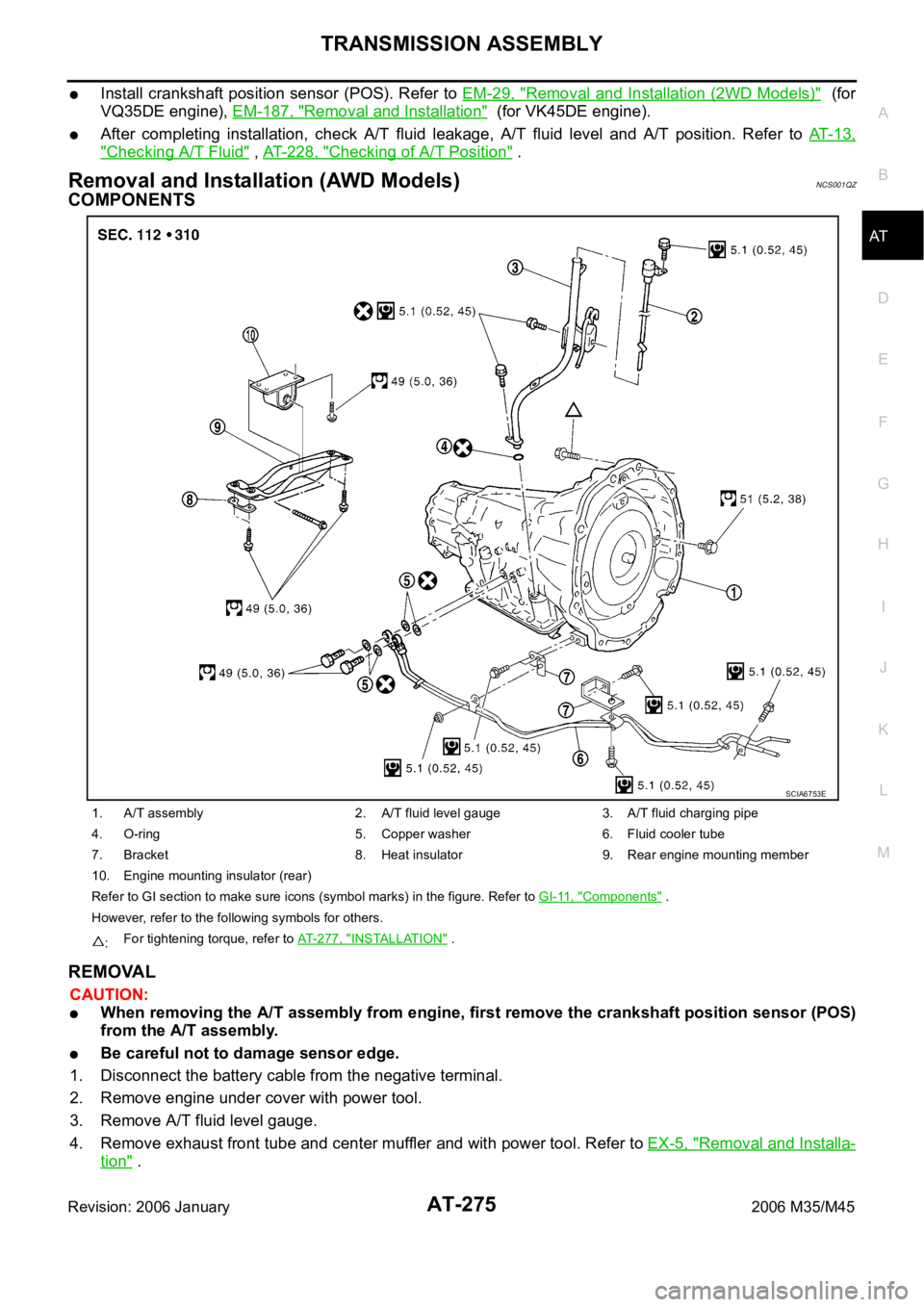
Removal and Installation (AWD Models) NCS001QZ
COMPONENTS
REMOVAL
CAUTION:
When removing the A/T assembly from engine, first remove the crankshaft position sensor (POS)
from the A/T assembly.
Be careful not to damage sensor edge.
1. Disconnect the battery cable from the negative terminal.
2. Remove engine under cover with power tool.
3. Remove A/T fluid level gauge.
4. Remove exhaust front tube and center muffler and with power tool. Refer to EX-5, "
Removal and Installa-
tion" .
1. A/T assembly 2. A/T fluid level gauge 3. A/T fluid charging pipe
4. O-ring 5. Copper washer 6. Fluid cooler tube
7. Bracket 8. Heat insulator 9. Rear engine mounting member
10. Engine mounting insulator (rear)
Refer to GI section to make sure icons (symbol marks) in the figure. Refer to GI-11, "
Components" .
However, refer to the following symbols for others.
:For tightening torque, refer to AT-277, "
INSTALLATION" .
SCIA6753E
Page 356 of 5621

TRANSMISSION ASSEMBLY
AT-277
D
E
F
G
H
I
J
K
L
MA
B
AT
Revision: 2006 January2006 M35/M45
INSPECTION
Installation and Inspection of Torque Converter
After inserting a torque converter to a A/T, be sure to check dis-
tance “A” to ensure it is within the reference value limit.
INSTALLATION
Install the removed parts in the reverse order of the removal, while paying attention to the following work.
When installing A/T assembly to the engine assembly, attach the
fixing bolts in accordance with the following standard.
Align the positions of tightening bolts for drive plate with those of
the torque converter, and temporarily tighten the bolts. Then,
tighten the bolts with the specified torque. Refer to AT- 2 7 5 ,
"COMPONENTS" .
CAUTION:
When turning crankshaft, turn it clockwise as viewed from
the front of the engine.
When tightening the tightening bolts for the torque con-
verter after fixing the crankshaft pulley bolts, be sure to
confirm the tightening torque of the crankshaft pulley
mounting bolts. Refer to EM-72, "
INSTALLATION" .
After converter is installed to drive plate, rotate crankshaft
several turns and check to be sure that A/T rotates freely without binding.
Install crankshaft position sensor (POS). Refer to EM-36, "Removal and Installation (AWD Models)" .
After completing installation, check A/T fluid leakage, A/T fluid level and A/T position. Refer to AT- 1 3 ,
"Checking A/T Fluid" , AT-228, "Checking of A/T Position" . Distance “A”: 25.0 mm (0.98 in) or more
SCIA5694E
Bolt No. 1 2 3 4
Number of bolts 1 5 2 1
Bolt length
“ ”mm (in)55 (2.17) 65 (2.56) 35 (1.38) 40 (1.57)
Tightening torque
Nꞏm (kg-m, ft-lb)75
(7.7, 55)47
(4.8, 35)34
(3.5, 25)
SCIA4600E
SCIA2288E
Page 377 of 5621

AT-298
DISASSEMBLY
Revision: 2006 January2006 M35/M45
DISASSEMBLYPFP:31020
DisassemblyNCS001R3
CAUTION:
Do not disassemble parts behind Drum Support. Refer to AT- 1 7 , "
Cross-Sectional View (VQ35DE Mod-
els for 2WD)" , AT- 1 8 , "Cross-Sectional View (VK45DE Models for 2WD)" , AT- 1 9 , "Cross-Sectional
View (AWD Models)" .
1. Drain ATF through drain plug.
2. Remove torque converter by holding it firmly and turing while
pulling straight out.
3. Check torque converter one-way clutch using a check tool as
shown at figure.
a. Insert a check tool into the groove of bearing support built into
one-way clutch outer race.
b. When fixing bearing support with a check tool, rotate one-way
clutch spline using a screwdriver.
c. Make sure that inner race rotates clockwise only. If not, replace
torque converter assembly.
4. Remove converter housing from transmission case.
CAUTION:
Be careful not to scratch converter housing.
SCIA5010E
SCIA3171E
SCIA4634E
Page 380 of 5621

DISASSEMBLY
AT-301
D
E
F
G
H
I
J
K
L
MA
B
AT
Revision: 2006 January2006 M35/M45
14. Loosen lock nut and remove band servo anchor end pin from
transmission case.
15. Remove brake band from transmission case.
To prevent brake linings from cracking or peeling, do not
stretch the flexible band unnecessarily. When removing
the brake band, always secure it with a clip as shown in
the figure at right.
Leave the clip in position after removing the brake band.
Check brake band facing for damage, cracks, wear or
burns.
16. Remove mid carrier assembly and rear carrier assembly as a
unit.
17. Remove mid carrier assembly from rear carrier assembly.
SCIA6512E
SCIA2580E
SAT655
SCIA5017E
SCIA5697E
Page 383 of 5621

AT-304
DISASSEMBLY
Revision: 2006 January2006 M35/M45
28. Remove oil pan and oil pan gasket.
29. Check foreign materials in oil pan to help determine causes of
malfunction. If the ATF is very dark, smells burned, or contains
foreign particles, the frictional material (clutches, band) may
need replacement. A tacky film that will not wipe clean indicates
varnish build up. Varnish can cause valves, servo, and clutches
to stick and can inhibit pump pressure.
If frictional material is detected, perform A/T fluid cooler
cleaning. Refer to AT- 1 4 , "
A/T Fluid Cooler Cleaning" .
30. Remove magnets from oil pan.
31. Disconnect A/T fluid temperature sensor 2 connector.
CAUTION:
Be careful not to damage connector.
32. Straighten terminal clips to free terminal cord assembly and A/T
fluid temperature sensor 2 harness.
SCIA2308E
SCIA5199E
SCIA5200E
SCIA5023E
SCIA5446E
Page 390 of 5621

DISASSEMBLY
AT-311
D
E
F
G
H
I
J
K
L
MA
B
AT
Revision: 2006 January2006 M35/M45
vii. Remove parking gear from output shaft.
viii. Remove seal rings from output shaft.
44. Remove needle bearing from transmission case.
45. Remove revolution sensor from transmission case.
CAUTION:
Do not subject it to impact by dropping or hitting it.
Do not disassemble.
Do not allow metal filings, etc., to get on the sensor's
front edge magnetic area.
Do not place in an area affected by magnetism.
46. Remove reverse brake snap ring (fixing plate) using 2 flat-
bladed screwdrivers.
NOTE:
Press out snap ring from the transmission case oil pan side gap
using a flat-bladed screwdriver, and remove it using a another
screwdriver.
47. Remove reverse brake retaining plate from transmission case.
Check facing for burns, cracks or damage. If necessary,
replace the plate.
SCIA5247E
SCIA5209E
SCIA5031E
SCIA2320E
SCIA5032E
Page 391 of 5621

AT-312
DISASSEMBLY
Revision: 2006 January2006 M35/M45
48. Remove N-spring from transmission case.
49. Remove reverse brake drive plates, driven plates and dish
plates from transmission case.
Check facing for burns, cracks or damage. If necessary,
replace the plate.
50. Remove snap ring (fixing spring retainer) using a flat-bladed
screwdriver.
51. Remove spring retainer and return spring from transmission
case.
52. Remove seal rings from drum support.
SCIA5214E
SCIA2322E
SCIA2323E
SCIA2324E
SCIA3333E
Page 401 of 5621

AT-322
REPAIR FOR COMPONENT PARTS
Revision: 2006 January2006 M35/M45
INSPECTION
3rd One-way Clutch
Check frictional surface for wear or damage.
CAUTION:
If necessary, replace the 3rd one-way clutch.
Front Sun Gear Snap Ring
Check for deformation, fatigue or damage.
CAUTION:
If necessary, replace the snap ring.
Front Sun Gear
Check for deformation, fatigue or damage.
CAUTION:
If necessary, replace the front sun gear.
ASSEMBLY
1. Install 3rd one-way clutch in front sun gear.
CAUTION:
Apply ATF to 3rd one-way clutch.
2. Using a flat-bladed screwdriver, install snap ring in front sun
gear.
3. Check operation of 3rd one-way clutch.
a. Hold oil pump assembly and turn front sun gear.
b. Check 3rd one-way clutch for correct locking and unlocking
directions.
CAUTION:
If not as shown in figure, check installation direction of 3rd
one-way clutch.
SCIA3111E
SCIA3110E
SCIA3131E