check INFINITI M35 2006 Factory Service Manual
[x] Cancel search | Manufacturer: INFINITI, Model Year: 2006, Model line: M35, Model: INFINITI M35 2006Pages: 5621, PDF Size: 65.56 MB
Page 451 of 5621

ATC-4Revision: 2006 January2006 M35/M45 and High-Pressure Pipe 2 ....................................162
REMOVAL ........................................................
.162
INSTALLATION ..................................................163
Removal and Installation of Liquid Tank ...............164
DISASSEMBLY AND ASSEMBLY ....................164
REMOVAL ........................................................
.164
INSTALLATION ..................................................165
Removal and Installation of Condenser ................165
REMOVAL ........................................................
.165
INSTALLATION ..................................................167
Removal and Installation of Refrigerant Pressure
Sensor ..................................................................167
REMOVAL ........................................................
.167
INSTALLATION ..................................................167
Removal and Installation of Evaporator ................168
REMOVAL ........................................................
.168
INSTALLATION ..................................................168Removal and Installation of Expansion Valve .......169
REMOVAL ..........................................................169
INSTALLATION ..................................................169
Checking for Refrigerant Leaks ............................170
Checking System for Leaks Using the Fluorescent
Leak Detector ........................................................170
Dye Injection .........................................................170
Electrical Refrigerant Leak Detector .....................171
PRECAUTIONS FOR HANDLING LEAK
DETECTOR .......................................................171
CHECKING PROCEDURE ................................172
SERVICE DATA AND SPECIFICATIONS (SDS) ....174
Compressor ..........................................................174
Lubricant ...............................................................174
Refrigerant ............................................................174
Engine Idling Speed ..............................................174
Belt Tension ..........................................................174
Page 452 of 5621

PRECAUTIONS
ATC-5
C
D
E
F
G
H
I
K
L
MA
B
AT C
Revision: 2006 January2006 M35/M45
PRECAUTIONSPFP:00001
Precautions for Supplemental Restraint System (SRS) “AIR BAG” and “SEAT
BELT PRE-TENSIONER”
NJS000FN
The Supplemental Restraint System such as “AIR BAG” and “SEAT BELT PRE-TENSIONER”, used along
with a front seat belt, helps to reduce the risk or severity of injury to the driver and front passenger for certain
types of collision. This system includes seat belt switch inputs and dual stage front air bag modules. The SRS
system uses the seat belt switches to determine the front air bag deployment, and may only deploy one front
air bag, depending on the severity of a collision and whether the front occupants are belted or unbelted.
Information necessary to service the system safely is included in the SRS and SB section of this Service Man-
ual.
WAR NING :
To avoid rendering the SRS inoperative, which could increase the risk of personal injury or death
in the event of a collision which would result in air bag inflation, all maintenance must be per-
formed by an authorized NISSAN/INFINITI dealer.
Improper maintenance, including incorrect removal and installation of the SRS, can lead to per-
sonal injury caused by unintentional activation of the system. For removal of Spiral Cable and Air
Bag Module, see the SRS section.
Do not use electrical test equipment on any circuit related to the SRS unless instructed to in this
Service Manual. SRS wiring harnesses can be identified by yellow and/or orange harnesses or
harness connectors.
Precautions Necessary for Steering Wheel Rotation After Battery DisconnectNJS000FO
NOTE:
This Procedure is applied only to models with Intelligent Key system and NVIS/IVIS (NISSAN/INFINITI
VEHICLE IMMOBILIZER SYSTEM - NATS).
Remove and install all control units after disconnecting both battery cables with the ignition knob in the
LOCK position.
Always use CONSULT-II to perform self-diagnosis as a part of each function inspection after finishing
work. If DTC is detected, perform trouble diagnosis according to self-diagnostic results.
For models equipped with the Intelligent Key system and NVIS/IVIS, an electrically controlled steering lock
mechanism is adopted on the key cylinder.
For this reason, if the battery is disconnected or if the battery is discharged, the steering wheel will lock and
steering wheel rotation will become impossible.
If steering wheel rotation is required when battery power is interrupted, follow the procedure below before
starting the repair operation.
OPERATION PROCEDURE
1. Connect both battery cables.
NOTE:
Supply power using jumper cables if battery is discharged.
2. Use the Intelligent Key or mechanical key to turn the ignition switch to the
ACC position. At this time, the
steering lock will be released.
3. Disconnect both battery cables. The steering lock will remain released and the steering wheel can be
rotated.
4. Perform the necessary repair operation.
5. When the repair work is completed, return the ignition switch to the
LOCK position before connecting
the battery cables. (At this time, the steering lock mechanism will engage.)
6. Perform a self-diagnosis check of all control units using CONSULT-II.
Page 455 of 5621
ATC-8
PRECAUTIONS
Revision: 2006 January2006 M35/M45
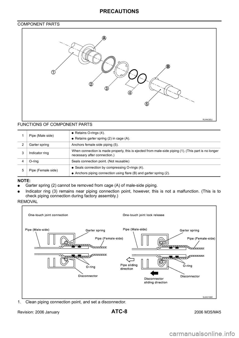
COMPONENT PARTS
FUNCTIONS OF COMPONENT PARTS
NOTE:
Garter spring (2) cannot be removed from cage (A) of male-side piping.
Indicator ring (3) remains near piping connection point, however, this is not a malfunction. (This is to
check piping connection during factory assembly.)
REMOVAL
1. Clean piping connection point, and set a disconnector.
1 Pipe (Male side)Retains O-rings (4).
Retains garter spring (2) in cage (A).
2 Garter spring Anchors female side piping (5).
3 Indicator ringWhen connection is made properly, this is ejected from male-side piping (1). (This part is no longer
necessary after connection.)
4 O-ring Seals connection point. (Not reusable)
5 Pipe (Female side)
Seals connection by compressing O-rings (4).
Anchors piping connection using flare (B) and garter spring (2).
RJIA4383J
SJIA0106E
Page 460 of 5621
PRECAUTIONS
ATC-13
C
D
E
F
G
H
I
K
L
MA
B
AT C
Revision: 2006 January2006 M35/M45
After compressor service operation, turn the compressor shaft by hand more than five turns in
both directions. This will equally distribute lubricant inside the compressor. After the compressor
is installed, let the engine idle and operate the compressor for one hour.
After replacing the compressor magnet clutch, apply voltage to the new one and check for normal
operation.
Precautions for Service EquipmentNJS000FU
RECOVERY/RECYCLING EQUIPMENT
Be certain to follow the manufacturer’s instructions for machine operation and machine maintenance. Never
introduce any refrigerant other than that specified into the machine.
ELECTRICAL LEAK DETECTOR
Be certain to follow the manufacturer’s instructions for tester operation and tester maintenance.
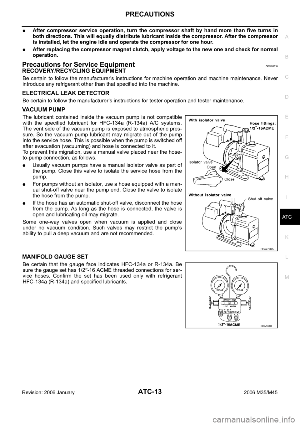
VACUUM PUMP
The lubricant contained inside the vacuum pump is not compatible
with the specified lubricant for HFC-134a (R-134a) A/C systems.
The vent side of the vacuum pump is exposed to atmospheric pres-
sure. So the vacuum pump lubricant may migrate out of the pump
into the service hose. This is possible when the pump is switched off
after evacuation (vacuuming) and hose is connected to it.
To prevent this migration, use a manual valve placed near the hose-
to-pump connection, as follows.
Usually vacuum pumps have a manual isolator valve as part of
the pump. Close this valve to isolate the service hose from the
pump.
For pumps without an isolator, use a hose equipped with a man-
ual shut-off valve near the pump end. Close the valve to isolate
the hose from the pump.
If the hose has an automatic shut-off valve, disconnect the hose
from the pump. As long as the hose is connected, the valve is
open and lubricating oil may migrate.
Some one-way valves open when vacuum is applied and close
under no vacuum condition. Such valves may restrict the pump’s
ability to pull a deep vacuum and are not recommended.
MANIFOLD GAUGE SET
Be certain that the gauge face indicates HFC-134a or R-134a. Be
sure the gauge set has 1/2
-16 ACME threaded connections for ser-
vice hoses. Confirm the set has been used only with refrigerant
HFC-134a (R-134a) and specified lubricants.
RHA270DA
SHA533D
Page 465 of 5621
ATC-18
PREPARATION
Revision: 2006 January2006 M35/M45
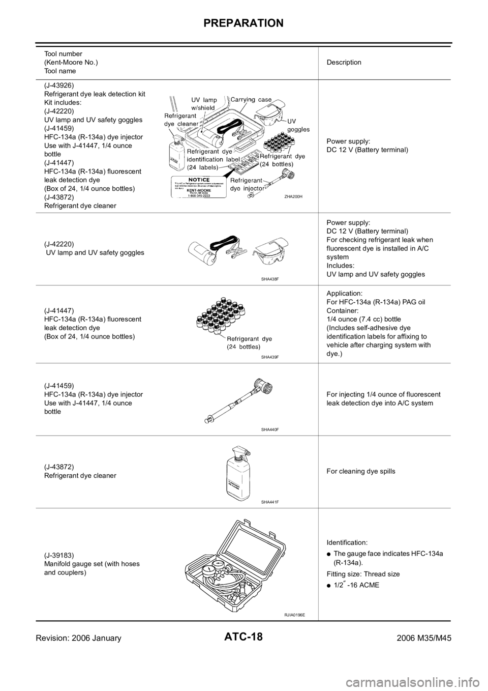
(J-43926)
Refrigerant dye leak detection kit
Kit includes:
(J-42220)
UV lamp and UV safety goggles
(J-41459)
HFC-134a (R-134a) dye injector
Use with J-41447, 1/4 ounce
bottle
(J-41447)
HFC-134a (R-134a) fluorescent
leak detection dye
(Box of 24, 1/4 ounce bottles)
(J-43872)
Refrigerant dye cleanerPower supply:
DC 12 V (Battery terminal)
(J-42220)
UV lamp and UV safety gogglesPower supply:
DC 12 V (Battery terminal)
For checking refrigerant leak when
fluorescent dye is installed in A/C
system
Includes:
UV lamp and UV safety goggles
(J-41447)
HFC-134a (R-134a) fluorescent
leak detection dye
(Box of 24, 1/4 ounce bottles)Application:
For HFC-134a (R-134a) PAG oil
Container:
1/4 ounce (7.4 cc) bottle
(Includes self-adhesive dye
identification labels for affixing to
vehicle after charging system with
dye.)
(J-41459)
HFC-134a (R-134a) dye injector
Use with J-41447, 1/4 ounce
bottleFor injecting 1/4 ounce of fluorescent
leak detection dye into A/C system
(J-43872)
Refrigerant dye cleanerFor cleaning dye spills
(J-39183)
Manifold gauge set (with hoses
and couplers)Identification:
The gauge face indicates HFC-134a
(R-134a).
Fitting size: Thread size
1/2 -16 ACME Tool number
(Kent-Moore No.)
Tool nameDescription
ZHA200H
SHA438F
SHA439F
SHA440F
SHA441F
RJIA0196E
Page 466 of 5621
PREPARATION
ATC-19
C
D
E
F
G
H
I
K
L
MA
B
AT C
Revision: 2006 January2006 M35/M45
Commercial Service ToolsNJS000FY
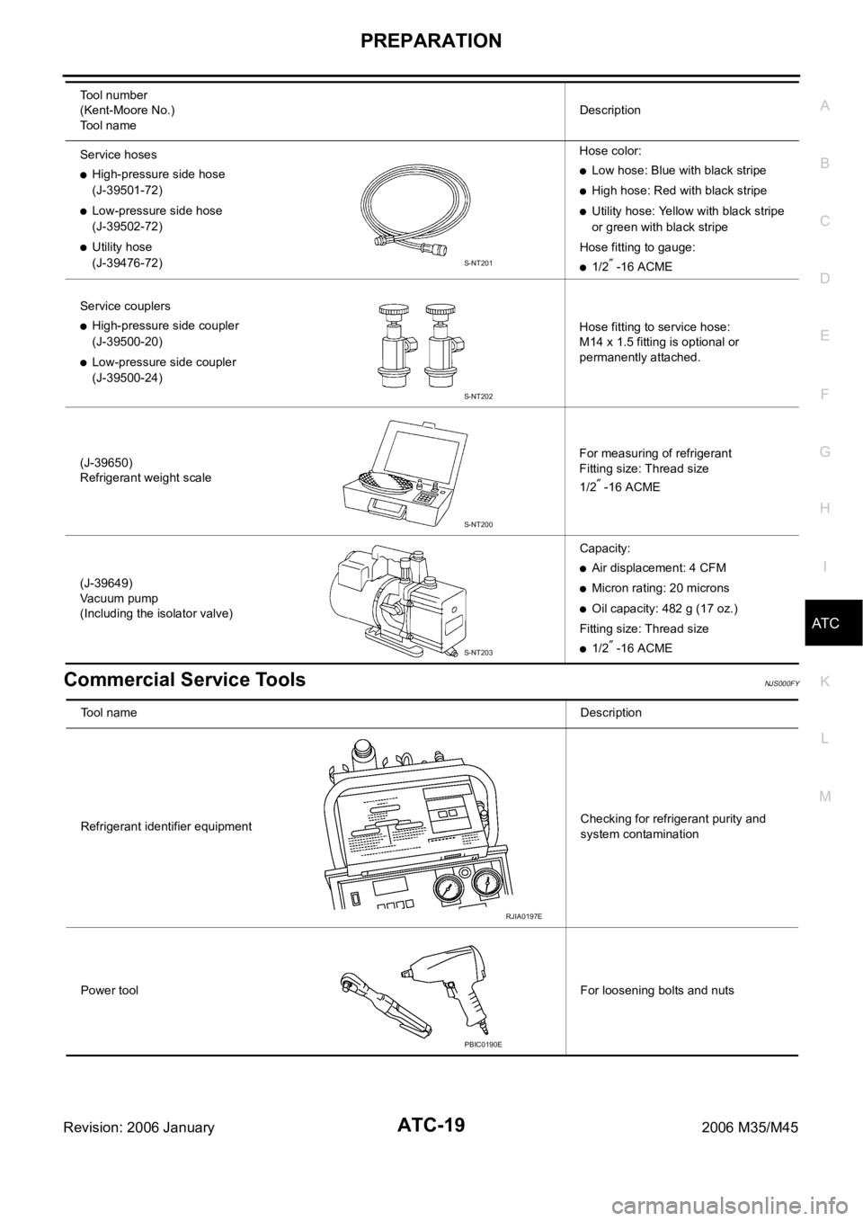
Service hoses
High-pressure side hose
(J-39501-72)
Low-pressure side hose
(J-39502-72)
Utility hose
(J-39476-72)Hose color:
Low hose: Blue with black stripe
High hose: Red with black stripe
Utility hose: Yellow with black stripe
or green with black stripe
Hose fitting to gauge:
1/2 -16 ACME
Service couplers
High-pressure side coupler
(J-39500-20)
Low-pressure side coupler
(J-39500-24)Hose fitting to service hose:
M14 x 1.5 fitting is optional or
permanently attached.
(J-39650)
Refrigerant weight scaleFor measuring of refrigerant
Fitting size: Thread size
1/2
-16 ACME
(J-39649)
Vacuum pump
(Including the isolator valve)Capacity:
Air displacement: 4 CFM
Micron rating: 20 microns
Oil capacity: 482 g (17 oz.)
Fitting size: Thread size
1/2 -16 ACME Tool number
(Kent-Moore No.)
Tool nameDescription
S-NT201
S-NT202
S-NT200
S-NT203
Tool nameDescription
Refrigerant identifier equipmentChecking for refrigerant purity and
system contamination
Power toolFor loosening bolts and nuts
RJIA0197E
PBIC0190E
Page 473 of 5621
ATC-26
LUBRICANT
Revision: 2006 January2006 M35/M45
LUBRICANTPFP:KLG00
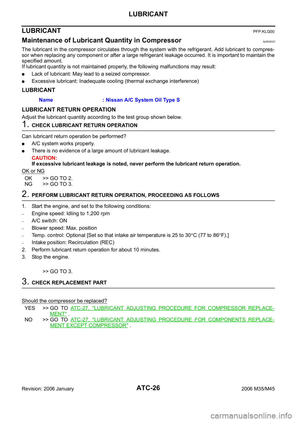
Maintenance of Lubricant Quantity in CompressorNJS000G3
The lubricant in the compressor circulates through the system with the refrigerant. Add lubricant to compres-
sor when replacing any component or after a large refrigerant leakage occurred. It is important to maintain the
specified amount.
If lubricant quantity is not maintained properly, the following malfunctions may result:
Lack of lubricant: May lead to a seized compressor.
Excessive lubricant: Inadequate cooling (thermal exchange interference)
LUBRICANT
LUBRICANT RETURN OPERATION
Adjust the lubricant quantity according to the test group shown below.
1. CHECK LUBRICANT RETURN OPERATION
Can lubricant return operation be performed?
A/C system works properly.
There is no evidence of a large amount of lubricant leakage.
CAUTION:
If excessive lubricant leakage is noted, never perform the lubricant return operation.
OK or NG
OK >> GO TO 2.
NG >> GO TO 3.
2. PERFORM LUBRICANT RETURN OPERATION, PROCEEDING AS FOLLOWS
1. Start the engine, and set to the following conditions:
–Engine speed: Idling to 1,200 rpm
–A/C switch: ON
–Blower speed: Max. position
–Temp. control: Optional [Set so that intake air temperature is 25 to 30C (77 to 86F).]
–Intake position: Recirculation (REC)
2. Perform lubricant return operation for about 10 minutes.
3. Stop the engine.
>> GO TO 3.
3. CHECK REPLACEMENT PART
Should the compressor be replaced?
YES >> GO TO AT C - 2 7 , "LUBRICANT ADJUSTING PROCEDURE FOR COMPRESSOR REPLACE-
MENT" .
NO >> GO TO AT C - 2 7 , "
LUBRICANT ADJUSTING PROCEDURE FOR COMPONENTS REPLACE-
MENT EXCEPT COMPRESSOR" . Name : Nissan A/C System Oil Type S
Page 474 of 5621
LUBRICANT
ATC-27
C
D
E
F
G
H
I
K
L
MA
B
AT C
Revision: 2006 January2006 M35/M45
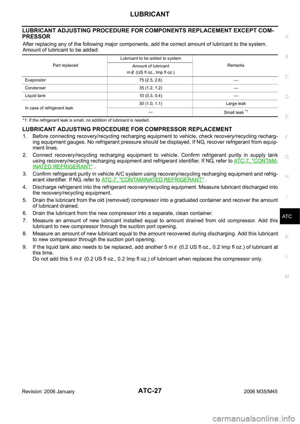
LUBRICANT ADJUSTING PROCEDURE FOR COMPONENTS REPLACEMENT EXCEPT COM-
PRESSOR
After replacing any of the following major components, add the correct amount of lubricant to the system.
Amount of lubricant to be added:
*1: If the refrigerant leak is small, no addition of lubricant is needed.
LUBRICANT ADJUSTING PROCEDURE FOR COMPRESSOR REPLACEMENT
1. Before connecting recovery/recycling recharging equipment to vehicle, check recovery/recycling recharg-
ing equipment gauges. No refrigerant pressure should be displayed. If NG, recover refrigerant from equip-
ment lines.
2. Connect recovery/recycling recharging equipment to vehicle. Confirm refrigerant purity in supply tank
using recovery/recycling recharging equipment and refrigerant identifier. If NG, refer to ATC-7, "
CONTAM-
INATED REFRIGERANT" .
3. Confirm refrigerant purity in vehicle A/C system using recovery/recycling recharging equipment and refrig-
erant identifier. If NG, refer to ATC-7, "
CONTAMINATED REFRIGERANT" .
4. Discharge refrigerant into the refrigerant recovery/recycling equipment. Measure lubricant discharged into
the recovery/recycling equipment.
5. Drain the lubricant from the old (removed) compressor into a graduated container and recover the amount
of lubricant drained.
6. Drain the lubricant from the new compressor into a separate, clean container.
7. Measure an amount of new lubricant installed equal to amount drained from old compressor. Add this
lubricant to new compressor through the suction port opening.
8. Measure an amount of new lubricant equal to the amount recovered during discharging. Add this lubricant
to new compressor through the suction port opening.
9. If the liquid tank also needs to be replaced, add another 5 m (0.2 US fl oz., 0.2 Imp fl oz.) of lubricant at
this time.
Do not add this 5 m (0.2 US fl oz., 0.2 Imp fl oz.) of lubricant when replaces the compressor only.
Part replacedLubricant to be added to system
Remarks
Amount of lubricant
m (US fl oz., Imp fl oz.)
Evaporator 75 (2.5, 2.6) —
Condenser 35 (1.2, 1.2) —
Liquid tank 10 (0.3, 0.4) —
In case of refrigerant leak30 (1.0, 1.1) Large leak
—
Small leak
*1
Page 476 of 5621
AIR CONDITIONER CONTROL
ATC-29
C
D
E
F
G
H
I
K
L
MA
B
AT C
Revision: 2006 January2006 M35/M45
AIR CONDITIONER CONTROLPFP:27500
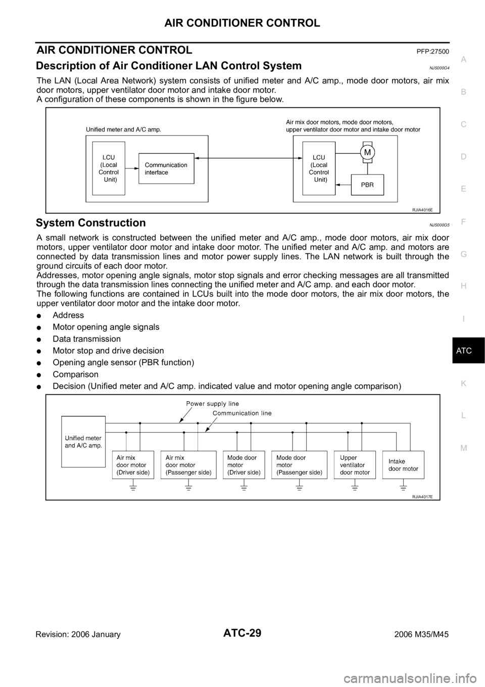
Description of Air Conditioner LAN Control SystemNJS000G4
The LAN (Local Area Network) system consists of unified meter and A/C amp., mode door motors, air mix
door motors, upper ventilator door motor and intake door motor.
A configuration of these components is shown in the figure below.
System ConstructionNJS000G5
A small network is constructed between the unified meter and A/C amp., mode door motors, air mix door
motors, upper ventilator door motor and intake door motor. The unified meter and A/C amp. and motors are
connected by data transmission lines and motor power supply lines. The LAN network is built through the
ground circuits of each door motor.
Addresses, motor opening angle signals, motor stop signals and error checking messages are all transmitted
through the data transmission lines connecting the unified meter and A/C amp. and each door motor.
The following functions are contained in LCUs built into the mode door motors, the air mix door motors, the
upper ventilator door motor and the intake door motor.
Address
Motor opening angle signals
Data transmission
Motor stop and drive decision
Opening angle sensor (PBR function)
Comparison
Decision (Unified meter and A/C amp. indicated value and motor opening angle comparison)
RJIA4016E
RJIA4017E
Page 477 of 5621
ATC-30
AIR CONDITIONER CONTROL
Revision: 2006 January2006 M35/M45
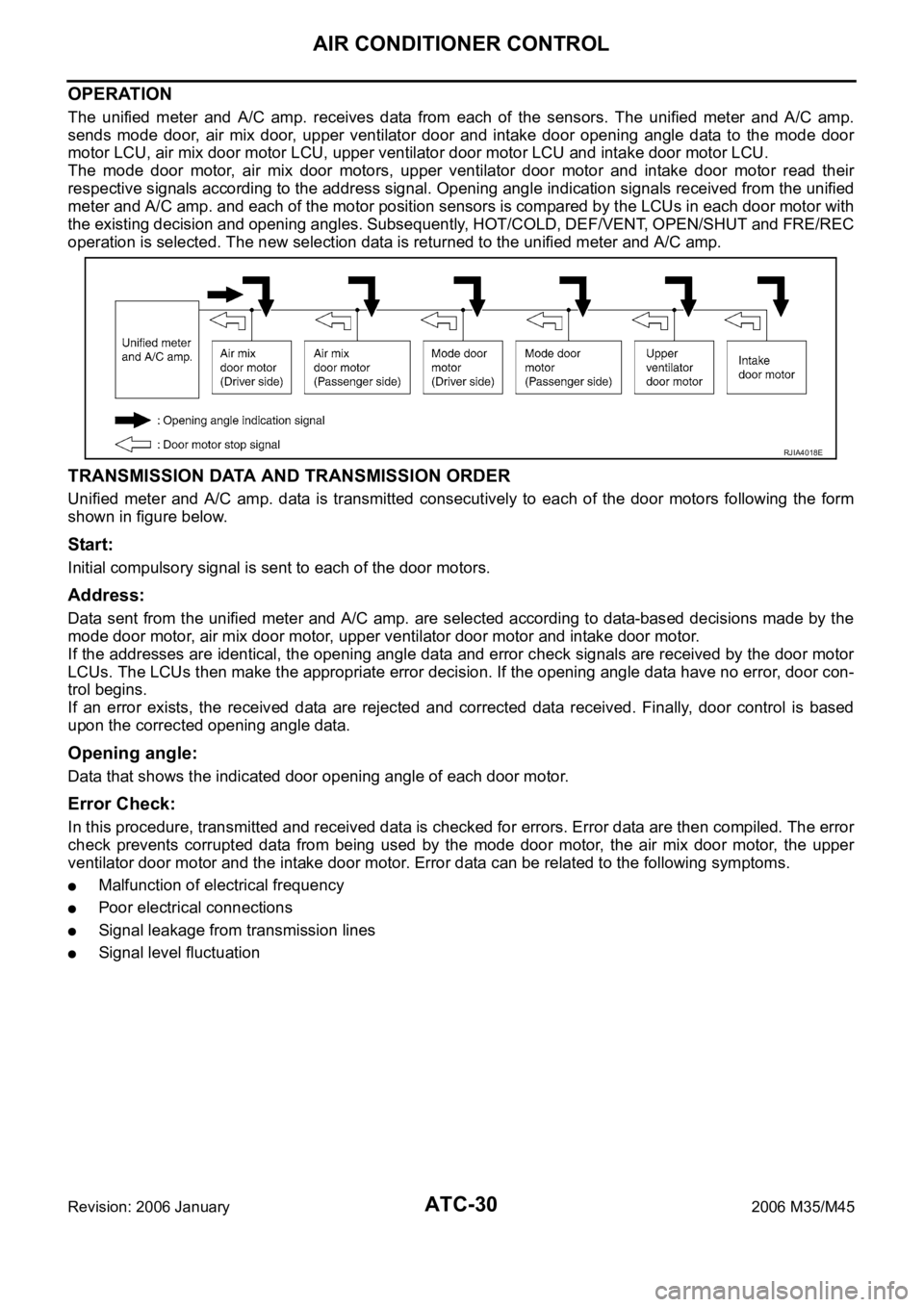
OPERATION
The unified meter and A/C amp. receives data from each of the sensors. The unified meter and A/C amp.
sends mode door, air mix door, upper ventilator door and intake door opening angle data to the mode door
motor LCU, air mix door motor LCU, upper ventilator door motor LCU and intake door motor LCU.
The mode door motor, air mix door motors, upper ventilator door motor and intake door motor read their
respective signals according to the address signal. Opening angle indication signals received from the unified
meter and A/C amp. and each of the motor position sensors is compared by the LCUs in each door motor with
the existing decision and opening angles. Subsequently, HOT/COLD, DEF/VENT, OPEN/SHUT and FRE/REC
operation is selected. The new selection data is returned to the unified meter and A/C amp.
TRANSMISSION DATA AND TRANSMISSION ORDER
Unified meter and A/C amp. data is transmitted consecutively to each of the door motors following the form
shown in figure below.
Start:
Initial compulsory signal is sent to each of the door motors.
Address:
Data sent from the unified meter and A/C amp. are selected according to data-based decisions made by the
mode door motor, air mix door motor, upper ventilator door motor and intake door motor.
If the addresses are identical, the opening angle data and error check signals are received by the door motor
LCUs. The LCUs then make the appropriate error decision. If the opening angle data have no error, door con-
trol begins.
If an error exists, the received data are rejected and corrected data received. Finally, door control is based
upon the corrected opening angle data.
Opening angle:
Data that shows the indicated door opening angle of each door motor.
Error Check:
In this procedure, transmitted and received data is checked for errors. Error data are then compiled. The error
check prevents corrupted data from being used by the mode door motor, the air mix door motor, the upper
ventilator door motor and the intake door motor. Error data can be related to the following symptoms.
Malfunction of electrical frequency
Poor electrical connections
Signal leakage from transmission lines
Signal level fluctuation
RJIA4018E