door lock INFINITI M35 2006 Factory User Guide
[x] Cancel search | Manufacturer: INFINITI, Model Year: 2006, Model line: M35, Model: INFINITI M35 2006Pages: 5621, PDF Size: 65.56 MB
Page 950 of 5621

SQUEAK AND RATTLE TROUBLE DIAGNOSIS
BL-11
C
D
E
F
G
H
J
K
L
MA
B
BL
Revision: 2006 January2006 M35/M45
INSULATOR (Light foam block)
80845-71L00: 30 mm (1.18 in) thick, 30
50 mm (1.181.97 in)
FELT CLOTHTAPE
Used to insulate where movement does not occur. Ideal for instrument panel applications.
68370-4B000: 15
25 mm (0.590.98 in) pad/68239-13E00: 5 mm (0.20 in) wide tape roll
The following materials, not found in the kit, can also be used to repair squeaks and rattles.
UHMW (TEFLON) TAPE
Insulates where slight movement is present. Ideal for instrument panel applications.
SILICONE GREASE
Used in place of UHMW tape that will be visible or not fit. Will only last a few months.
SILICONE SPRAY
Use when grease cannot be applied.
DUCT TAPE
Use to eliminate movement.
CONFIRM THE REPAIR
Confirm that the cause of a noise is repaired by test driving the vehicle. Operate the vehicle under the same
conditions as when the noise originally occurred. Refer to the notes on the Diagnostic Worksheet.
Generic Squeak and Rattle TroubleshootingNIS001WH
Refer to Table of Contents for specific component removal and installation information.
INSTRUMENT PANEL
Most incidents are caused by contact and movement between:
1. The cluster lid A and instrument panel
2. Acrylic lens and combination meter housing
3. Instrument panel to front pillar garnish
4. Instrument panel to windshield
5. Instrument panel mounting pins
6. Wiring harnesses behind the combination meter
7. A/C defroster duct and duct joint
These incidents can usually be located by tapping or moving the components to duplicate the noise or by
pressing on the components while driving to stop the noise. Most of these incidents can be repaired by apply-
ing felt cloth tape or silicon spray (in hard to reach areas). Urethane pads can be used to insulate wiring har-
ness.
CAUTION:
Do not use silicone spray to isolate a squeak or rattle. If you saturate the area with silicone, you will
not be able to recheck the repair.
CENTER CONSOLE
Components to pay attention to include:
1. Shifter assembly cover to finisher
2. A/C control unit and cluster lid C
3. Wiring harnesses behind audio and A/C control unit
The instrument panel repair and isolation procedures also apply to the center console.
DOORS
Pay attention to the:
1. Finisher and inner panel making a slapping noise
2. Inside handle escutcheon to door finisher
3. Wiring harnesses tapping
4. Door striker out of alignment causing a popping noise on starts and stops
Tapping or moving the components or pressing on them while driving to duplicate the conditions can isolate
many of these incidents. You can usually insulate the areas with felt cloth tape or insulator foam blocks from
the Nissan Squeak and Rattle Kit (J-43980) to repair the noise.
Page 963 of 5621
BL-24
POWER DOOR LOCK SYSTEM
Revision: 2006 January2006 M35/M45
POWER DOOR LOCK SYSTEMPFP:24814
Component Parts and Harness Connector LocationNIS001WP
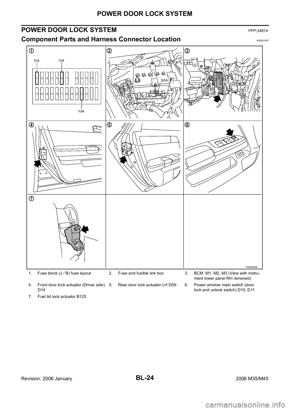
1. Fuse block (J / B) fuse layout 2. Fuse and fusible link box 3. BCM M1, M2, M3 (View with instru-
ment lower panel RH removed)
4. Front door lock actuator (Driver side)
D145. Rear door lock actuator LH D59 6. Power window main switch (door
lock and unlock switch) D10, D11
7. Fuel lid lock actuator B125
PIIB5859E
Page 964 of 5621

POWER DOOR LOCK SYSTEM
BL-25
C
D
E
F
G
H
J
K
L
MA
B
BL
Revision: 2006 January2006 M35/M45
System DescriptionNIS001WQ
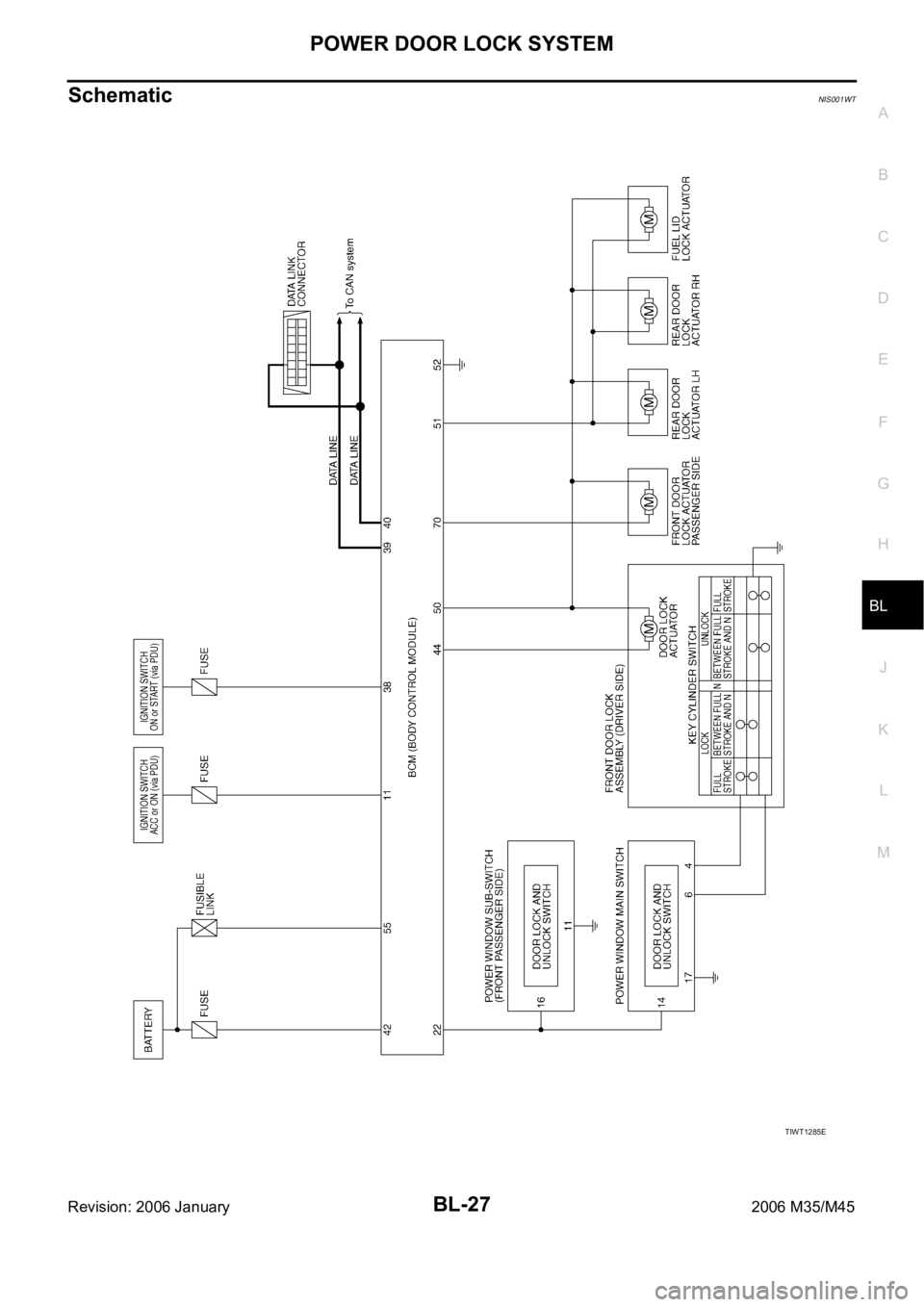
Power is supplied at all times
through 50A fusible link (letter F , located in the fuse and fusible link box).
to BCM terminal 55,
through 10A fuse [No. 21, located in the fuse block (J/B)]
to BCM terminal 42.
When ignition switch is in ACC or ON position, power is supplied
through 10A fuse [No. 6, located in fuse block (J/B)]
to BCM terminal 11.
When ignition switch is in ON or START position, power is supplied
through 15A fuse [No. 1, located in fuse block (J/B)]
to BCM terminal 38.
Ground is supplied
to BCM terminal 52
through body grounds M16 and M70.
When the door is locked or unlocked with power window main switch (door lock and unlock switch), ground is
supplied
to CPU of power window main switch
through power window main switch (door lock and unlock switch) terminal 17
through grounds M16 and M70.
Then power window main switch (door lock and unlock switch) operation signal is sent.
to BCM terminal 22
from power window main switch (door lock and unlock switch) terminal 14
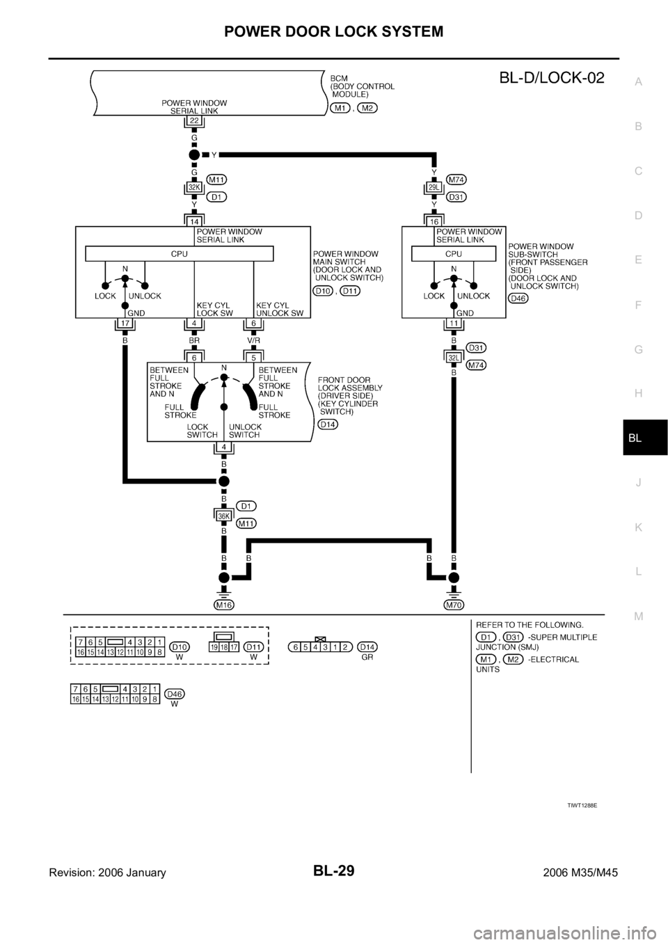
When the door is locked or unlocked with power window sub-switch (front passenger side) (door lock and
unlock switch), ground is supplied
to CPU of power window sub-switch
through power window sub-switch (front passenger side) (door lock and unlock switch) terminal 11
through grounds M16 and M70.
Then power window sub-switch (front passenger side) (door lock and unlock switch) operation signal is sent
to BCM terminal 22
from power window sub-switch (front passenger side) (door lock and unlock switch) terminal 16.
When the door is locked with front door key cylinder switch (driver side), ground is supplied
to CPU of power window main switch
through power window main switch (door lock and unlock switch) terminal 4
through front door key cylinder switch (driver side) terminals 6 and 4
through grounds M16 and M70.
Then front door key cylinder switch (driver side) operation signal (lock) is sent
to BCM terminal 22
from power window main switch (door lock and unlock switch) terminal 14
When the door is unlocked with front door key cylinder switch (driver side), ground is supplied
to CPU of power window main switch
through power window main switch (door lock and unlock switch) terminal 6
through front door key cylinder switch (driver side) terminals 5 and 4
through grounds M16 and M70.
Then front door key cylinder switch (driver side) operation signal (unlock) is sent
to BCM terminal 22
from power window main switch (door lock and unlock switch) terminal 14
BCM is connected to power window main switch and power window sub-switch as serial link.
Page 965 of 5621
BL-26
POWER DOOR LOCK SYSTEM
Revision: 2006 January2006 M35/M45
DOOR LOCK ACTUATOR OPERATION
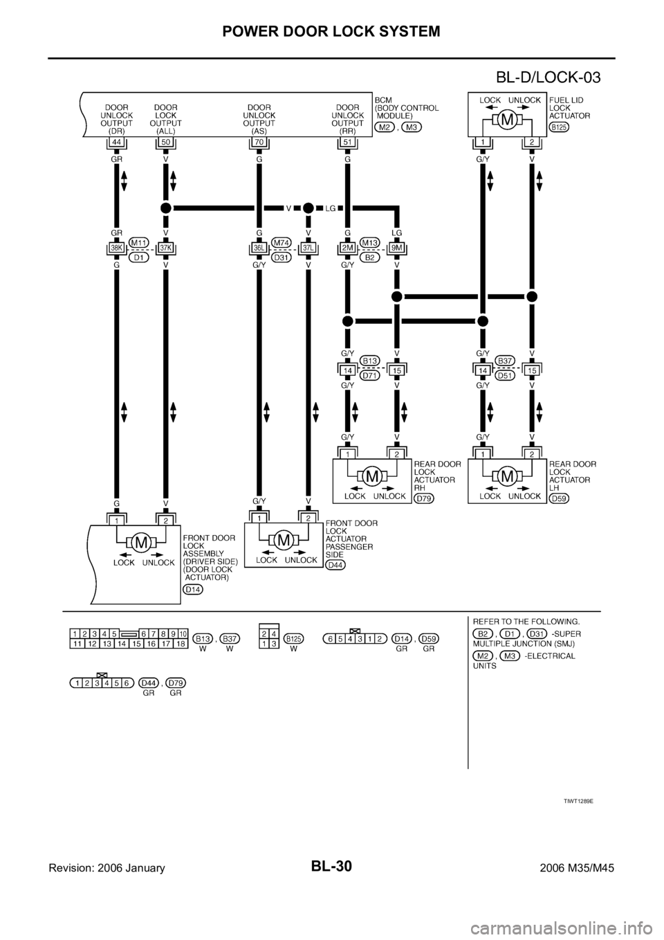
When door is locked with door lock and unlock switch, all door lock actuator is locked. Ground is supplied
to BCM terminal 50
through each door lock actuator terminals 2 and 1
through BCM terminals 44 (driver side), 70 (passenger side) and 51 (rear door).
When door is unlocked with door lock and unlock switch, all door lock actuator is unlocked. Ground is supplied
to BCM terminals 44 (driver side), 70 (passenger side) and 51 (rear door)
through each door lock actuator terminals 1 and 2
through BCM terminal 50.
FUEL LID OPERATION
When door is locked with door lock and unlock switch, fuel lid lock actuator is locked. Ground is supplied
to BCM terminal 50
through fuel lid lock actuator terminals 2 and 1
through BCM terminal 51.
When door is unlocked with door lock and unlock switch, fuel lid lock actuator is unlocked. Ground is supplied
to BCM terminal 51
through fuel lid lock actuator terminals 1 and 2
through BCM terminal 50.
In this condition, fuel lid can be opened if it is pushed.
OUTLINE
Functions Available by Operating the Door Lock and Unlock Switches on Driver's Door and
Passenger's Door
Interlocked with the locking operation of door lock and unlock switch, door lock actuators of all doors and
fuel lid lock actuator are locked.
Interlocked with the unlocking operation of door lock and unlock switch, door lock actuators of all doors
and fuel lid lock actuator are unlocked.
Functions Available by Operating the Key Cylinder Switch on Driver's Door
Interlocked with the locking operation of door key cylinder, door lock actuators of all doors and fuel lid lock
actuator are locked.
Selective Unlock Operation
When door key cylinder is unlocked, door lock actuator driver side and fuel lid lock actuator are unlocked.
When door key cylinder is unlocked for the second time within 5 seconds after the first operation, door
lock actuators on all doors are unlocked.
Select unlock operation mode can be changed using “DOOR LOCK-UNLOCK SET” mode in “WORK SUP-
PORT”. Refer to BL-83, "
WORK SUPPORT" .
Key Reminder Door System
Refer to BL-50, "Key Reminder Function" .
CAN Communication System DescriptionNIS001WR
CAN (Controller Area Network) is a serial communication line for real time application. It is an on-vehicle mul-
tiplex communication line with high data communication speed and excellent error detection ability. Many elec-
tronic control units are equipped onto a vehicle, and each control unit shares information and links with other
control units during operation (not independent). In CAN communication, control units are connected with 2
communication lines (CAN H line, CAN L line) allowing a high rate of information transmission with less wiring.
Each control unit transmits/receives data but selectively reads required data only.
CAN Communication UnitNIS001WS
Refer to LAN-34, "CAN Communication Unit" .
Page 966 of 5621
POWER DOOR LOCK SYSTEM
BL-27
C
D
E
F
G
H
J
K
L
MA
B
BL
Revision: 2006 January2006 M35/M45
SchematicNIS001WT
TIWT1285E
Page 967 of 5621

BL-28
POWER DOOR LOCK SYSTEM
Revision: 2006 January2006 M35/M45
Wiring Diagram —D/LOCK—NIS001WU
TIWT1286E
Page 968 of 5621
POWER DOOR LOCK SYSTEM
BL-29
C
D
E
F
G
H
J
K
L
MA
B
BL
Revision: 2006 January2006 M35/M45
TIWT1288E
Page 969 of 5621
BL-30
POWER DOOR LOCK SYSTEM
Revision: 2006 January2006 M35/M45
TIWT1289E
Page 970 of 5621

POWER DOOR LOCK SYSTEM
BL-31
C
D
E
F
G
H
J
K
L
MA
B
BL
Revision: 2006 January2006 M35/M45
Terminals and Reference Value of BCMNIS001WV
Work FlowNIS001WW
1. Check the symptom and customer's requests.
2. Understand the outline of system. Refer to BL-25, "
System Description" .
3. According to the trouble diagnosis chart by symptom, repair or replace the cause of the malfunction.
Refer to BL-34, "
Trouble Diagnosis Chart by Symptom" .
4. Does power door lock system operate normally?
YES: GO TO 5.
NO: GO TO 3.
5. INSPECTION END
Termi-
nalWire
colorItem ConditionVoltage [V]
(Approx.)
11 V Ignition switch (ACC) Ignition switch is in ACC position Battery voltage
22 G Power window serial link Ignition switch ON
38 W Ignition switch (ON)Ignition switch is in ON or START posi-
tionBattery voltage
39 L CAN H — —
40 P CAN L — —
42 P Battery source (Fuse) — Battery voltage
44 GRDriver door lock actuator
(unlock) signalDoor lock / unlock switch
(Free
Unlock)0 Battery voltage 0
50 V Door lock actuator (lock) signalDoor lock / unlock switch
(Free
Lock)0 Battery voltage 0
51 GRear doors lock actuator and
fuel lid lock actuator (unlock) sig-
nalDoor lock / unlock switch
(Free
Unlock)0 Battery voltage 0
52 B Ground — 0
55 W Power source (Fusible link) — Battery voltage
70 GFront door lock actuator (pas-
senger side) lock signalDoor lock / unlock switch
(Free
Unlock)0 Battery voltage 0
PIIA2344J
Page 971 of 5621

BL-32
POWER DOOR LOCK SYSTEM
Revision: 2006 January2006 M35/M45
CONSULT-II Function (BCM)NIS001WX
CONSULT-II can display each diagnostic item using the diagnostic test modes shown following.
CONSULT-II INSPECTION PROCEDURE
CAUTION:
If CONSULT-II is used with no connection of CONSULT-II CONVERTER, malfunction might be detected
in self-diagnosis depending on control unit which carry out CAN communication.
1. Turn ignition switch “OFF”.
2. Connect “CONSULT-II” and “CONSULT-II CONVERTER” to the
data link connector (1).
3. Turn ignition switch “ON”.
4. Touch “START”. (NISSAN BASED VHCL)
5. Touch “BCM” on “SELECT SYSTEM” screen.
If “BCM” is not indicated, go to GI-40, "
CONSULT-II Data Link
Connector (DLC) Circuit" .
BCM diagnosis
partInspection item, self-diagnosis
modeContent
Door lockDATA MONITOR Displays the input data of BCM in real time basis.
ACTIVE TEST Give a drive signals to load to check the operation check.
PBIB2712E
BCIA0029E
BCIA0030E