drain bolt INFINITI M35 2006 Factory User Guide
[x] Cancel search | Manufacturer: INFINITI, Model Year: 2006, Model line: M35, Model: INFINITI M35 2006Pages: 5621, PDF Size: 65.56 MB
Page 346 of 5621

ON-VEHICLE SERVICE
AT-267
D
E
F
G
H
I
J
K
L
MA
B
AT
Revision: 2006 January2006 M35/M45
i. Apply recommended sealant (Genuine Anaerobic Liquid Gasket
or equivalent. Refer to GI-48, "
Recommended Chemical Prod-
ucts and Sealants" .) to output shaft & companion flange com-
plement as shown in the figure.
CAUTION:
Completely remove all moisture, oil and old sealant, etc.
from the transmission case and output shaft & companion
flange complement mounting surfaces.
ii. Install output shaft & companion flange complement to transmis-
sion case.
iii. Tighten output shaft & companion flange complement bolts (1)
to the specified torque. Refer to AT- 2 6 1 , "
REMOVAL AND
INSTALLATION" .
: Bolt (10)
CAUTION:
Do not reuse self-sealing bolts (2).
Refer to GI section to make sure icons (symbol marks) in the fig-
ure. Refer to GI-11, "
Components" .
5. Install rear engine mounting member. Refer to AT-271, "
Removal and Installation (2WD Models)" .
6. Install oil pan to transmission case.
a. Install oil pan gasket to oil pan.
CAUTION:
Do not reuse oil pan gasket.
Install it in the direction to align hole positions.
Complete remove all moisture, oil and old gasket, etc. from oil pan gasket mounting surface.
b. Install oil pan (with oil pan gasket) to transmission case.
CAUTION:
Install it so that drain plug comes to the position as
shown in the figure.
Be careful not to pinch harnesses.
Completely remove all moisture, oil and old gasket, etc.
from oil pan mounting surface.
SCIA5212E
SCIA5688E
SCIA6943E
SCIA2308E
Page 347 of 5621

AT-268
ON-VEHICLE SERVICE
Revision: 2006 January2006 M35/M45
c. Tighten oil pan mounting bolts to the specified torque in numeri-
cal order shown in the figure after temporarily tightening them.
Tighten necessary oil pan mounting bolts with specified torque.
Refer to AT-261, "
REMOVAL AND INSTALLATION" .
CAUTION:
Do not reuse oil pan mounting bolts.
7. Install drain plug to oil pan. Tighten a necessary drain plug with
specified torque. Refer to AT- 2 6 1 , "
REMOVAL AND INSTALLA-
TION" .
CAUTION:
Do not reuse drain plug gasket.
8. Install control rod. Refer to AT-226, "
Control Rod Removal and Installation" .
9. Install rear propeller shaft. Refer to PR-8, "
Removal and Installation" .
10. Install exhaust front tube and center muffler. Refer to EX-5, "
Removal and Installation" .
11. Pour ATF into A/T assembly. Refer to AT- 1 2 , "
Changing A/T Fluid" .
12. Connect the battery cable to the negative terminal.
SCIA4113E
Page 352 of 5621

TRANSMISSION ASSEMBLY
AT-273
D
E
F
G
H
I
J
K
L
MA
B
AT
Revision: 2006 January2006 M35/M45
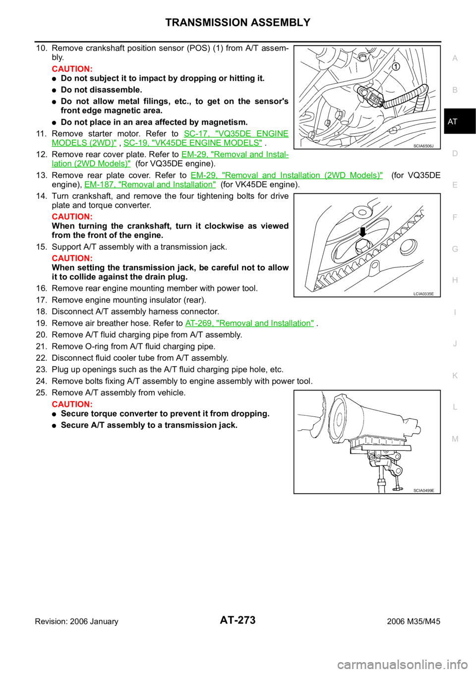
10. Remove crankshaft position sensor (POS) (1) from A/T assem-
bly.
CAUTION:
Do not subject it to impact by dropping or hitting it.
Do not disassemble.
Do not allow metal filings, etc., to get on the sensor's
front edge magnetic area.
Do not place in an area affected by magnetism.
11. Remove starter motor. Refer to SC-17, "
VQ35DE ENGINE
MODELS (2WD)" , SC-19, "VK45DE ENGINE MODELS" .
12. Remove rear cover plate. Refer to EM-29, "
Removal and Instal-
lation (2WD Models)" (for VQ35DE engine).
13. Remove rear plate cover. Refer to EM-29, "
Removal and Installation (2WD Models)" (for VQ35DE
engine), EM-187, "
Removal and Installation" (for VK45DE engine).
14. Turn crankshaft, and remove the four tightening bolts for drive
plate and torque converter.
CAUTION:
When turning the crankshaft, turn it clockwise as viewed
from the front of the engine.
15. Support A/T assembly with a transmission jack.
CAUTION:
When setting the transmission jack, be careful not to allow
it to collide against the drain plug.
16. Remove rear engine mounting member with power tool.
17. Remove engine mounting insulator (rear).
18. Disconnect A/T assembly harness connector.
19. Remove air breather hose. Refer to AT-269, "
Removal and Installation" .
20. Remove A/T fluid charging pipe from A/T assembly.
21. Remove O-ring from A/T fluid charging pipe.
22. Disconnect fluid cooler tube from A/T assembly.
23. Plug up openings such as the A/T fluid charging pipe hole, etc.
24. Remove bolts fixing A/T assembly to engine assembly with power tool.
25. Remove A/T assembly from vehicle.
CAUTION:
Secure torque converter to prevent it from dropping.
Secure A/T assembly to a transmission jack.
SCIA6506J
LCIA0335E
SCIA0499E
Page 355 of 5621

AT-276
TRANSMISSION ASSEMBLY
Revision: 2006 January2006 M35/M45
5. Remove heat insulator.
6. Remove rear propeller shaft. Refer to PR-8, "
Removal and Installation" .
7. Remove front cross bar with power tool. Refer to FSU-26, "
Removal and Installation" .
8. Remove exhaust mounting bracket. Refer to EX-5, "
Removal and Installation" .
9. Remove three way catalyst. Refer to EX-5, "
Removal and Installation" .
10. Remove front propeller shaft. Refer to PR-5, "
Removal and Installation" .
11. Remove control rod. Refer to AT-226, "
Control Rod Removal and Installation" .
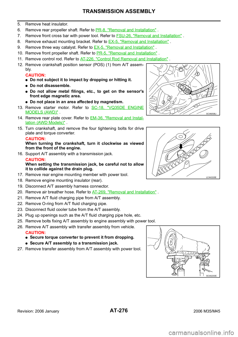
12. Remove crankshaft position sensor (POS) (1) from A/T assem-
bly.
CAUTION:
Do not subject it to impact by dropping or hitting it.
Do not disassemble.
Do not allow metal filings, etc., to get on the sensor's
front edge magnetic area.
Do not place in an area affected by magnetism.
13. Remove starter motor. Refer to SC-18, "
VQ35DE ENGINE
MODELS (AWD)" .
14. Remove rear plate cover. Refer to EM-36, "
Removal and Instal-
lation (AWD Models)" .
15. Turn crankshaft, and remove the four tightening bolts for drive
plate and torque converter.
CAUTION:
When turning the crankshaft, turn it clockwise as viewed
from the front of the engine.
16. Support A/T assembly with a transmission jack.
CAUTION:
When setting the transmission jack, be careful not to allow
it to collide against the drain plug.
17. Remove rear engine mounting member with power tool.
18. Remove engine mounting insulator (rear).
19. Disconnect A/T assembly harness connector.
20. Remove air breather hose. Refer to AT- 2 6 9 , "
Removal and Installation" .
21. Remove A/T fluid charging pipe from A/T assembly.
22. Remove O-ring from A/T fluid charging pipe.
23. Disconnect fluid cooler tube from the A/T assembly.
24. Plug up openings such as the A/T fluid charging pipe hole, etc.
25. Remove bolts fixing A/T assembly to engine assembly with power tool.
26. Remove A/T assembly with transfer assembly from vehicle.
CAUTION:
Secure torque converter to prevent it from dropping.
Secure A/T assembly to a transmission jack.
27. Remove transfer assembly from A/T assembly with power tool.
SCIA6506J
LCIA0335E
SCIA2203E
Page 366 of 5621

OVERHAUL
AT-287
D
E
F
G
H
I
J
K
L
MA
B
AT
Revision: 2006 January2006 M35/M45
7. Pawl shaft 8. Seal ring 9. Needle bearing
10. Revolution sensor 11. Parking gear 12. Output shaft
13. Bearing race 14. Needle bearing 15. Manual plate
16. Parking rod 17. Manual shaft oil seal 18. Manual shaft
19. O-ring 20. Band servo anchor end pin 21. Detent spring
22. Spacer 23. Seal ring 24. Snap ring
25. Return spring 26. O-ring 27. Servo assembly
28. Snap ring 29. Sub-harness 30. Control valve with TCM
31. Bracket 32. A/T fluid temperature sensor 2 33. Oil pan
34. Magnet 35. Drain plug 36. Drain plug gasket
37. Oil pan mounting bolt 38. Oil pan gasket 39. Terminal cord assembly
40. O-ring 41. Retaining pin 42. Transmission case
Refer to GI section to make sure icons (symbol marks) in the figure. Refer to GI-11, "
Components" .
However, refer to the following symbols for others.
*:Apply Genuine Anaerobic Liquid Gasket or equivalent. Refer to GI-48, "Recommended Chemical Products and Sealants"
.
Page 368 of 5621

OVERHAUL
AT-289
D
E
F
G
H
I
J
K
L
MA
B
AT
Revision: 2006 January2006 M35/M45
1. Output shaft & companion flange
complement2. Parking actuator support 3. Parking pawl
4. Return spring 5. Pawl shaft 6. Self-sealing bolt
7. Seal ring 8. Needle bearing 9. Revolution sensor
10. Intermediate shaft 11. Manual plate 12. Parking rod
13. Manual shaft oil seal 14. Manual shaft 15. Retaining pin
16. O-ring 17. Band servo anchor end pin 18. Detent spring
19. Spacer 20. Return spring 21. Seal ring
22. O-ring 23. Servo assembly 24. Snap ring
25. Snap ring 26. Sub-harness 27. Control valve with TCM
28. Bracket 29. A/T fluid temperature sensor 2 30. Terminal cord assembly
31. O-ring 32. Oil pan 33. Magnet
34. Drain plug 35. Drain plug gasket 36. Oil pan mounting bolt
37. Oil pan gasket 38. Transmission case
Refer to GI section to make sure icons (symbol marks) in the figure. Refer to GI-11, "
Components" .
However, refer to the following symbols for others.
*:Apply Genuine Anaerobic Liquid Gasket or equivalent. Refer to GI-48, "Recommended Chemical Products and Sealants" .
Page 370 of 5621

OVERHAUL
AT-291
D
E
F
G
H
I
J
K
L
MA
B
AT
Revision: 2006 January2006 M35/M45
7. Pawl shaft 8. Self-sealing bolt 9. Seal ring
10. Needle bearing 11. Gasket 12. Revolution sensor
13. Parking gear 14. Output shaft 15. Bearing race
16. Needle bearing 17. Manual plate 18. Parking rod
19. Manual shaft oil seal 20. Manual shaft 21. O-ring
22. Band servo anchor end pin 23. Detent spring 24. Spacer
25. Seal ring 26. Snap ring 27. Return spring
28. O-ring 29. Servo assembly 30. Snap ring
31. Sub-harness 32. Control valve with TCM 33. Bracket
34. A/T fluid temperature sensor 2 35. Oil pan 36. Magnet
37. Drain plug 38. Drain plug gasket 39. Oil pan mounting bolt
40. Oil pan gasket 41. Terminal cord assembly 42. O-ring
43. Retaining pin 44. Transmission case
Refer to GI section to make sure icons (symbol marks) in the figure. Refer to GI-11, "
Components" .
Page 443 of 5621

AT-364
ASSEMBLY
Revision: 2006 January2006 M35/M45
b. Install oil pan to transmission case.
CAUTION:
Install it so that drain plug comes to the position as
shown in the figure.
Be careful not to pinch harnesses.
Completely remove all moisture, oil and old gasket, etc.
from oil pan mounting surface.
c. Tighten oil pan mounting bolts to the specified torque in numeri-
cal order shown in the figure after temporarily tightening them.
Tighten oil pan mounting bolts to the specified torque. Refer to
AT-278, "
Components" .
CAUTION:
Do not reuse oil pan mounting bolts.
18. Install drain plug to oil pan. Tighten drain plug to the specified
torque. Refer to AT-278, "
Components" .
CAUTION:
Do not reuse drain plug gasket.
19. Install torque converter.
a. Pour ATF into torque converter.
Approximately 2 liter (2-1/8 US qt, 1-3/4 Imp qt) of ATF is
required for a new torque converter.
When reusing old torque converter, add the same amount
of ATF as was drained.
b. Install torque converter while aligning notches of torque con-
verter with notches of oil pump.
CAUTION:
Install torque converter while rotating it.
c. Measure distance “A” to make sure that torque converter is in
proper position.
SCIA2308E
SCIA4113E
SAT428DA
SCIA5010E
Distance “A”
VQ35DE models: 25.0 mm (0.98 in) or more
VK45DE models: 22.0 mm (0.87 in) or more
SCIA5694E
Page 582 of 5621

HEATER & COOLING UNIT ASSEMBLY
ATC-135
C
D
E
F
G
H
I
K
L
MA
B
AT C
Revision: 2006 January2006 M35/M45
HEATER & COOLING UNIT ASSEMBLYPFP:27110
Removal and InstallationNJS000HF
REMOVAL
1. Use a refrigerant collecting equipment (for HFC-134a) to discharge the refrigerant.
2. Drain coolant from cooling system. Refer to CO-11, "
Changing Engine Coolant" (VQ35DE) or CO-40,
"Changing Engine Coolant" (VK45DE).
3. Remove cowl top cover. Refer to EI-18, "
COWL TOP" .
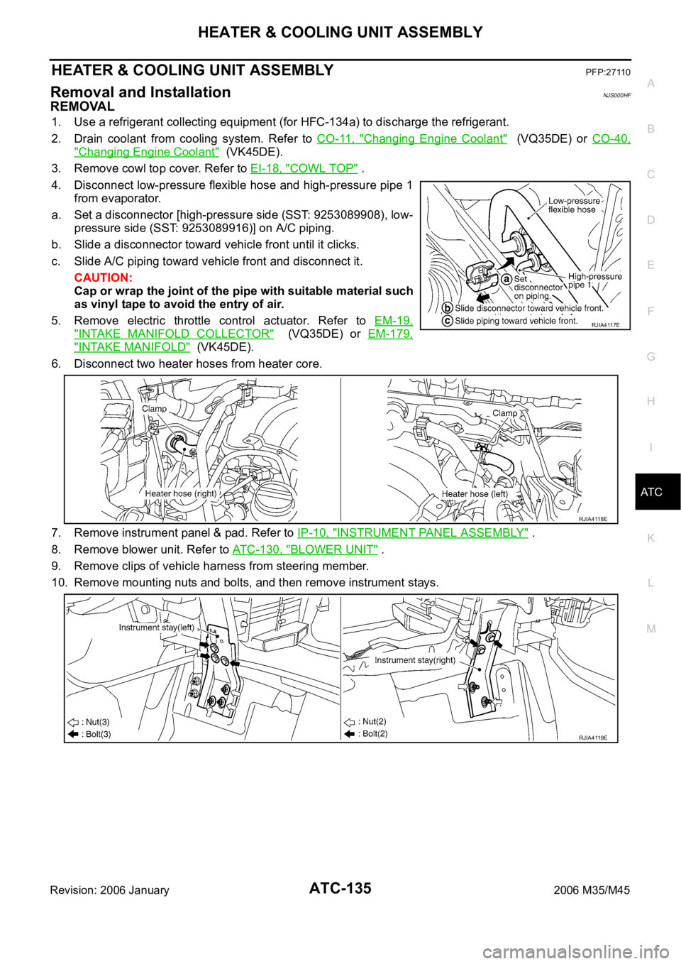
4. Disconnect low-pressure flexible hose and high-pressure pipe 1
from evaporator.
a. Set a disconnector [high-pressure side (SST: 9253089908), low-
pressure side (SST: 9253089916)] on A/C piping.
b. Slide a disconnector toward vehicle front until it clicks.
c. Slide A/C piping toward vehicle front and disconnect it.
CAUTION:
Cap or wrap the joint of the pipe with suitable material such
as vinyl tape to avoid the entry of air.
5. Remove electric throttle control actuator. Refer to EM-19,
"INTAKE MANIFOLD COLLECTOR" (VQ35DE) or EM-179,
"INTAKE MANIFOLD" (VK45DE).
6. Disconnect two heater hoses from heater core.
7. Remove instrument panel & pad. Refer to IP-10, "
INSTRUMENT PANEL ASSEMBLY" .
8. Remove blower unit. Refer to ATC-130, "
BLOWER UNIT" .
9. Remove clips of vehicle harness from steering member.
10. Remove mounting nuts and bolts, and then remove instrument stays.
RJIA4117E
RJIA4118E
RJIA4119E
Page 583 of 5621

ATC-136
HEATER & COOLING UNIT ASSEMBLY
Revision: 2006 January2006 M35/M45
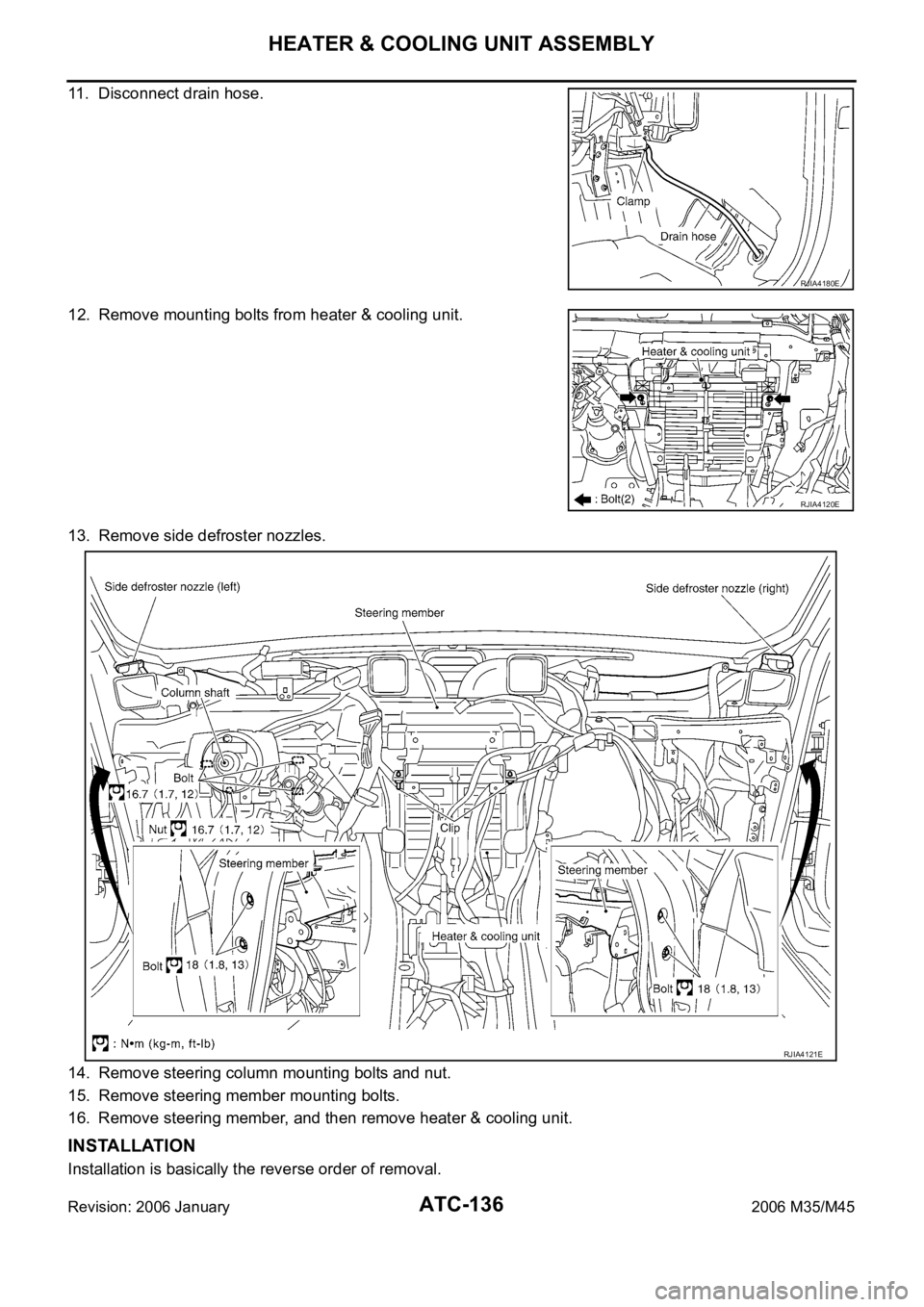
11. Disconnect drain hose.
12. Remove mounting bolts from heater & cooling unit.
13. Remove side defroster nozzles.
14. Remove steering column mounting bolts and nut.
15. Remove steering member mounting bolts.
16. Remove steering member, and then remove heater & cooling unit.
INSTALLATION
Installation is basically the reverse order of removal.
RJIA4180E
RJIA4120E
RJIA4121E