ECU INFINITI M35 2006 Factory Service Manual
[x] Cancel search | Manufacturer: INFINITI, Model Year: 2006, Model line: M35, Model: INFINITI M35 2006Pages: 5621, PDF Size: 65.56 MB
Page 3027 of 5621
EI-22
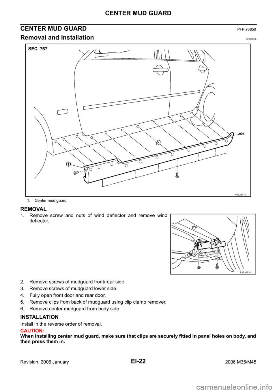
CENTER MUD GUARD
Revision: 2006 January2006 M35/M45
CENTER MUD GUARDPFP:76850
Removal and InstallationNIS0024L
REMOVAL
1. Remove screw and nuts of wind deflector and remove wind
deflector.
2. Remove screws of mudguard front/rear side.
3. Remove screws of mudguard lower side.
4. Fully open front door and rear door.
5. Remove clips from back of mudguard using clip clamp remover.
6. Remove center mudguard from body side.
INSTALLATION
Install in the reverse order of removal.
CAUTION:
When installing center mud guard, make sure that clips are securely fitted in panel holes on body, and
then press them in.
1. Center mud guard
PIIB2941J
PIIB3973J
Page 3030 of 5621
ROOF SIDE MOLDING
EI-25
C
D
E
F
G
H
J
K
L
MA
B
EI
Revision: 2006 January2006 M35/M45
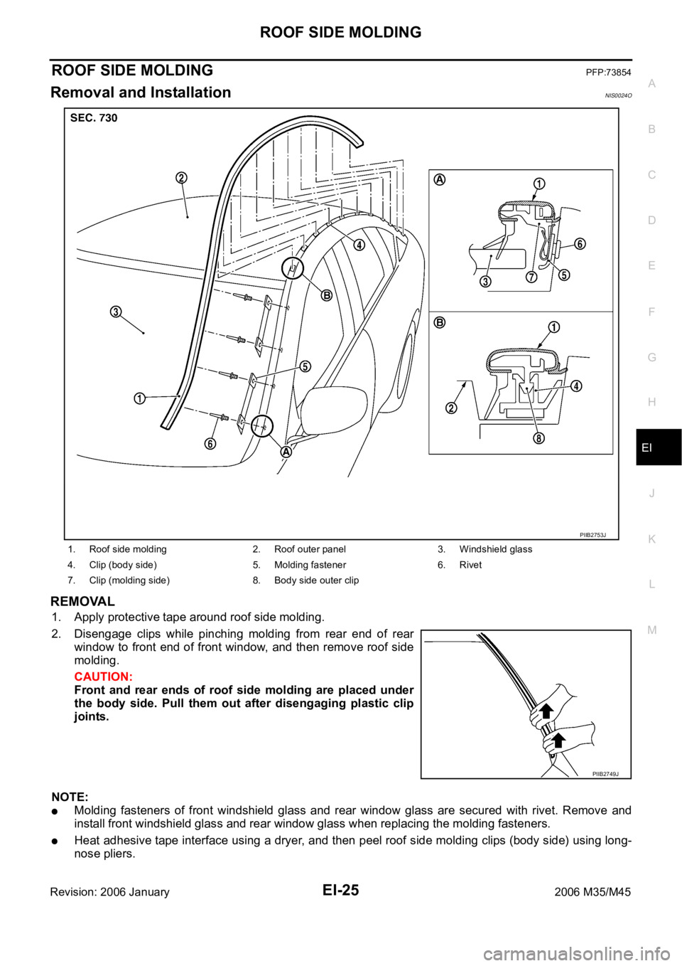
ROOF SIDE MOLDINGPFP:73854
Removal and InstallationNIS0024O
REMOVAL
1. Apply protective tape around roof side molding.
2. Disengage clips while pinching molding from rear end of rear
window to front end of front window, and then remove roof side
molding.
CAUTION:
Front and rear ends of roof side molding are placed under
the body side. Pull them out after disengaging plastic clip
joints.
NOTE:
Molding fasteners of front windshield glass and rear window glass are secured with rivet. Remove and
install front windshield glass and rear window glass when replacing the molding fasteners.
Heat adhesive tape interface using a dryer, and then peel roof side molding clips (body side) using long-
nose pliers.
1. Roof side molding 2. Roof outer panel 3. Windshield glass
4. Clip (body side) 5. Molding fastener 6. Rivet
7. Clip (molding side) 8. Body side outer clip
PIIB2753J
PIIB2749J
Page 3033 of 5621
EI-28
DOOR SASH MOLDING
Revision: 2006 January2006 M35/M45
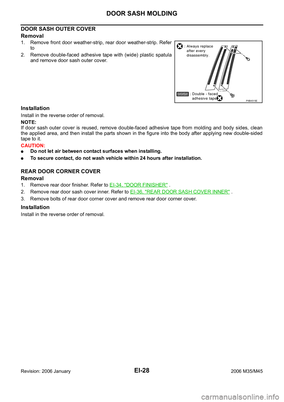
DOOR SASH OUTER COVER
Removal
1. Remove front door weather-strip, rear door weather-strip. Refer
to
2. Remove double-faced adhesive tape with (wide) plastic spatula
and remove door sash outer cover.
Installation
Install in the reverse order of removal.
NOTE:
If door sash outer cover is reused, remove double-faced adhesive tape from molding and body sides, clean
the applied area, and then install the parts shown in the figure into the body after applying new double-sided
tape to it.
CAUTION:
Do not let air between contact surfaces when installing.
To secure contact, do not wash vehicle within 24 hours after installation.
REAR DOOR CORNER COVER
Removal
1. Remove rear door finisher. Refer to EI-34, "DOOR FINISHER" .
2. Remove rear door sash cover inner. Refer to EI-36, "
REAR DOOR SASH COVER INNER" .
3. Remove bolts of rear door corner cover and remove rear door corner cover.
Installation
Install in the reverse order of removal.
PIIB4515E
Page 3036 of 5621
SIDE GUARD MOLDING
EI-31
C
D
E
F
G
H
J
K
L
MA
B
EI
Revision: 2006 January2006 M35/M45
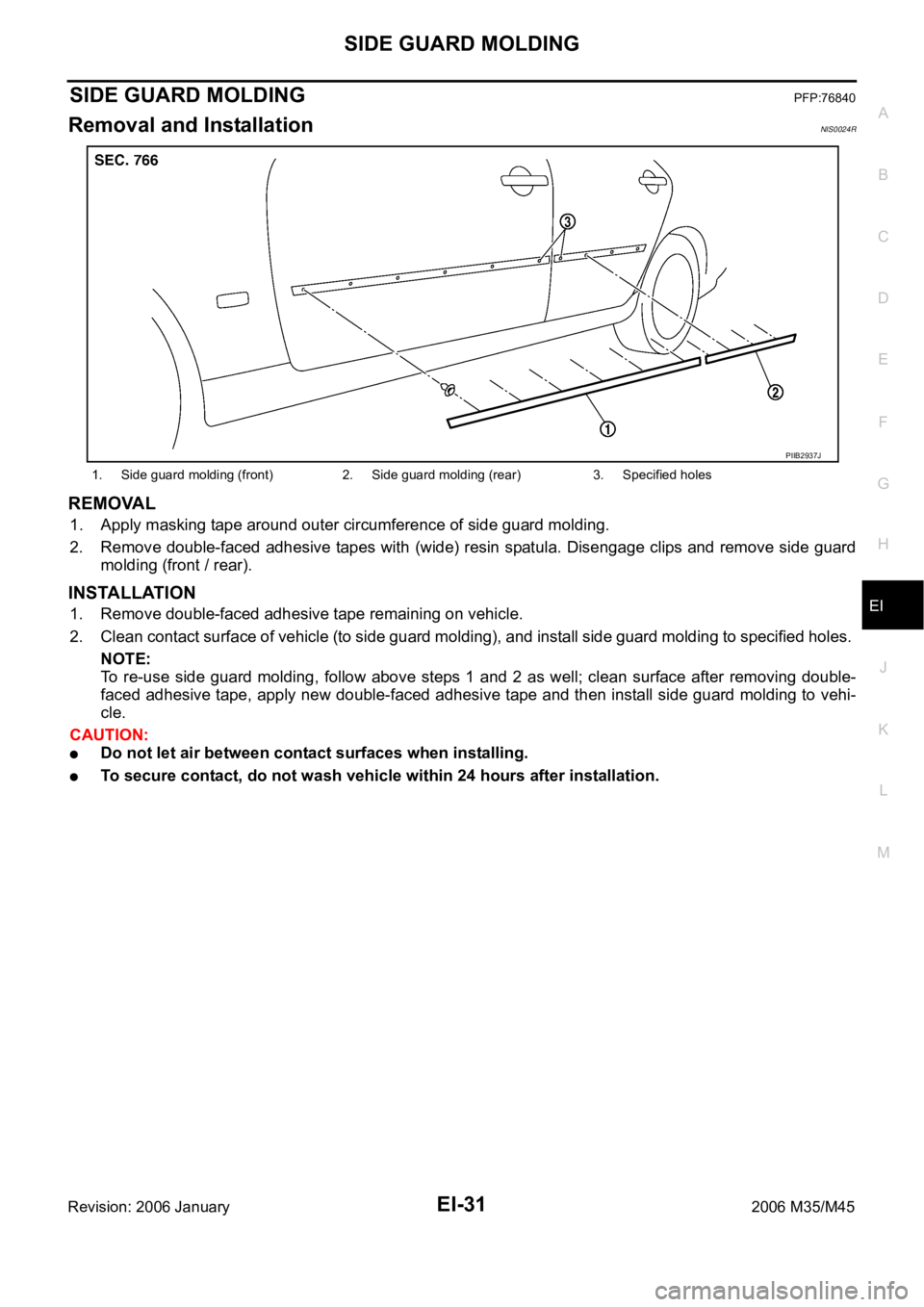
SIDE GUARD MOLDINGPFP:76840
Removal and InstallationNIS0024R
REMOVAL
1. Apply masking tape around outer circumference of side guard molding.
2. Remove double-faced adhesive tapes with (wide) resin spatula. Disengage clips and remove side guard
molding (front / rear).
INSTALLATION
1. Remove double-faced adhesive tape remaining on vehicle.
2. Clean contact surface of vehicle (to side guard molding), and install side guard molding to specified holes.
NOTE:
To re-use side guard molding, follow above steps 1 and 2 as well; clean surface after removing double-
faced adhesive tape, apply new double-faced adhesive tape and then install side guard molding to vehi-
cle.
CAUTION:
Do not let air between contact surfaces when installing.
To secure contact, do not wash vehicle within 24 hours after installation.
1. Side guard molding (front) 2. Side guard molding (rear) 3. Specified holes
PIIB2937J
Page 3040 of 5621
DOOR FINISHER
EI-35
C
D
E
F
G
H
J
K
L
MA
B
EI
Revision: 2006 January2006 M35/M45
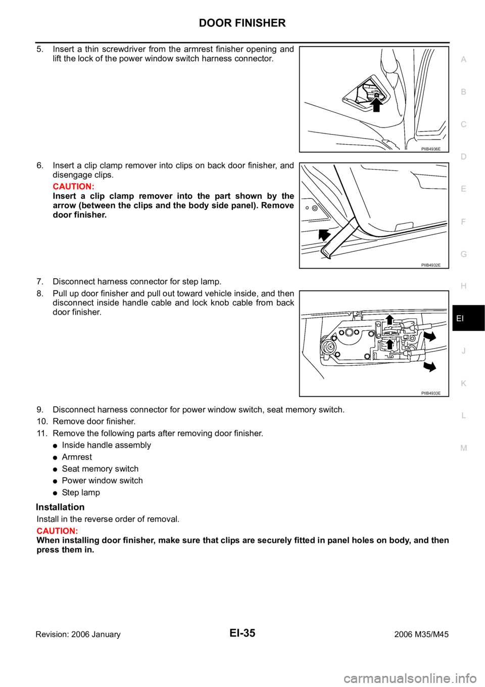
5. Insert a thin screwdriver from the armrest finisher opening and
lift the lock of the power window switch harness connector.
6. Insert a clip clamp remover into clips on back door finisher, and
disengage clips.
CAUTION:
Insert a clip clamp remover into the part shown by the
arrow (between the clips and the body side panel). Remove
door finisher.
7. Disconnect harness connector for step lamp.
8. Pull up door finisher and pull out toward vehicle inside, and then
disconnect inside handle cable and lock knob cable from back
door finisher.
9. Disconnect harness connector for power window switch, seat memory switch.
10. Remove door finisher.
11. Remove the following parts after removing door finisher.
Inside handle assembly
Armrest
Seat memory switch
Power window switch
St e p l am p
Installation
Install in the reverse order of removal.
CAUTION:
When installing door finisher, make sure that clips are securely fitted in panel holes on body, and then
press them in.
PIIB4936E
PIIB4932E
PIIB4933E
Page 3046 of 5621
BODY SIDE TRIM
EI-41
C
D
E
F
G
H
J
K
L
MA
B
EI
Revision: 2006 January2006 M35/M45
REAR WHEEL HOUSE GARNISH
Removal
1. Remove rear seat cushion and rear seatback. Refer to SE-176, "Removal and Installation" .
2. Remove rear body side welt.
3. Remove clip of rear wheel house garnish.
4. Remove rear wheel house garnish.
Installation
Install in the reverse order of removal.
NOTE:
To install, check if all clips are matched over holes of panel on vehicle, then push on.
REAR PILLAR FINISHER
Removal
1. Remove rear seat cushion and rear seatback. Refer to SE-176, "Removal and Installation" .
2. Remove rear seat belt floor anchor bolt. Refer to SB-32, "
Removal and Installation of Rear Seat Belt" .
3. Remove rear kicking plate inner.
4. Remove rear wheel house garnish.
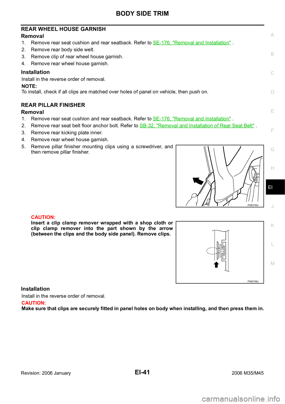
5. Remove pillar finisher mounting clips using a screwdriver, and
then remove pillar finisher.
CAUTION:
Insert a clip clamp remover wrapped with a shop cloth or
clip clamp remover into the part shown by the arrow
(between the clips and the body side panel). Remove clips.
Installation
Install in the reverse order of removal.
CAUTION:
Make sure that clips are securely fitted in panel holes on body when installing, and then press them in.
PIIB2769J
PIIB2768J
Page 3048 of 5621

REAR PARCEL SHELF FINISHER
EI-43
C
D
E
F
G
H
J
K
L
MA
B
EI
Revision: 2006 January2006 M35/M45
5. Disconnect high-mounted stop lamp harness connector from
front side of rear parcel shelf finisher. (Models with rear window
sunshade)
6. Remove rear parcel shelf finisher mounting clip using a clip clamp remover.
7. Remove the following parts after removing rear parcel shelf finisher.
Rear speaker grille (for woofer)
High-mounted stop lamp
High-mounted stop lamp harness
INSTALLATION
Install in the reverse order of removal.
CAUTION:
Make sure that clips are securely fitted in panel holes on body when installing, and then press them in.
Rear Window SunshadeNIS0024X
REMOVAL AND INSTALLATION
CAUTION:
Be careful not to damage the rear window glass.
Removal
1. Remove rear parcel shelf finisher. Refer to EI-42, "REAR PARCEL SHELF FINISHER" .
2. Disconnect rear window sunshade harness connector.
3. Remove rear window sunshade mounting bolts.
4. Lift up rear window sunshade and pull out locating pin from body side panel hole, and then remove rear
window sunshade.
Installation
Install in the reverse order of removal.
PIIB5130E
Page 3058 of 5621
HEADLINING
EI-53
C
D
E
F
G
H
J
K
L
MA
B
EI
Revision: 2006 January2006 M35/M45
REMOVAL
1. Remove front pillar garnish (LH/RH). Refer to EI-37, "BODY SIDE TRIM" .
2. Remove roof harness and antenna feeder securing clip using a clip clamp remover after removing front
pillar garnish (LH/RH), and then disconnect roof harness and antenna feeder connectors.
3. Remove rear seat cushion and seatback. Refer to SE-172, "
REAR SEAT" .
4. Remove front kicking plate inner, center pillar lower garnish, center pillar upper garnish, front body side
welt, rear kicking plate inner, rear wheelhouse garnish, rear pillar finisher, rear body side welt. Refer to EI-
37, "BODY SIDE TRIM" .
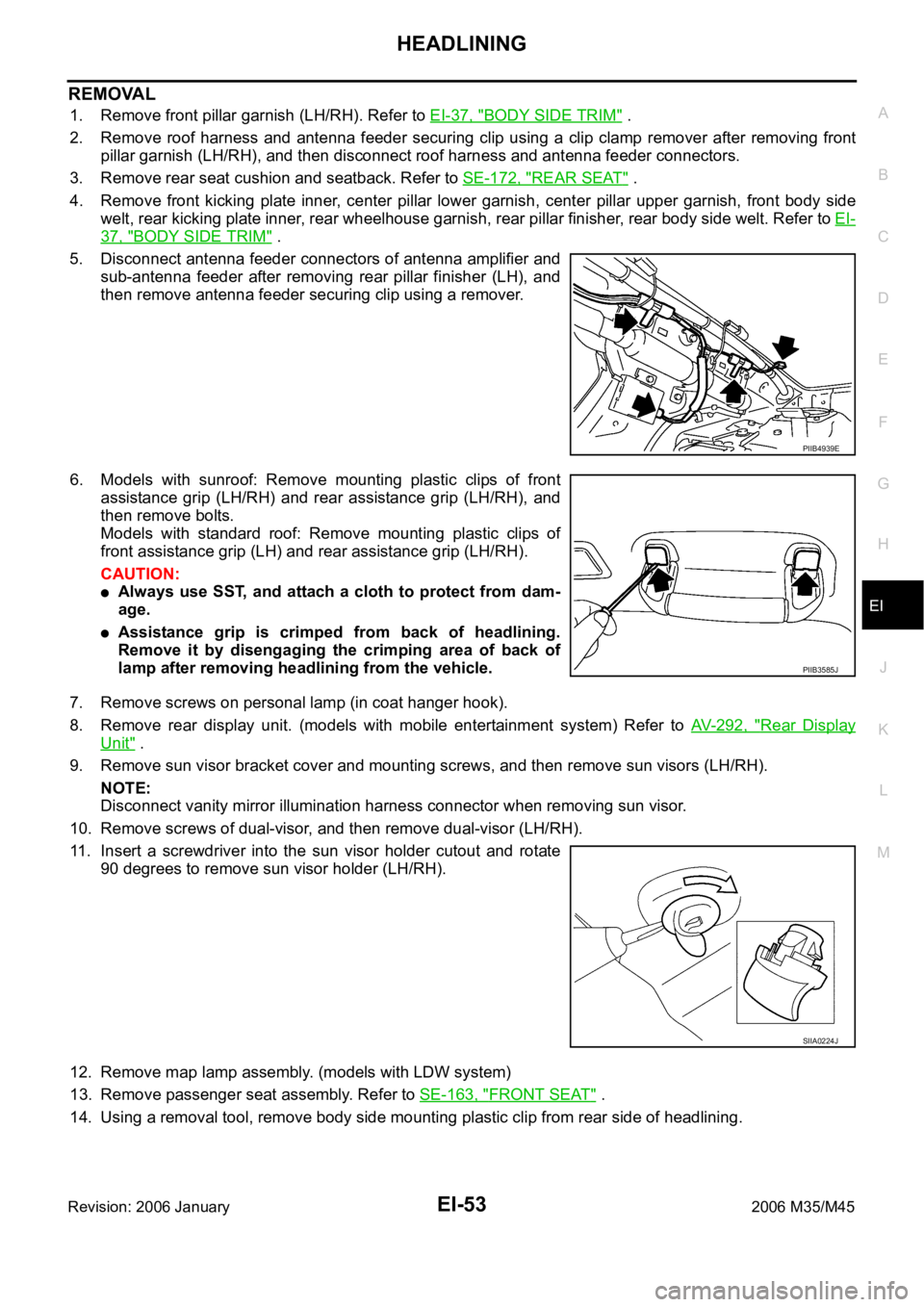
5. Disconnect antenna feeder connectors of antenna amplifier and
sub-antenna feeder after removing rear pillar finisher (LH), and
then remove antenna feeder securing clip using a remover.
6. Models with sunroof: Remove mounting plastic clips of front
assistance grip (LH/RH) and rear assistance grip (LH/RH), and
then remove bolts.
Models with standard roof: Remove mounting plastic clips of
front assistance grip (LH) and rear assistance grip (LH/RH).
CAUTION:
Always use SST, and attach a cloth to protect from dam-
age.
Assistance grip is crimped from back of headlining.
Remove it by disengaging the crimping area of back of
lamp after removing headlining from the vehicle.
7. Remove screws on personal lamp (in coat hanger hook).
8. Remove rear display unit. (models with mobile entertainment system) Refer to AV- 2 9 2 , "
Rear Display
Unit" .
9. Remove sun visor bracket cover and mounting screws, and then remove sun visors (LH/RH).
NOTE:
Disconnect vanity mirror illumination harness connector when removing sun visor.
10. Remove screws of dual-visor, and then remove dual-visor (LH/RH).
11. Insert a screwdriver into the sun visor holder cutout and rotate
90 degrees to remove sun visor holder (LH/RH).
12. Remove map lamp assembly. (models with LDW system)
13. Remove passenger seat assembly. Refer to SE-163, "
FRONT SEAT" .
14. Using a removal tool, remove body side mounting plastic clip from rear side of headlining.
PIIB4939E
PIIB3585J
SIIA0224J
Page 3077 of 5621
![INFINITI M35 2006 Factory Service Manual EM-14
[VQ35DE]
ENGINE ROOM COVER
Revision: 2006 January2006 M35/M45
ENGINE ROOM COVERPFP:14049
ComponentsNBS004MS
Removal and InstallationNBS004MT
REMOVAL
CAUTION:
Do not damage or scratch cover when INFINITI M35 2006 Factory Service Manual EM-14
[VQ35DE]
ENGINE ROOM COVER
Revision: 2006 January2006 M35/M45
ENGINE ROOM COVERPFP:14049
ComponentsNBS004MS
Removal and InstallationNBS004MT
REMOVAL
CAUTION:
Do not damage or scratch cover when](/img/42/57023/w960_57023-3076.png)
EM-14
[VQ35DE]
ENGINE ROOM COVER
Revision: 2006 January2006 M35/M45
ENGINE ROOM COVERPFP:14049
ComponentsNBS004MS
Removal and InstallationNBS004MT
REMOVAL
CAUTION:
Do not damage or scratch cover when installing or removing.
Refer to EM-19, "INTAKE MANIFOLD COLLECTOR" for removal and installation of engine cover.
Refer to EM-17, "AIR CLEANER AND AIR DUCT" for removal and installation of air duct (inlet).
Remove the washer tank cap before removing the engine room cover (RH).
Remove the engine room covers (RH and LH) by lifting the clipped point using a clip driver.
Major parts and inspection points under each cover are as follows; (numbered as in figure)
1. Upper side of engine assembly
2. Battery, relay box
3. Power steering fluid reservoir tank, engine coolant reservoir tank, relay box
4. Engine assembly front side, drive belts, cooling fan
5. Mass air flow sensor, air cleaner case
6. Brake master cylinder, brake booster
INSTALLATION
Installation is the reverse order of removal.
1. Engine cover 2. Battery cover 3. Engine room cover (RH)
4. Air duct (inlet) 5. Engine room cover (LH) 6. Brake master cylinder cover
A. Clip (secure at back surface)
PBIC3824E
Page 3082 of 5621
![INFINITI M35 2006 Factory Service Manual INTAKE MANIFOLD COLLECTOR
EM-19
[VQ35DE]
C
D
E
F
G
H
I
J
K
L
MA
EM
Revision: 2006 January2006 M35/M45
INTAKE MANIFOLD COLLECTORPFP:14003
ComponentsNBS004N0
Refer to GI-11, "Components" for sy INFINITI M35 2006 Factory Service Manual INTAKE MANIFOLD COLLECTOR
EM-19
[VQ35DE]
C
D
E
F
G
H
I
J
K
L
MA
EM
Revision: 2006 January2006 M35/M45
INTAKE MANIFOLD COLLECTORPFP:14003
ComponentsNBS004N0
Refer to GI-11, "Components" for sy](/img/42/57023/w960_57023-3081.png)
INTAKE MANIFOLD COLLECTOR
EM-19
[VQ35DE]
C
D
E
F
G
H
I
J
K
L
MA
EM
Revision: 2006 January2006 M35/M45
INTAKE MANIFOLD COLLECTORPFP:14003
ComponentsNBS004N0
Refer to GI-11, "Components" for symbol marks in the figure.
Removal and InstallationNBS004N1
REMOVAL
WAR NING :
To avoid the danger of being scalded, never drain engine coolant when the engine is hot.
Gasket for intake manifold collector (upper) is secured together with mounting bolt for intake man-
ifold collector (lower). Thus, even when only gasket for upper side is replaced, gasket for lower
side must be also replaced.
1. Vacuum hose 2.EVAP canister purge volume control
solenoid valve3. Vacuum hose
4. Bracket 5. Intake manifold collector (upper) 6. Water hose
7. Water hose 8. Gasket 9. Electric throttle control actuator
10. Bracket 11. PCV hose 12. Bracket
13. Gasket 14. Intake manifold collector (lower) 15. Gasket
16. Intake manifold collector cover
A. To vacuum pipe B. To water outlet C. To heater pipe
D. To PCV valve
KBIA3590J