SFU INFINITI M35 2006 Factory Owner's Manual
[x] Cancel search | Manufacturer: INFINITI, Model Year: 2006, Model line: M35, Model: INFINITI M35 2006Pages: 5621, PDF Size: 65.56 MB
Page 2351 of 5621
![INFINITI M35 2006 Factory Owners Manual EC-808
[VK45DE]
BASIC SERVICE PROCEDURE
Revision: 2006 January2006 M35/M45
6. Touch “START” and wait 20 seconds.
7. Make sure that “CMPLT” is displayed on CONSULT-II screen. If
“CMPLT” is INFINITI M35 2006 Factory Owners Manual EC-808
[VK45DE]
BASIC SERVICE PROCEDURE
Revision: 2006 January2006 M35/M45
6. Touch “START” and wait 20 seconds.
7. Make sure that “CMPLT” is displayed on CONSULT-II screen. If
“CMPLT” is](/img/42/57023/w960_57023-2350.png)
EC-808
[VK45DE]
BASIC SERVICE PROCEDURE
Revision: 2006 January2006 M35/M45
6. Touch “START” and wait 20 seconds.
7. Make sure that “CMPLT” is displayed on CONSULT-II screen. If
“CMPLT” is not displayed, Idle Air Volume Learning will not be
carried out successfully. In this case, find the cause of the inci-
dent by referring to the DIAGNOSTIC PROCEDURE below.
8. Rev up the engine two or three times and make sure that idle
speed and ignition timing are within the specifications.
Without CONSULT-II
NOTE:
It is better to count the time accurately with a clock.
It is impossible to switch the diagnostic mode when an accelerator pedal position sensor circuit
has a malfunction.
1. Perform EC-806, "
Accelerator Pedal Released Position Learning" .
2. Perform EC-806, "
Throttle Valve Closed Position Learning" .
3. Start engine and warm it up to normal operating temperature.
4. Check that all items listed under the topic PREPARATION (previously mentioned) are in good order.
5. Turn ignition switch OFF and wait at least 10 seconds.
6. Confirm that accelerator pedal is fully released, turn ignition switch ON and wait 3 seconds.
7. Repeat the following procedure quickly five times within 5 seconds.
a. Fully depress the accelerator pedal.
b. Fully release the accelerator pedal.
8. Wait 7 seconds, fully depress the accelerator pedal and keep it for approx. 20 seconds until the MIL stops
blinking and turned ON.
9. Fully release the accelerator pedal within 3 seconds after the MIL turned ON.
10. Start engine and let it idle.
11. Wait 20 seconds.
12. Rev up the engine two or three times and make sure that idle speed and ignition timing are within the
specifications.
SEF454Y
ITEM SPECIFICATION
Idle speed 650
50 rpm (in P or N position)
Ignition timing 12
5 BTDC (in P or N position)MBIB0238E
SEC897C
Page 2352 of 5621
![INFINITI M35 2006 Factory Owners Manual BASIC SERVICE PROCEDURE
EC-809
[VK45DE]
C
D
E
F
G
H
I
J
K
L
MA
EC
Revision: 2006 January2006 M35/M4513. If idle speed and ignition timing are not within the specification, Idle Air Volume Learning wil INFINITI M35 2006 Factory Owners Manual BASIC SERVICE PROCEDURE
EC-809
[VK45DE]
C
D
E
F
G
H
I
J
K
L
MA
EC
Revision: 2006 January2006 M35/M4513. If idle speed and ignition timing are not within the specification, Idle Air Volume Learning wil](/img/42/57023/w960_57023-2351.png)
BASIC SERVICE PROCEDURE
EC-809
[VK45DE]
C
D
E
F
G
H
I
J
K
L
MA
EC
Revision: 2006 January2006 M35/M4513. If idle speed and ignition timing are not within the specification, Idle Air Volume Learning will not be carried
out successfully. In this case, find the cause of the incident by referring to the Diagnostic Procedure below.
DIAGNOSTIC PROCEDURE
If idle air volume learning cannot be performed successfully, proceed as follows:
1.Check that throttle valve is fully closed.
2.Check PCV valve operation.
3.Check that downstream of throttle valve is free from air leakage.
4.When the above three items check out OK, engine component parts and their installation condi-
tion are questionable. Check and eliminate the cause of the incident.
It is useful to perform EC-868, "
TROUBLE DIAGNOSIS - SPECIFICATION VALUE" .
5.If any of the following conditions occur after the engine has started, eliminate the cause of the
incident and perform Idle Air Volume Learning all over again:
Engine stalls.
Erroneous idle.
Fuel Pressure CheckNBS005AD
FUEL PRESSURE RELEASE
With CONSULT-II
1. Turn ignition switch ON.
2. Perform “FUEL PRESSURE RELEASE” in “WORK SUPPORT”
mode with CONSULT-II.
3. Start engine.
4. After engine stalls, crank it two or three times to release all fuel
pressure.
5. Turn ignition switch OFF.
Without CONSULT-II
1. Remove fuel pump fuse (1) located in IPDM E/R (2).
2. Start engine.
3. After engine stalls, crank it 2 or 3 times to release all fuel pres-
sure.
4. Turn ignition switch OFF.
5. Reinstall fuel pump fuse after servicing fuel system.
FUEL PRESSURE CHECK
Before disconnecting fuel line, release fuel pressure from fuel line to eliminate danger.
NOTE:
Prepare pans or saucers under the disconnected fuel line because the fuel may spill out. The fuel
pressure cannot be completely released because Y50 models do not have fuel return system.
Use Fuel Pressure Gauge Kit (J-44321) to check fuel pressure.
1. Release fuel pressure to zero. Refer to EC-809, "
FUEL PRESSURE RELEASE" .
ITEM SPECIFICATION
Idle speed 650
50 rpm (in P or N position)
Ignition timing 12
5 BTDC (in P or N position)
SEF214Y
PBIB2697E
Page 2397 of 5621
![INFINITI M35 2006 Factory Owners Manual EC-854
[VK45DE]
TROUBLE DIAGNOSIS
Revision: 2006 January2006 M35/M45
VEHICLE SPEED
[km/h] or [MPH]The vehicle speed computed from the
vehicle speed signal sent from TCM is
displayed.
IDL A/V LEARN
INFINITI M35 2006 Factory Owners Manual EC-854
[VK45DE]
TROUBLE DIAGNOSIS
Revision: 2006 January2006 M35/M45
VEHICLE SPEED
[km/h] or [MPH]The vehicle speed computed from the
vehicle speed signal sent from TCM is
displayed.
IDL A/V LEARN](/img/42/57023/w960_57023-2396.png)
EC-854
[VK45DE]
TROUBLE DIAGNOSIS
Revision: 2006 January2006 M35/M45
VEHICLE SPEED
[km/h] or [MPH]The vehicle speed computed from the
vehicle speed signal sent from TCM is
displayed.
IDL A/V LEARN
[YET/CMPLT]
Display the condition of idle air volume
learning
YET: Idle air volume learning has not
been performed yet.
CMPLT: Idle air volume learning has
already been performed successfully.
TRVL AFTER MIL
[km] or [mile]
Distance traveled while MIL is activated.
A/F S1 HTR (B1)
[%]
Air fuel ratio (A/F) sensor 1 heater control
value computed by ECM according to the
input signals.
The current flow to the heater becomes
larger as the value increases. A/F S1 HTR (B2)
[%]
AC PRESS SEN
[V]
The signal voltage from the refrigerant
pressure sensor is displayed.
VHCL SPEED SE
[km/h] or [mph]
The vehicle speed computed from the
vehicle speed signal sent from combina-
tion meter is displayed.
SET VHCL SPD
[km/h] or [mph]
The preset vehicle speed is displayed.
MAIN SW
[ON/OFF]
Indicates [ON/OFF] condition from MAIN
switch signal.
CANCEL SW
[ON/OFF]
Indicates [ON/OFF] condition from CAN-
CEL switch signal.
RESUME/ACC SW
[ON/OFF]
Indicates [ON/OFF] condition from
RESUME/ACCELERATE switch signal.
SET SW
[ON/OFF]
Indicates [ON/OFF] condition from SET/
COAST switch signal.
BRAKE SW1
[ON/OFF]
Indicates [ON/OFF] condition from ASCD
brake switch signal.
BRAKE SW2
[ON/OFF]
Indicates [ON/OFF] condition of stop
lamp switch signal.
DIST SW
[ON/OFF]
Indicates [ON/OFF] condition from DIS-
TANCE switch signal.
CRUISE LAMP
[ON/OFF]
Indicates [ON/OFF] condition of CRUISE
lamp determined by the ECM according
to the input signals.
SET LAMP
[ON/OFF]
Indicates [ON/OFF] condition of SET
lamp determined by the ECM according
to the input signals.
FAN DUTY
Indicates a command value for cooling
fan. The value is calculated by ECM
based on input signals.
AC EVA TEMP
Indicates A/C evaporator temperature
sent from “unified meter and A/C amp.”.
AC EVA TARGET
Indicates target A/C evaporator tempera-
ture sent from “unified meter and A/C
amp.”. Monitored item
[Unit]ECM
INPUT
SIG-
NALSMAIN
SIG-
NALSDescription Remarks
Page 2804 of 5621
![INFINITI M35 2006 Factory Owners Manual DTC P1226 TP SENSOR
EC-1261
[VK45DE]
C
D
E
F
G
H
I
J
K
L
MA
EC
Revision: 2006 January2006 M35/M45
DTC P1226 TP SENSORPFP:16119
Component DescriptionNBS005LA
Electric throttle control actuator cons INFINITI M35 2006 Factory Owners Manual DTC P1226 TP SENSOR
EC-1261
[VK45DE]
C
D
E
F
G
H
I
J
K
L
MA
EC
Revision: 2006 January2006 M35/M45
DTC P1226 TP SENSORPFP:16119
Component DescriptionNBS005LA
Electric throttle control actuator cons](/img/42/57023/w960_57023-2803.png)
DTC P1226 TP SENSOR
EC-1261
[VK45DE]
C
D
E
F
G
H
I
J
K
L
MA
EC
Revision: 2006 January2006 M35/M45
DTC P1226 TP SENSORPFP:16119
Component DescriptionNBS005LA
Electric throttle control actuator consists of throttle control motor,
throttle position sensor, etc. The throttle position sensor responds to
the throttle valve movement.
The throttle position sensor has the two sensors. These sensors are
a kind of potentiometers which transform the throttle valve position
into output voltage, and emit the voltage signal to the ECM. In addi-
tion, these sensors detect the opening and closing speed of the
throttle valve and feed the voltage signals to the ECM. The ECM
judges the current opening angle of the throttle valve from these sig-
nals and the ECM controls the throttle control motor to make the
throttle valve opening angle properly in response to driving condi-
tion.
On Board Diagnosis LogicNBS005LB
The MIL will not light up for this diagnosis.
DTC Confirmation ProcedureNBS005LC
NOTE:
If DTC Confirmation Procedure has been previously conducted, always turn ignition switch OFF and wait at
least 10 seconds before conducting the next test.
TESTING CONDITION:
Before performing the following procedure, confirm that battery voltage is more than 10V at idle.
WITH CONSULT-II
1. Turn ignition switch ON.
2. Select “DATA MONITOR” mode with CONSULT-II.
3. Turn ignition switch OFF, wait at least 10 seconds.
4. Turn ignition switch ON.
5. Repeat steps 3 and 4 for 32 times.
6. If 1st trip DTC is detected, go to EC-1262, "
Diagnostic Proce-
dure" .
WITH GST
Follow the procedure “WITH CONSULT-II” above.
PBIB0145E
DTC No. Trouble diagnosis name DTC detecting condition Possible cause
P1226
1226Closed throttle position
learning performanceClosed throttle position learning is not per-
formed successfully, repeatedly.
Electric throttle control actuator
(TP sensor 1 and 2)
SEF058Y
Page 3373 of 5621

FAX-14
FRONT DRIVE SHAFT
Revision: 2006 January2006 M35/M45
6. Remove snap ring. Remove spider assembly from the shaft.
7. Remove boot from the shaft.
8. Remove dust cover from housing. (RH side)
9. Clean old grease on housing with paper towels.
Wheel Side
1. Secure shaft in a vise.
CAUTION:
Protect shaft when securing in a vise using aluminum or, copper plates.
2. Remove boot bands, and then remove boot from joint sub-assembly.
3. Screw the drive shaft puller (suitable tool) 30 mm (1.18 in) or
more onto the thread on joint sub-assembly, and pull joint sub-
assembly out of shaft.
CAUTION:
Replace entire drive shaft assembly if joint sub-assembly
cannot be removed after five or more unsuccessful
attempts.
Align sliding hammer and drive shaft and remove them
by pulling firmly and uniformly.
4. Remove circular clip from shaft.
5. Remove boot from shaft.
6. Clean old grease on joint sub-assembly with paper towels while rotating ball cage.
INSPECTION AFTER DISASSEMBLY
Shaft
Check shaft for runout, cracks, or other damage. Replace if there are.
Joint Sub-Assembly (Wheel Side)
Check the following:
Joint sub-assembly for rough rotation and excessive axial looseness.
The inside of the joint sub-assembly for entry of foreign material.
Joint sub-assembly for compression scars, cracks, and fractures inside of joint sub-assembly.
Replace joint sub-assembly if there are any non-standard conditions of components.
Housing and Spider assembly (Front Final Drive side)
Replace housing and spider assembly if there is scratching or wear of housing roller contact surface or spider
roller contact surface.
NOTE:
Housing and spider assembly are used in a set.
SFA612
SDIA0606E
Page 4853 of 5621

PG-26
IPDM E/R (INTELLIGENT POWER DISTRIBUTION MODULE ENGINE ROOM)
Revision: 2006 January2006 M35/M45
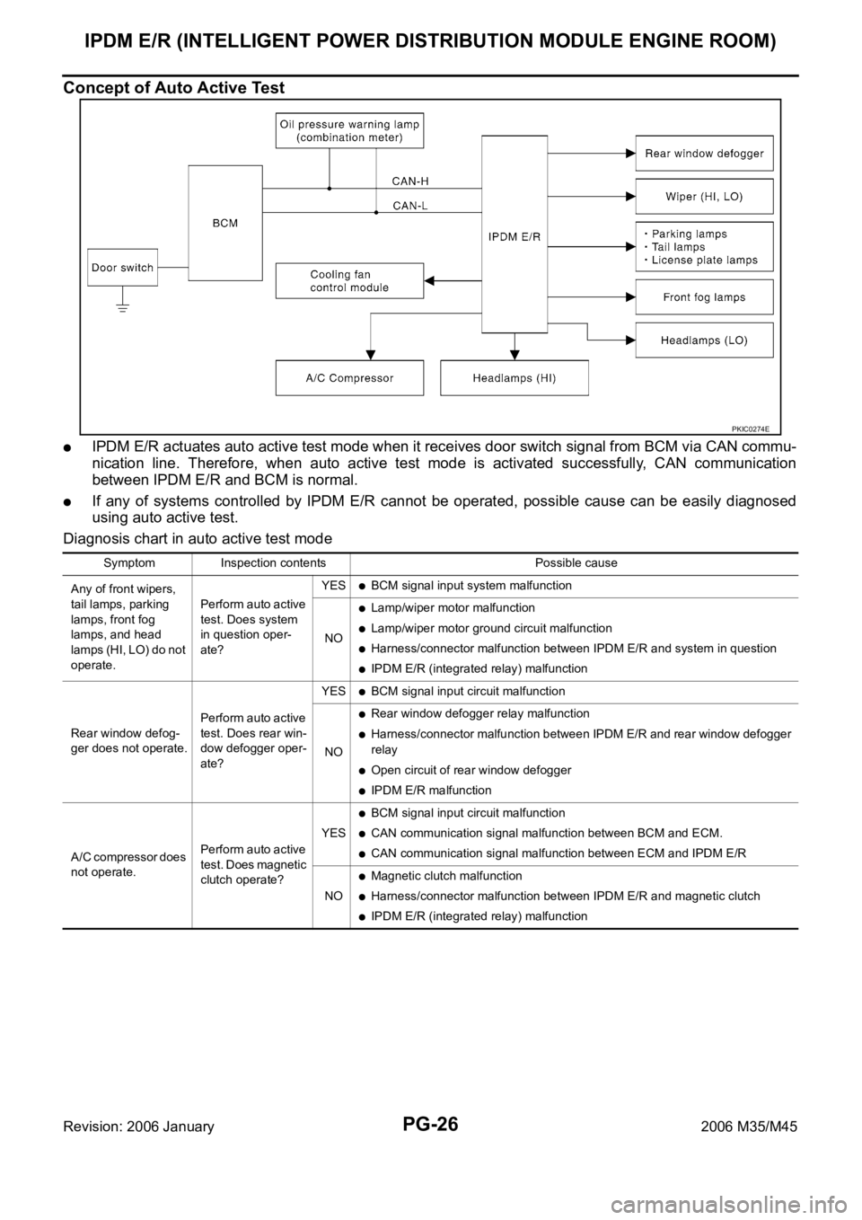
Concept of Auto Active Test
IPDM E/R actuates auto active test mode when it receives door switch signal from BCM via CAN commu-
nication line. Therefore, when auto active test mode is activated successfully, CAN communication
between IPDM E/R and BCM is normal.
If any of systems controlled by IPDM E/R cannot be operated, possible cause can be easily diagnosed
using auto active test.
Diagnosis chart in auto active test mode
PKIC0274E
Symptom Inspection contents Possible cause
Any of front wipers,
tail lamps, parking
lamps, front fog
lamps, and head
lamps (HI, LO) do not
operate.Perform auto active
test. Does system
in question oper-
ate?YES
BCM signal input system malfunction
NO
Lamp/wiper motor malfunction
Lamp/wiper motor ground circuit malfunction
Harness/connector malfunction between IPDM E/R and system in question
IPDM E/R (integrated relay) malfunction
Rear window defog-
ger does not operate.Perform auto active
test. Does rear win-
dow defogger oper-
ate?YES
BCM signal input circuit malfunction
NO
Rear window defogger relay malfunction
Harness/connector malfunction between IPDM E/R and rear window defogger
relay
Open circuit of rear window defogger
IPDM E/R malfunction
A/C compressor does
not operate.Perform auto active
test. Does magnetic
clutch operate?YES
BCM signal input circuit malfunction
CAN communication signal malfunction between BCM and ECM.
CAN communication signal malfunction between ECM and IPDM E/R
NO
Magnetic clutch malfunction
Harness/connector malfunction between IPDM E/R and magnetic clutch
IPDM E/R (integrated relay) malfunction
Page 5009 of 5621

RAX-10
REAR DRIVE SHAFT
Revision: 2006 January2006 M35/M45
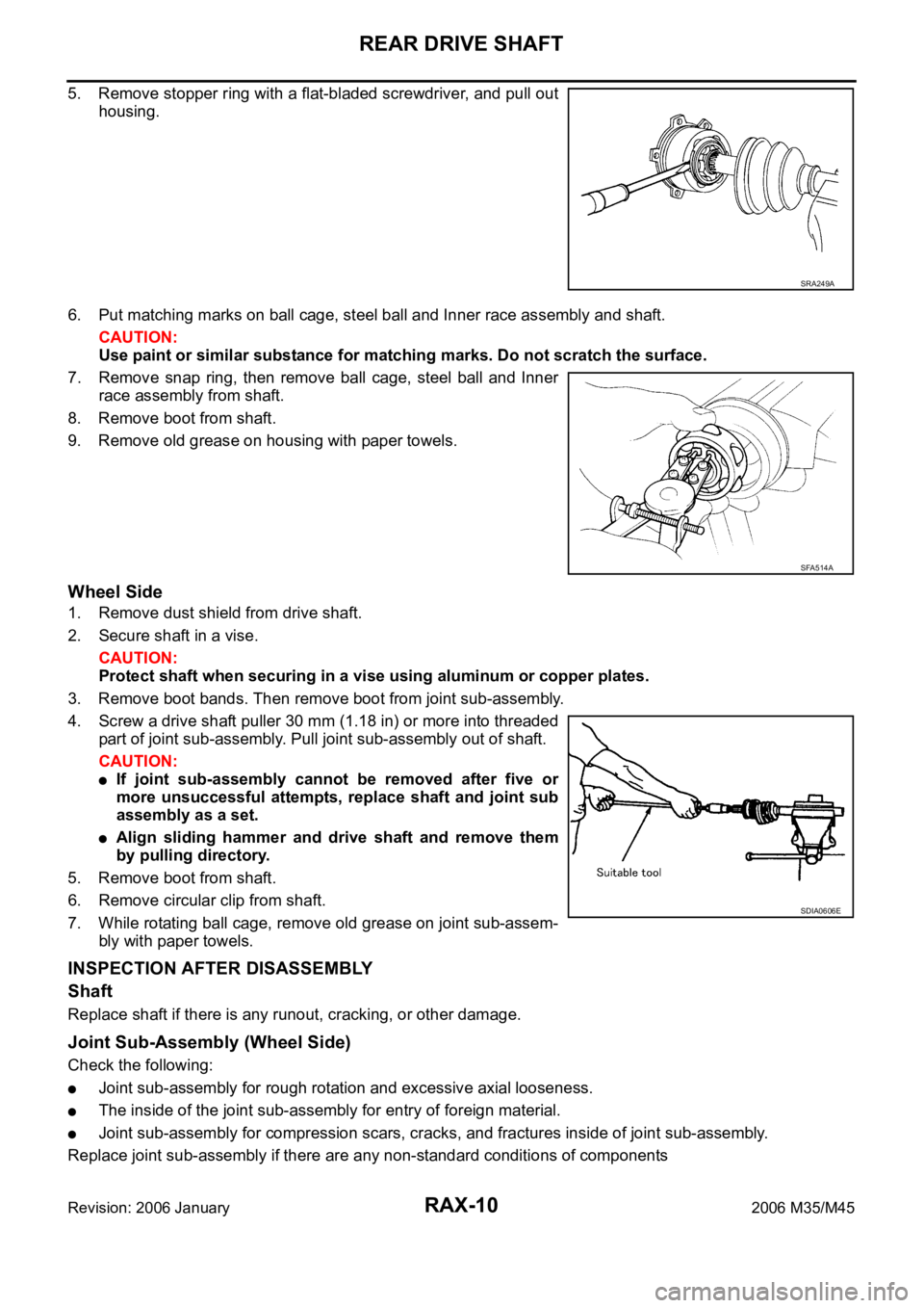
5. Remove stopper ring with a flat-bladed screwdriver, and pull out
housing.
6. Put matching marks on ball cage, steel ball and Inner race assembly and shaft.
CAUTION:
Use paint or similar substance for matching marks. Do not scratch the surface.
7. Remove snap ring, then remove ball cage, steel ball and Inner
race assembly from shaft.
8. Remove boot from shaft.
9. Remove old grease on housing with paper towels.
Wheel Side
1. Remove dust shield from drive shaft.
2. Secure shaft in a vise.
CAUTION:
Protect shaft when securing in a vise using aluminum or copper plates.
3. Remove boot bands. Then remove boot from joint sub-assembly.
4. Screw a drive shaft puller 30 mm (1.18 in) or more into threaded
part of joint sub-assembly. Pull joint sub-assembly out of shaft.
CAUTION:
If joint sub-assembly cannot be removed after five or
more unsuccessful attempts, replace shaft and joint sub
assembly as a set.
Align sliding hammer and drive shaft and remove them
by pulling directory.
5. Remove boot from shaft.
6. Remove circular clip from shaft.
7. While rotating ball cage, remove old grease on joint sub-assem-
bly with paper towels.
INSPECTION AFTER DISASSEMBLY
Shaft
Replace shaft if there is any runout, cracking, or other damage.
Joint Sub-Assembly (Wheel Side)
Check the following:
Joint sub-assembly for rough rotation and excessive axial looseness.
The inside of the joint sub-assembly for entry of foreign material.
Joint sub-assembly for compression scars, cracks, and fractures inside of joint sub-assembly.
Replace joint sub-assembly if there are any non-standard conditions of components
SRA249A
SFA514A
SDIA0606E
Page 5070 of 5621

REAR FINAL DRIVE ASSEMBLY
RFD-27
C
E
F
G
H
I
J
K
L
MA
B
RFD
Revision: 2006 January2006 M35/M45
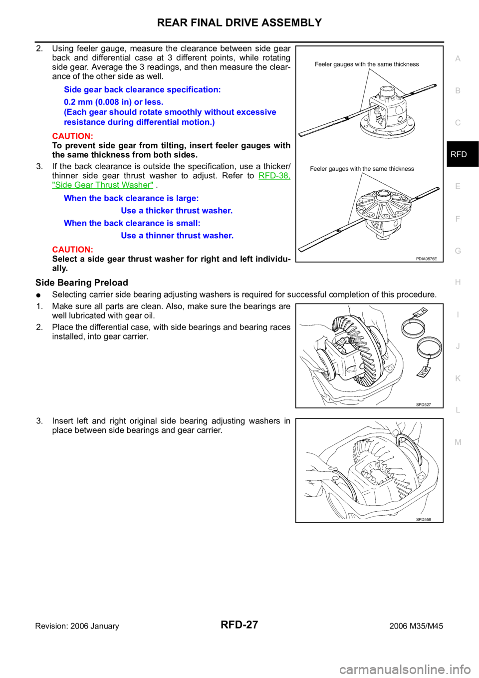
2. Using feeler gauge, measure the clearance between side gear
back and differential case at 3 different points, while rotating
side gear. Average the 3 readings, and then measure the clear-
ance of the other side as well.
CAUTION:
To prevent side gear from tilting, insert feeler gauges with
the same thickness from both sides.
3. If the back clearance is outside the specification, use a thicker/
thinner side gear thrust washer to adjust. Refer to RFD-38,
"Side Gear Thrust Washer" .
CAUTION:
Select a side gear thrust washer for right and left individu-
ally.
Side Bearing Preload
Selecting carrier side bearing adjusting washers is required for successful completion of this procedure.
1. Make sure all parts are clean. Also, make sure the bearings are
well lubricated with gear oil.
2. Place the differential case, with side bearings and bearing races
installed, into gear carrier.
3. Insert left and right original side bearing adjusting washers in
place between side bearings and gear carrier.Side gear back clearance specification:
0.2 mm (0.008 in) or less.
(Each gear should rotate smoothly without excessive
resistance during differential motion.)
When the back clearance is large:
Use a thicker thrust washer.
When the back clearance is small:
Use a thinner thrust washer.
PDIA0576E
SPD527
SPD558