glove box INFINITI M35 2006 Factory Owner's Manual
[x] Cancel search | Manufacturer: INFINITI, Model Year: 2006, Model line: M35, Model: INFINITI M35 2006Pages: 5621, PDF Size: 65.56 MB
Page 4724 of 5621

ILLUMINATION
LT-297
C
D
E
F
G
H
I
J
L
MA
B
LT
Revision: 2006 January2006 M35/M45
to door mirror remote control switch (illumination) terminal 15
to AFS switch (illumination) terminal 6 (with AFS)
to rear sunshade front switch (illumination) terminal 6 (with rear control switch)
to A/T illumination terminal 2
to snow mode switch (illumination) terminal 6 (ADW models)
to rear control cancel switch (illumination) terminal 5 (with rear control switch)
to clock terminal 4
to multifunction switch terminal 4
to audio unit terminal 8
to DVD player terminal 17 (With DVD player)
to climate controlled seat switch driver side (illumination) terminal 8 (with climate controlled seat) and
to climate controlled seat switch passenger side (illumination) terminal 8 (with climate controlled seat)
through illumination control switch terminal 2
to illumination control switch terminal 3
through grounds M16 and M70,
to cigarette lighter socket (illumination) terminal 1
to map lamp (illumination) terminal 4
to power window main switch illumination terminal 2 and
to glove box lamp terminal 2
through grounds M16 and M70,
to ashtray illumination (rear LH) terminal 2
to ashtray illumination (rear RH) terminal 2
to automatic return cancel switch (illumination) terminal 2 (With rear control switch)
to rear power seat switch LH (illumination) terminal 3 (With rear control switch)
to rear heated seat switch LH (illumination) terminal 8 (With rear control switch)
through grounds B5, B40 and B131,
through rear sunshade cancel relay terminal 7(With rear control switch)
to rear sunshade rear switch (illumination) terminal 7 (With rear control switch)
through grounds B5, B40, B131 and B559.
to rear control switch terminal 4
to rear power seat switch RH (illumination) terminal 3 (With rear control switch)
to rear heated seat switch RH (illumination) terminal 8 (With rear control switch)
through grounds B5, B40, B131 and B559.
With power and ground supplied, illumination lamps illuminate.
EXTERIOR LAMP BATTERY SAVER CONTROL
BCM activates the exterior lamp battery saver control function and turns off the exterior lamps to prevent bat-
tery from over discharge when the combination switch (lighting switch) is in 1ST or 2ND position and/or the
front fog lamp switch ON and the door lock operation is performed by keyless entry system.
CAN Communication System DescriptionNKS003TI
CAN (Controller Area Network) is a serial communication line for real time application. It is an on-vehicle mul-
tiplex communication line with high data communication speed and excellent error detection ability. Many elec-
tronic control units are equipped onto a vehicle, and each control unit shares information and links with other
control units during operation (not independent). In CAN communication, control units are connected with 2
communication lines (CAN H line, CAN L line) allowing a high rate of information transmission with less wiring.
Each control unit transmits/receives data but selectively reads required data only.
CAN Communication UnitNKS003TJ
Refer to LAN-34, "CAN Communication Unit" .
Page 4740 of 5621

ILLUMINATION
LT-313
C
D
E
F
G
H
I
J
L
MA
B
LT
Revision: 2006 January2006 M35/M45
Glove Box LampNKS003TM
BULB REPLACEMENT, REMOVAL AND INSTALLATION
Removal
1. Remove glove box cover. Refer to IP-10, "INSTRUMENT PANEL ASSEMBLY" .
2. Turn globe box lamp bulb socket (1) counterclockwise and
unlock it.
3. Remove bulb (2).
Installation
Installation is the reverse order of removal.
Cigarette Lighter IlluminationNKS003TN
BULB REPLACEMENT, REMOVAL AND INSTALLATION
Removal
1. Remove A/T console finisher. Refer to IP-11, "Removal and Installation of Instrument Panel & Pad" .
2. Remove screws (A).
3. Use a screwdriver to undo hooks, remove bulb sockets (1).
4. Remove bulb (2).
Installation
Installation is the reverse order of removal.Glove box lamp : 12V - 1.4W
SKIB4206E
SKIB4207E
Front ashtray and cigarette lighter
illumination: 12V - 1.4W
SKIB4209E
Page 4742 of 5621

BULB SPECIFICATIONS
LT-315
C
D
E
F
G
H
I
J
L
MA
B
LT
Revision: 2006 January2006 M35/M45
BULB SPECIFICATIONSPFP:26297
HeadlampNKS003TQ
Exterior LampNKS003TR
Interior Lamp/IlluminationNKS003TS
NOTE:
This lamp is used as both front ashtray and front cigarette lighter. Item Wattage (W)
Low (Halogen type)55 (H1)
Low (Xenon type)35 (D2S)
High60 (HB3)
Item Wattage (W)
Front combination lampFront turn signal lamp 21
Parking lamp (Clearance lamp) 5
Front side marker lamp 5
Rear combination lampStop/Tail lamp LED
Rear turn signal lamp 21 (amber)
Rear side marker lamp LED
Back-up lamp18
Side turn signal lamp5
Front fog lamp55 (H11)
License plate lamp5
High-mounted stop lampLED
Item Wattage (W)
Map lamp8
Personal lamp8
Trunk room lampUpper
5
Lower
Front ashtray and front cigarette lighter illumination
NOTE1.4
Rear ashtray illumination1.4
Ste p lamp5
Vanity mirror lamp1.8
Center console indirect illuminationLED
Glove box lamp1.4
Foot lampDriver side
3.4
Passenger side
Kicking plateDriver side
LED
Passenger side
Power window indirect illuminationLED
Page 5023 of 5621

RF-10
SUNROOF
Revision: 2006 January2006 M35/M45
SUNROOFPFP:91210
Component Parts and Harness Connector LocationNIS0023Q
PIIB6291E
1. Fuse block (J/B) 2. Fuse and fusible link box 3. BCM M1, M2, M3
(View with the glove box assembly
removed)
4. Sunroof motor assembly M186 5. Sunroof switch R53 6. Front door switch (driver side) B11
Page 5192 of 5621

AUTOMATIC DRIVE POSITIONER
SE-11
C
D
E
F
G
H
J
K
L
MA
B
SE
Revision: 2006 January2006 M35/M45
AUTOMATIC DRIVE POSITIONERPFP:28491
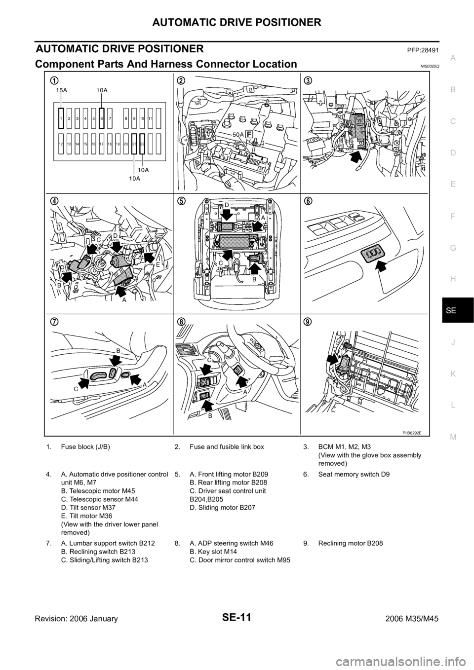
Component Parts And Harness Connector LocationNIS0025Q
PIIB6292E
1. Fuse block (J/B) 2. Fuse and fusible link box 3. BCM M1, M2, M3
(View with the glove box assembly
removed)
4. A. Automatic drive positioner control
unit M6, M7
B. Telescopic motor M45
C. Telescopic sensor M44
D. Tilt sensor M37
E. Tilt motor M36
(View with the driver lower panel
removed)5. A. Front lifting motor B209
B. Rear lifting motor B208
C. Driver seat control unit
B204,B205
D. Sliding motor B2076. Seat memory switch D9
7. A. Lumbar support switch B212
B. Reclining switch B213
C. Sliding/Lifting switch B2138. A. ADP steering switch M46
B. Key slot M14
C. Door mirror control switch M959. Reclining motor B208
Page 5272 of 5621

POWER SEAT(PASSENGER SIDE)
SE-91
C
D
E
F
G
H
J
K
L
MA
B
SE
Revision: 2006 January2006 M35/M45
POWER SEAT(PASSENGER SIDE)PFP:87050
Component Parts and Harness Connector LocationNIS0026Z
PIIB5888E
1. Fuse block (J/B) 2.Fuse, fusible link and relay block (J/
B)3.BCM M2
(View with the glove box cover
removed)
4.Power seat switch B255
a: Reclining switch
b: Sliding and lifting switch5.a: Sliding motor M264
b: Lifting motor M2666. Reclining motor M263
Page 5403 of 5621

SRS-42
FRONT PASSENGER AIR BAG MODULE
Revision: 2006 January2006 M35/M45
FRONT PASSENGER AIR BAG MODULEPFP:K8515
Removal and InstallationNHS0009E
REMOVAL
CAUTION:
Before servicing, turn ignition switch OFF, disconnect both battery terminal and wait at
least 3 minutes.
Do not use air tools or electric tools for servicing.
Always work from the side of air bag module. Do not work from the front of it.
Always place air bag module with pad side facing upward.
Do not use old fixing bolts after removal; replace with new bolts.
Do not make an impact to the air bag module by dropping etc. Replace the air bag module if it has
been dropped or sustained an impact.
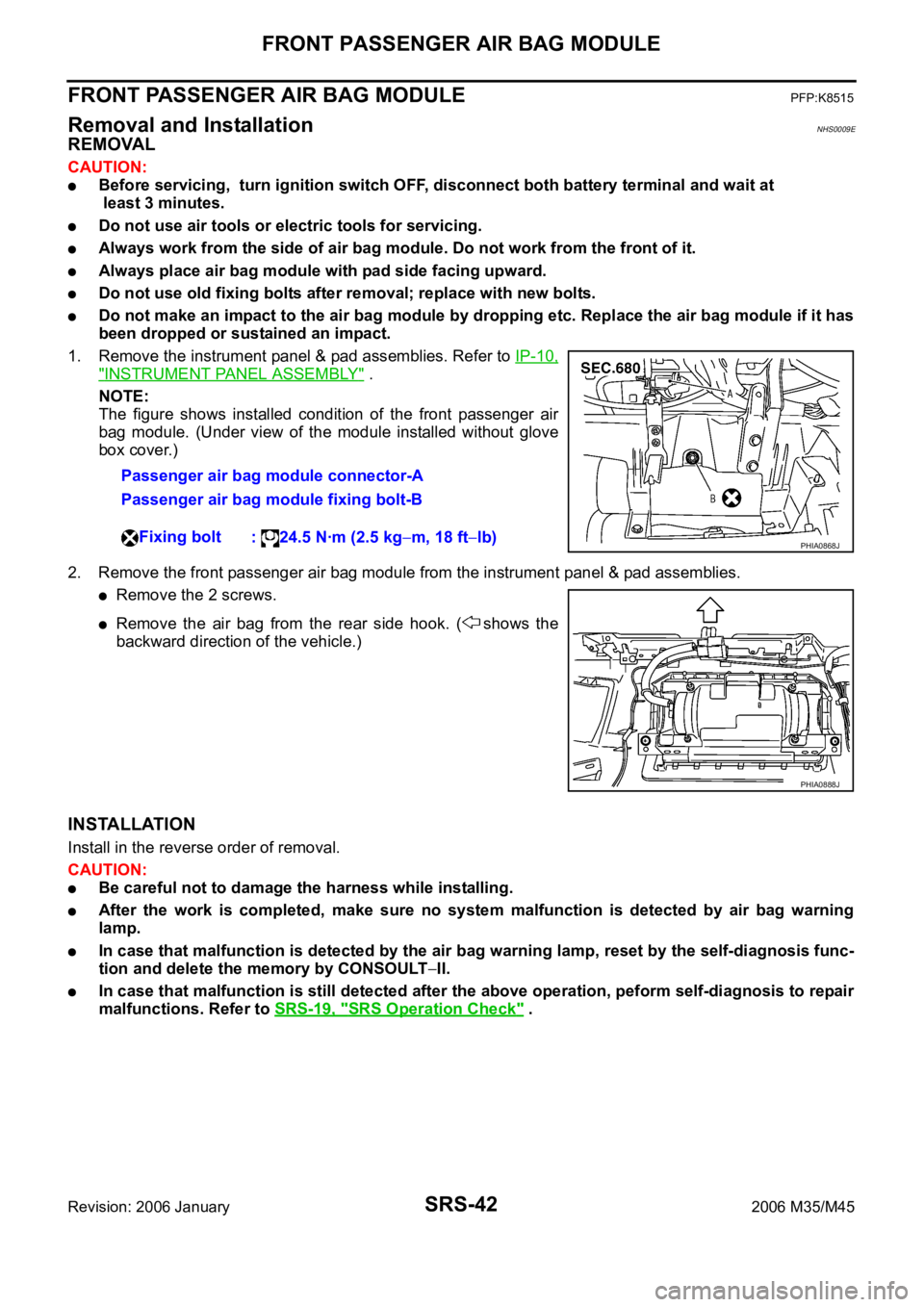
1. Remove the instrument panel & pad assemblies. Refer to IP-10,
"INSTRUMENT PANEL ASSEMBLY" .
NOTE:
The figure shows installed condition of the front passenger air
bag module. (Under view of the module installed without glove
box cover.)
2. Remove the front passenger air bag module from the instrument panel & pad assemblies.
Remove the 2 screws.
Remove the air bag from the rear side hook. ( shows the
backward direction of the vehicle.)
INSTALLATION
Install in the reverse order of removal.
CAUTION:
Be careful not to damage the harness while installing.
After the work is completed, make sure no system malfunction is detected by air bag warning
lamp.
In case that malfunction is detected by the air bag warning lamp, reset by the self-diagnosis func-
tion and delete the memory by CONSOULT
II.
In case that malfunction is still detected after the above operation, peform self-diagnosis to repair
malfunctions. Refer to SRS-19, "
SRS Operation Check" . Passenger air bag module connector-A
Passenger air bag module fixing bolt-B
Fixing bolt
: 24.5 Nꞏm (2.5 kg
m, 18 ftlb)PHIA0868J
PHIA0888J