height adjustment INFINITI M35 2006 Factory Owner's Manual
[x] Cancel search | Manufacturer: INFINITI, Model Year: 2006, Model line: M35, Model: INFINITI M35 2006Pages: 5621, PDF Size: 65.56 MB
Page 4611 of 5621

LT-184
ACTIVE AFS
Revision: 2006 January2006 M35/M45
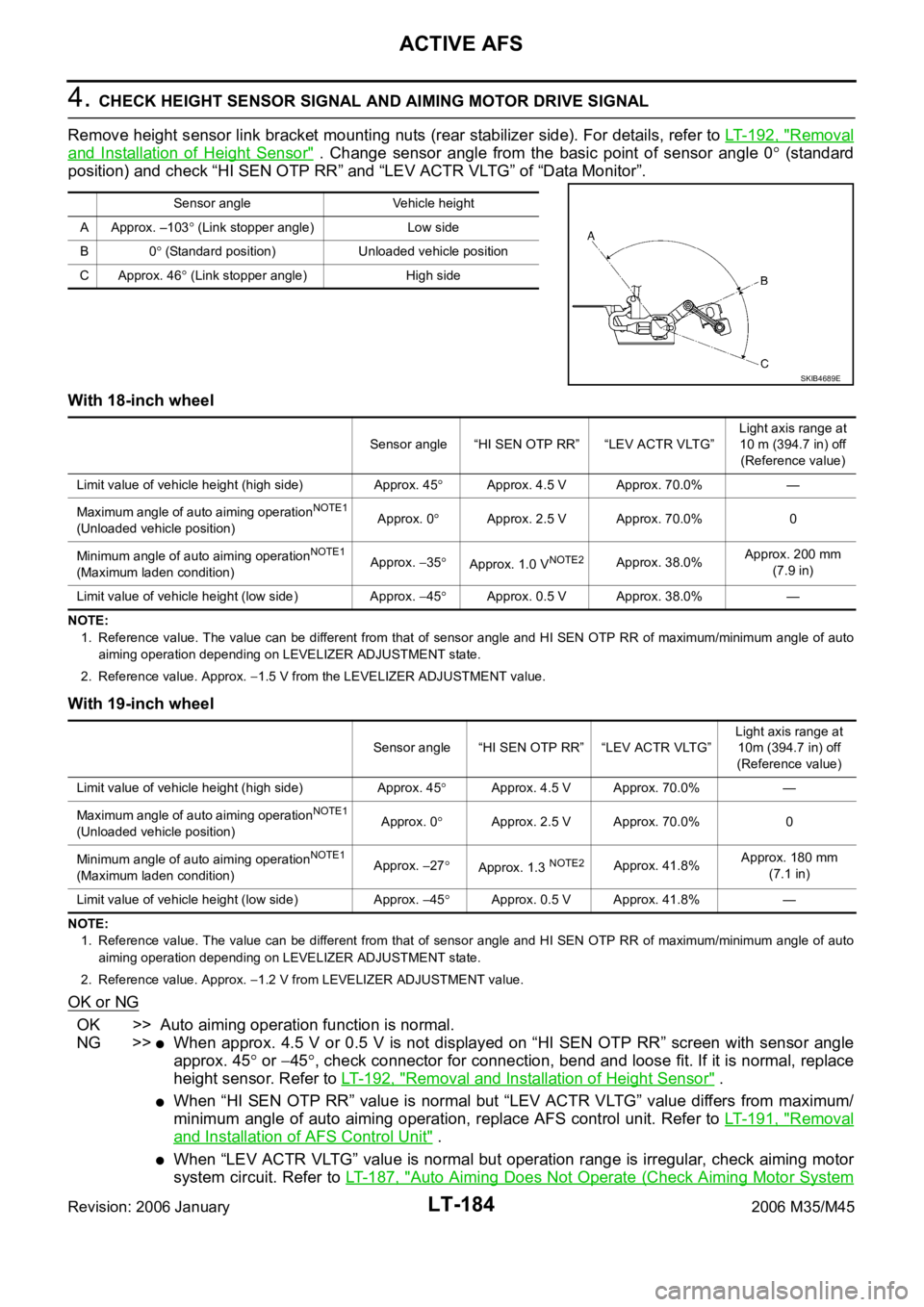
4. CHECK HEIGHT SENSOR SIGNAL AND AIMING MOTOR DRIVE SIGNAL
Remove height sensor link bracket mounting nuts (rear stabilizer side). For details, refer to LT- 1 9 2 , "
Removal
and Installation of Height Sensor" . Change sensor angle from the basic point of sensor angle 0 (standard
position) and check “HI SEN OTP RR” and “LEV ACTR VLTG” of “Data Monitor”.
With 18-inch wheel
NOTE:
1. Reference value. The value can be different from that of sensor angle and HI SEN OTP RR of maximum/minimum angle of auto
aiming operation depending on LEVELIZER ADJUSTMENT state.
2. Reference value. Approx.
1.5 V from the LEVELIZER ADJUSTMENT value.
With 19-inch wheel
NOTE:
1. Reference value. The value can be different from that of sensor angle and HI SEN OTP RR of maximum/minimum angle of auto
aiming operation depending on LEVELIZER ADJUSTMENT state.
2. Reference value. Approx.
1.2 V from LEVELIZER ADJUSTMENT value.
OK or NG
OK >> Auto aiming operation function is normal.
NG >>
When approx. 4.5 V or 0.5 V is not displayed on “HI SEN OTP RR” screen with sensor angle
approx. 45
or 45, check connector for connection, bend and loose fit. If it is normal, replace
height sensor. Refer to LT- 1 9 2 , "
Removal and Installation of Height Sensor" .
When “HI SEN OTP RR” value is normal but “LEV ACTR VLTG” value differs from maximum/
minimum angle of auto aiming operation, replace AFS control unit. Refer to LT- 1 9 1 , "
Removal
and Installation of AFS Control Unit" .
When “LEV ACTR VLTG” value is normal but operation range is irregular, check aiming motor
system circuit. Refer to LT- 1 8 7 , "
Auto Aiming Does Not Operate (Check Aiming Motor System
Sensor angle Vehicle height
A Approx. –103
(Link stopper angle) Low side
B0
(Standard position) Unloaded vehicle position
C Approx. 46
(Link stopper angle) High side
SKIB4689E
Sensor angle “HI SEN OTP RR” “LEV ACTR VLTG”Light axis range at
10 m (394.7 in) off
(Reference value)
Limit value of vehicle height (high side) Approx. 45
Approx. 4.5 V Approx. 70.0% —
Maximum angle of auto aiming operation
NOTE1
(Unloaded vehicle position)Approx. 0Approx. 2.5 V Approx. 70.0% 0
Minimum angle of auto aiming operation
NOTE1
(Maximum laden condition)Approx. 35Approx. 1.0 VNOTE2Approx. 38.0%Approx. 200 mm
(7.9 in)
Limit value of vehicle height (low side) Approx.
45Approx. 0.5 V Approx. 38.0% —
Sensor angle “HI SEN OTP RR” “LEV ACTR VLTG”Light axis range at
10m (394.7 in) off
(Reference value)
Limit value of vehicle height (high side) Approx. 45
Approx. 4.5 V Approx. 70.0% —
Maximum angle of auto aiming operation
NOTE1
(Unloaded vehicle position)Approx. 0Approx. 2.5 V Approx. 70.0% 0
Minimum angle of auto aiming operation
NOTE1
(Maximum laden condition)Approx. 27Approx. 1.3 NOTE2Approx. 41.8%Approx. 180 mm
(7.1 in)
Limit value of vehicle height (low side) Approx.
45Approx. 0.5 V Approx. 41.8% —
Page 4619 of 5621

LT-192
ACTIVE AFS
Revision: 2006 January2006 M35/M45
Removal and Installation of Height SensorNKS003R1
REMOVAL
1. Disconnect height sensor connector.
2. Remove height sensor link bracket mounting nuts (1). (rear stabilizer side)
CAUTION:
Never remove from the installation nut of height sensor link bracket (height sensor link side).
3. Remove bolts (2), and remove height sensor.
: Nꞏm (kg-m, ft-lb)
INSTALLATION
Installation is the reverse order of removal.
CAUTION:
Tighten the bracket while pushing onto rear stabilizer when installing the installation nut of height
sensor link bracket (stabilizer side).
NOTE:
Adjust levelizer when replacing height sensor. For details, refer to LT- 1 5 3 , "
WORK SUPPORT (LEVELIZER
ADJUSTMENT)" .
SKIB4211E
Page 5611 of 5621

WW-44
FRONT WIPER AND WASHER SYSTEM
Revision: 2006 January2006 M35/M45
DISASSEMBLY
1. Remove wiper linkage from wiper motor and motor frame.
2. Remove wiper motor mounting bolts (3), and remove wiper motor from wiper frame.
CAUTION:
Be careful not to bend linkage and not to damage the resin part of ball joint when removing wiper link-
age.
ASSEMBLY
1. Connect wiper motor connector. Turn wiper switch ON to operate wiper motor, and then turn wiper switch
OFF (auto stop).
2. Disconnect wiper motor connector.
3. Install wiper motor to wiper frame.
4. Install wiper linkage to wiper frame and wiper motor.
CAUTION:
Never drop the wiper motor or cause it to contact other parts.
Check grease conditions of the motor arm and wiper linkage joint (at retainer). Apply grease if
necessary.
Washer Nozzle AdjustmentNKS003X1
Adjust spray positions to match the positions shown in the figure.
Unit: mm (in)
Insert a needle or suitable tool into the nozzle hole and move up/
down and left/right to adjust the spray position.Wiper motor mounting bolts : 4.5 Nꞏm (0.46 kg-m, 40 in-lb)
Spray position h (height) l (width)Diameter
(spray point area)
A 167.1 (6.58) 491.9 (19.37) 130.8 (5.15)
B 271.4 (10.69) 304.6 (11.99) 150 (5.91)
C 119.7 (4.71) 175.6 (6.91) 130 (5.12)
D 160.5 (63.2) 60.1 (2.37) 120 (4.72)
E 266.6 (10.50) 292.6 (11.52) 140 (5.51)
F 118.8 (4.68) 485.0 (19.09) 85 (3.35)
SKIB4232E
SKIB4250E