fuel system INFINITI M35 2006 Factory Service Manual
[x] Cancel search | Manufacturer: INFINITI, Model Year: 2006, Model line: M35, Model: INFINITI M35 2006Pages: 5621, PDF Size: 65.56 MB
Page 5153 of 5621

SC-16
STARTING SYSTEM
Revision: 2006 January2006 M35/M45
DIAGNOSTIC PROCEDURE 2
Check “S” Connector Circuit
CAUTION:
Perform diagnosis under the condition that engine cannot start by the following procedure.
1. Remove fuel pump fuse.
2. Crank or start the engine (where possible) until the fuel pressure is released.
1. CHECK “S” CONNECTOR CIRCUIT
1. Turn ignition switch OFF.
2. Disconnect starter motor connector.
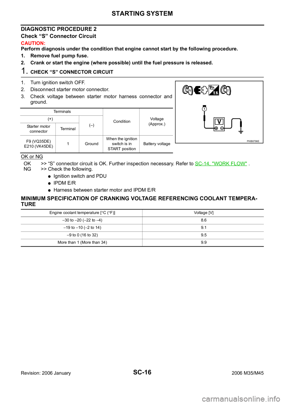
3. Check voltage between starter motor harness connector and
ground.
OK or NG
OK >> “S” connector circuit is OK. Further inspection necessary. Refer to SC-14, "WORK FLOW" .
NG >> Check the following.
Ignition switch and PDU
IPDM E/R
Harness between starter motor and IPDM E/R
MINIMUM SPECIFICATION OF CRANKING VOLTAGE REFERENCING COOLANT TEMPERA-
TURE
Te r m i n a l s
ConditionVoltage
(Approx.) (+)
(–)
Starter motor
connectorTe r m i n a l
F9 (VQ35DE)
E210 (VK45DE)1 GroundWhen the ignition
switch is in
START positionBattery voltage
PKIB8796E
Engine coolant temperature [C (F)] Voltage [V]
30 to 20 (22 to 4) 8.6
19 to 10 (2 to 14) 9.1
9 to 0 (16 to 32) 9.5
More than 1 (More than 34) 9.9
Page 5161 of 5621

SC-24
CHARGING SYSTEM
Revision: 2006 January2006 M35/M45
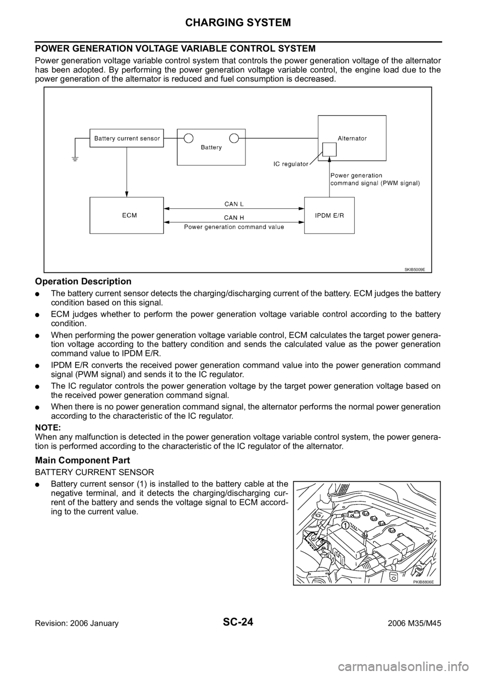
POWER GENERATION VOLTAGE VARIABLE CONTROL SYSTEM
Power generation voltage variable control system that controls the power generation voltage of the alternator
has been adopted. By performing the power generation voltage variable control, the engine load due to the
power generation of the alternator is reduced and fuel consumption is decreased.
Operation Description
The battery current sensor detects the charging/discharging current of the battery. ECM judges the battery
condition based on this signal.
ECM judges whether to perform the power generation voltage variable control according to the battery
condition.
When performing the power generation voltage variable control, ECM calculates the target power genera-
tion voltage according to the battery condition and sends the calculated value as the power generation
command value to IPDM E/R.
IPDM E/R converts the received power generation command value into the power generation command
signal (PWM signal) and sends it to the IC regulator.
The IC regulator controls the power generation voltage by the target power generation voltage based on
the received power generation command signal.
When there is no power generation command signal, the alternator performs the normal power generation
according to the characteristic of the IC regulator.
NOTE:
When any malfunction is detected in the power generation voltage variable control system, the power genera-
tion is performed according to the characteristic of the IC regulator of the alternator.
Main Component Part
BATTERY CURRENT SENSOR
Battery current sensor (1) is installed to the battery cable at the
negative terminal, and it detects the charging/discharging cur-
rent of the battery and sends the voltage signal to ECM accord-
ing to the current value.
SKIB5009E
PKIB8806E
Page 5475 of 5621

TF-10
AWD SYSTEM
Revision: 2006 January2006 M35/M45
AWD SYSTEMPFP:41650
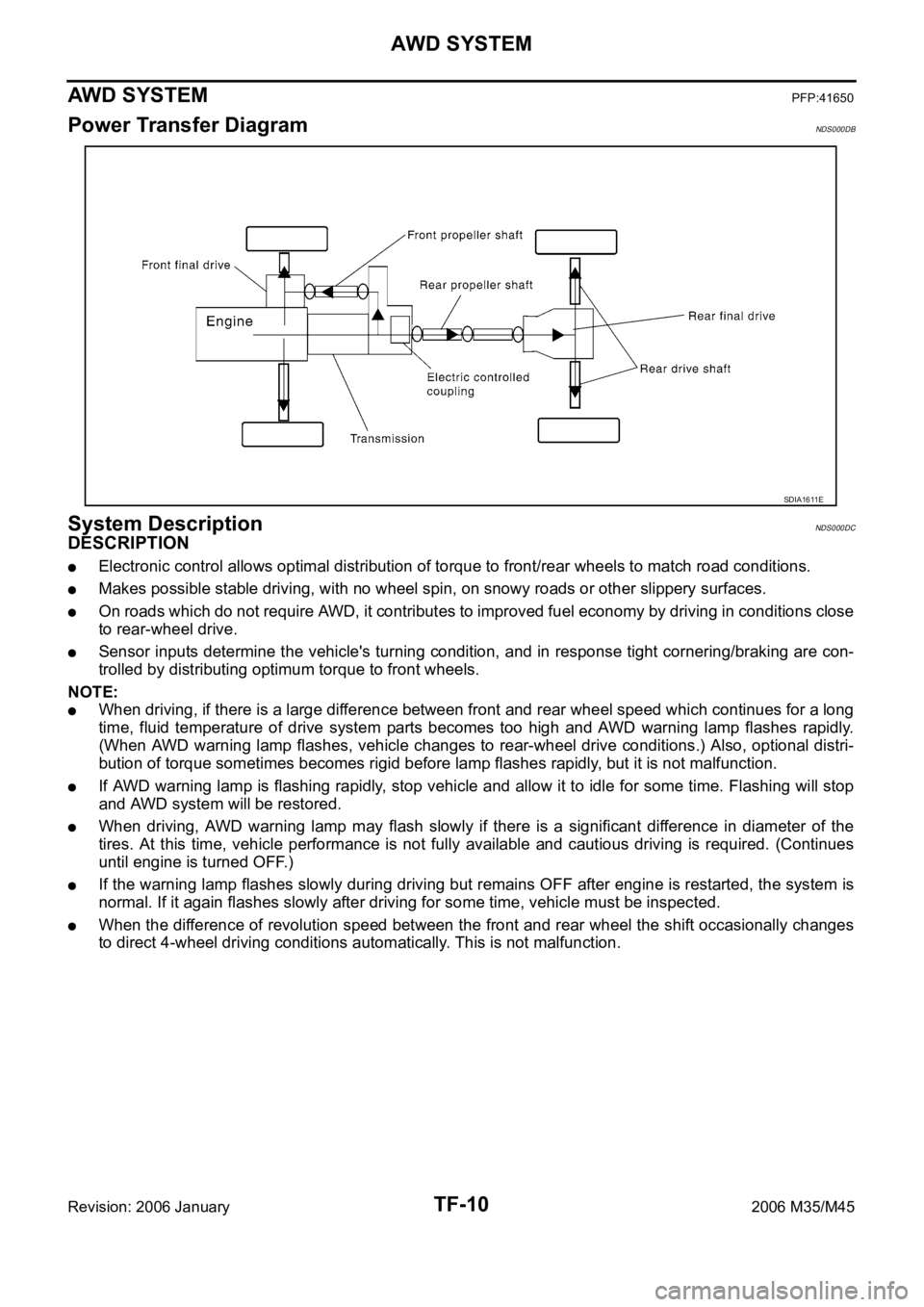
Power Transfer DiagramNDS000DB
System DescriptionNDS000DC
DESCRIPTION
Electronic control allows optimal distribution of torque to front/rear wheels to match road conditions.
Makes possible stable driving, with no wheel spin, on snowy roads or other slippery surfaces.
On roads which do not require AWD, it contributes to improved fuel economy by driving in conditions close
to rear-wheel drive.
Sensor inputs determine the vehicle's turning condition, and in response tight cornering/braking are con-
trolled by distributing optimum torque to front wheels.
NOTE:
When driving, if there is a large difference between front and rear wheel speed which continues for a long
time, fluid temperature of drive system parts becomes too high and AWD warning lamp flashes rapidly.
(When AWD warning lamp flashes, vehicle changes to rear-wheel drive conditions.) Also, optional distri-
bution of torque sometimes becomes rigid before lamp flashes rapidly, but it is not malfunction.
If AWD warning lamp is flashing rapidly, stop vehicle and allow it to idle for some time. Flashing will stop
and AWD system will be restored.
When driving, AWD warning lamp may flash slowly if there is a significant difference in diameter of the
tires. At this time, vehicle performance is not fully available and cautious driving is required. (Continues
until engine is turned OFF.)
If the warning lamp flashes slowly during driving but remains OFF after engine is restarted, the system is
normal. If it again flashes slowly after driving for some time, vehicle must be inspected.
When the difference of revolution speed between the front and rear wheel the shift occasionally changes
to direct 4-wheel driving conditions automatically. This is not malfunction.
SDIA1611E