ABS INFINITI M35 2006 Factory Service Manual
[x] Cancel search | Manufacturer: INFINITI, Model Year: 2006, Model line: M35, Model: INFINITI M35 2006Pages: 5621, PDF Size: 65.56 MB
Page 4753 of 5621
![INFINITI M35 2006 Factory Service Manual LU-10
[VQ35DE]
OIL FILTER
Revision: 2006 January2006 M35/M45
OIL FILTERPFP:15208
Removal and InstallationNBS004PY
REMOVAL
1. Remove front engine undercover with power tool.
2. Using oil filter wrench INFINITI M35 2006 Factory Service Manual LU-10
[VQ35DE]
OIL FILTER
Revision: 2006 January2006 M35/M45
OIL FILTERPFP:15208
Removal and InstallationNBS004PY
REMOVAL
1. Remove front engine undercover with power tool.
2. Using oil filter wrench](/img/42/57023/w960_57023-4752.png)
LU-10
[VQ35DE]
OIL FILTER
Revision: 2006 January2006 M35/M45
OIL FILTERPFP:15208
Removal and InstallationNBS004PY
REMOVAL
1. Remove front engine undercover with power tool.
2. Using oil filter wrench (SST), remove oil filter.
CAUTION:
Oil filter is provided with relief valve. Use Genuine Nissan
Oil Filter or equivalent.
Be careful not to get burned when engine and engine oil
may be hot.
When removing, prepare a shop cloth to absorb any
engine oil leakage or spillage.
Do not allow engine oil to adhere to drive belts.
Completely wipe off any engine oil that adheres to engine
and vehicle.
INSTALLATION
1. Remove foreign materials adhering to oil filter installation surface.
2. Apply engine oil to the oil seal contact surface of new oil filter.
3. Screw oil filter manually until it touches the installation surface,
then tighten it by 2/3 turn. Or tighten to the specification.
INSPECTION AFTER INSTALLATION
1. Check the engine oil level. Refer to LU-7, "ENGINE OIL" .
2. Start the engine, and check there is no leak of engine oil.
SBIA0454E
SBIA0455E
SMA010
Oil filter:
: 17.7 Nꞏm (1.8 kg-m, 13 ft-lb)
SMA229B
Page 4772 of 5621
![INFINITI M35 2006 Factory Service Manual OIL FILTER
LU-29
[VK45DE]
C
D
E
F
G
H
I
J
K
L
MA
LU
Revision: 2006 January2006 M35/M45
OIL FILTERPFP:15208
Removal and InstallationNBS004QE
REMOVAL
1. Remove front engine undercover with power tool.
2 INFINITI M35 2006 Factory Service Manual OIL FILTER
LU-29
[VK45DE]
C
D
E
F
G
H
I
J
K
L
MA
LU
Revision: 2006 January2006 M35/M45
OIL FILTERPFP:15208
Removal and InstallationNBS004QE
REMOVAL
1. Remove front engine undercover with power tool.
2](/img/42/57023/w960_57023-4771.png)
OIL FILTER
LU-29
[VK45DE]
C
D
E
F
G
H
I
J
K
L
MA
LU
Revision: 2006 January2006 M35/M45
OIL FILTERPFP:15208
Removal and InstallationNBS004QE
REMOVAL
1. Remove front engine undercover with power tool.
2. Using the oil filter wrench (SST), remove the oil filter.
CAUTION:
Oil filter is provided with relief valve. Use Genuine Nissan
Oil Filter or equivalent.
Be careful not to get burned when engine and engine oil
may be hot.
When removing, prepare a shop cloth to absorb any
engine oil leakage or spillage.
Do not allow engine oil to adhere to drive belts.
Completely wipe off any engine oil that adhere to engine
and vehicle.
INSTALLATION
1. Remove foreign materials adhering to oil filter installation surface.
2. Apply new engine oil to the oil seal circumference of the new oil
filter.
3. Screw oil filter manually until it touches the installation surface,
then tighten it by 2/3 turn. Or tighten to specification.
INSPECTION AFTER INSTALLATION
1. Check the engine oil level. Refer to LU-26, "ENGINE OIL" .
2. Start engine, and check there is no leaks of engine oil.
3. Stop engine and wait for 15 minutes.
4. Check the engine oil level and adjust engine oil. Refer to LU-26, "
ENGINE OIL" .
PBIC1525E
SMA010
Oil filter:
:17.7 Nꞏm (1.8 kg-m, 13 ft-lb)
SMA229B
Page 4796 of 5621

ENGINE MAINTENANCE (VQ35DE ENGINE)
MA-19
C
D
E
F
G
H
I
J
K
MA
B
MA
Revision: 2006 January2006 M35/M45
CAUTION:
When filling engine oil, do not pull out oil level gauge.
The refill capacity depends on the engine oil temperature and drain time. Use these specifica-
tions for reference only.
Always use oil level gauge to determine the proper amount of engine oil in engine.
8. Warm up the engine and check area around drain plug and oil filter for engine oil leakage.
9. Stop the engine and wait for 10 minutes.
10. Check the engine oil level.
Changing Oil FilterNLS0007N
REMOVAL
WAR NING :
Be careful not to get burned when the engine and engine oil may be hot.
1. Remove front engine undercover with power tool.
2. Using oil filter wrench [SST], remove oil filter.
CAUTION:
Oil filter is provided with relief valve. Use Genuine Nissan
Oil Filter or equivalent.
When removing, prepare a shop cloth to absorb any
engine oil leakage or spillage.
Do not allow engine oil to adhere to drive belts.
Completely wipe off any engine oil that adheres to engine
and vehicle.
INSTALLATION
1. Remove foreign materials adhering to oil filter installation surface.
PBIC0249E
SBIA0454E
SBIA0455E
Page 4803 of 5621

MA-26
ENGINE MAINTENANCE (VK45DE ENGINE)
Revision: 2006 January2006 M35/M45
7. Refill with new engine oil.
Engine oil specification and viscosity:
Refer to MA-12, "
RECOMMENDED FLUIDS AND LUBRICANTS" .
Engine oil capacity (Approximate):
Unit: (US qt, Imp qt)
CAUTION:
The refill capacity depends on the engine oil temperature and drain time. Use these specifica-
tions for reference only.
Always use oil level gauge to determine the proper amount of engine oil in the engine.
8. Warm up engine and check area around drain plug and oil filter for oil leakage.
9. Stop engine and wait for 15 minutes.
10. Check the engine oil level.
Changing Oil FilterNLS0007W
REMOVAL
WAR NING :
Be careful not to get burned when the engine and engine oil may be hot.
1. Remove front engine undercover with power tool.
2. Using the oil filter wrench (SST), remove the oil filter.
CAUTION:
Oil filter is provided with relief valve. Use Genuine Nissan
Oil Filter or equivalent.
When removing, prepare a shop cloth to absorb any
engine oil leakage or spillage.
Do not allow engine oil to adhere to drive belts.
Completely wipe off any engine oil that adhere to engine
and vehicle.
INSTALLATION
1. Remove foreign materials adhering to oil filter installation surface.
2. Apply new engine oil to the oil seal circumference of the new oil
filter.
Drain and refillWith oil filter change 5.5 (5-3/4, 4-7/8)
without oil filter change 4.9 (5-1/8, 4-1/4)
Dry engine (engine overhaul) 6.7 (7-1/8, 5-7/8)
PBIC0801E
PBIC1525E
SMA010
Page 4814 of 5621
CHASSIS AND BODY MAINTENANCE
MA-37
C
D
E
F
G
H
I
J
K
MA
B
MA
Revision: 2006 January2006 M35/M45
Checking Power Steering Fluid and LinesNLS0008E
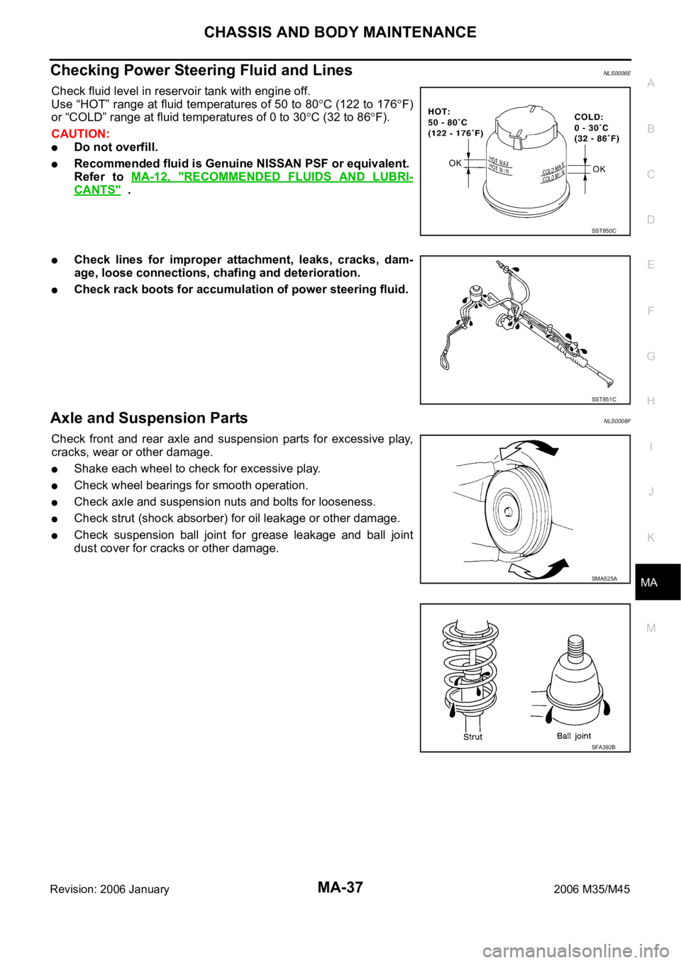
Check fluid level in reservoir tank with engine off.
Use “HOT” range at fluid temperatures of 50 to 80
C (122 to 176F)
or “COLD” range at fluid temperatures of 0 to 30
C (32 to 86F).
CAUTION:
Do not overfill.
Recommended fluid is Genuine NISSAN PSF or equivalent.
Refer to MA-12, "
RECOMMENDED FLUIDS AND LUBRI-
CANTS" .
Check lines for improper attachment, leaks, cracks, dam-
age, loose connections, chafing and deterioration.
Check rack boots for accumulation of power steering fluid.
Axle and Suspension PartsNLS0008F
Check front and rear axle and suspension parts for excessive play,
cracks, wear or other damage.
Shake each wheel to check for excessive play.
Check wheel bearings for smooth operation.
Check axle and suspension nuts and bolts for looseness.
Check strut (shock absorber) for oil leakage or other damage.
Check suspension ball joint for grease leakage and ball joint
dust cover for cracks or other damage.
SST850C
SST851C
SMA525A
SFA392B
Page 5005 of 5621
RAX-6
WHEEL HUB
Revision: 2006 January2006 M35/M45
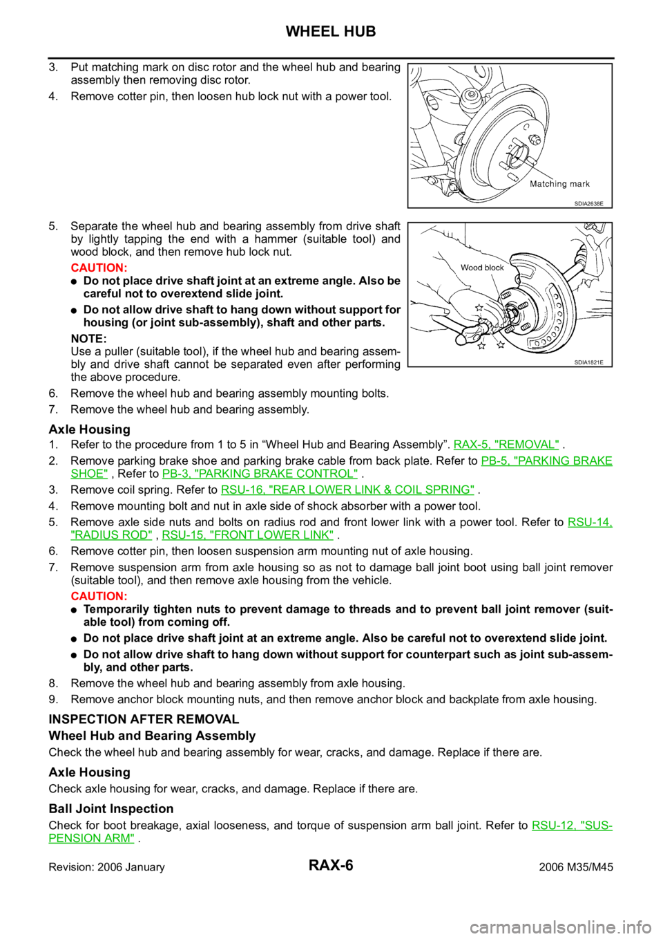
3. Put matching mark on disc rotor and the wheel hub and bearing
assembly then removing disc rotor.
4. Remove cotter pin, then loosen hub lock nut with a power tool.
5. Separate the wheel hub and bearing assembly from drive shaft
by lightly tapping the end with a hammer (suitable tool) and
wood block, and then remove hub lock nut.
CAUTION:
Do not place drive shaft joint at an extreme angle. Also be
careful not to overextend slide joint.
Do not allow drive shaft to hang down without support for
housing (or joint sub-assembly), shaft and other parts.
NOTE:
Use a puller (suitable tool), if the wheel hub and bearing assem-
bly and drive shaft cannot be separated even after performing
the above procedure.
6. Remove the wheel hub and bearing assembly mounting bolts.
7. Remove the wheel hub and bearing assembly.
Axle Housing
1. Refer to the procedure from 1 to 5 in “Wheel Hub and Bearing Assembly”. RAX-5, "REMOVAL" .
2. Remove parking brake shoe and parking brake cable from back plate. Refer to PB-5, "
PA R K I N G B R A K E
SHOE" , Refer to PB-3, "PARKING BRAKE CONTROL" .
3. Remove coil spring. Refer to RSU-16, "
REAR LOWER LINK & COIL SPRING" .
4. Remove mounting bolt and nut in axle side of shock absorber with a power tool.
5. Remove axle side nuts and bolts on radius rod and front lower link with a power tool. Refer to RSU-14,
"RADIUS ROD" , RSU-15, "FRONT LOWER LINK" .
6. Remove cotter pin, then loosen suspension arm mounting nut of axle housing.
7. Remove suspension arm from axle housing so as not to damage ball joint boot using ball joint remover
(suitable tool), and then remove axle housing from the vehicle.
CAUTION:
Temporarily tighten nuts to prevent damage to threads and to prevent ball joint remover (suit-
able tool) from coming off.
Do not place drive shaft joint at an extreme angle. Also be careful not to overextend slide joint.
Do not allow drive shaft to hang down without support for counterpart such as joint sub-assem-
bly, and other parts.
8. Remove the wheel hub and bearing assembly from axle housing.
9. Remove anchor block mounting nuts, and then remove anchor block and backplate from axle housing.
INSPECTION AFTER REMOVAL
Wheel Hub and Bearing Assembly
Check the wheel hub and bearing assembly for wear, cracks, and damage. Replace if there are.
Axle Housing
Check axle housing for wear, cracks, and damage. Replace if there are.
Ball Joint Inspection
Check for boot breakage, axial looseness, and torque of suspension arm ball joint. Refer to RSU-12, "SUS-
PENSION ARM" .
SDIA2638E
SDIA1821E
Page 5082 of 5621
RSU-1
REAR SUSPENSION
E SUSPENSION
CONTENTS
C
D
F
G
H
I
J
K
L
M
SECTION RSU
A
B
RSU
Revision: 2006 January2006 M35/M45
REAR SUSPENSION
PRECAUTIONS .......................................................... 2
Precautions .............................................................. 2
PREPARATION ........................................................... 3
Special Service Tools [SST] ..................................... 3
Commercial Service Tools ........................................ 3
NOISE, VIBRATION AND HARSHNESS (NVH)
TROUBLESHOOTING ................................................ 4
NVH Troubleshooting Chart ..................................... 4
REAR SUSPENSION ASSEMBLY ............................. 5
On-Vehicle Inspection and Service .......................... 5
SUSPENSION ARM BALL JOINT AXIAL END
PLAY INSPECTION .............................................. 5
SHOCK ABSORBER INSPECTION ..................... 5
Wheel Alignment Inspection ..................................... 5
DESCRIPTION ...................................................... 5
PRELIMINARY INSPECTION ............................... 5
GENERAL INFORMATION AND RECOMMEN-
DATIONS .............................................................. 5
THE ALIGNMENT PROCESS .............................. 6
CAMBER INSPECTION ........................................ 6
TOE-IN .................................................................. 6
Components ............................................................. 7
Removal and Installation .......................................... 8
REMOVAL ........................................................
..... 8
INSTALLATION ..................................................... 8
SHOCK ABSORBER ................................................ 10
Removal and Installation ........................................ 10
REMOVAL ........................................................
... 10
INSPECTION AFTER REMOVAL ....................... 10
INSTALLATION ................................................... 10
Disassembly and Assembly ................................... 10
DISASSEMBLY ................................................... 10
INSPECTION AFTER DISASSEMBLY ............... 10
ASSEMBLY .......................................................... 11SUSPENSION ARM .................................................. 12
Removal and Installation ........................................ 12
REMOVAL ........................................................
... 12
INSPECTION AFTER REMOVAL ....................... 12
INSTALLATION ................................................... 13
RADIUS ROD ............................................................ 14
Removal and Installation ........................................ 14
REMOVAL ........................................................
... 14
INSPECTION AFTER REMOVAL ....................... 14
INSTALLATION ................................................... 14
FRONT LOWER LINK .............................................. 15
Removal and Installation ........................................ 15
REMOVAL ........................................................
... 15
INSPECTION AFTER REMOVAL ....................... 15
INSTALLATION ................................................... 15
REAR LOWER LINK & COIL SPRING ..................
... 16
Removal and Installation ........................................ 16
REMOVAL ........................................................
... 16
INSPECTION AFTER REMOVAL ....................... 16
INSTALLATION ................................................... 16
STABILIZER BAR ..................................................... 17
Removal and Installation ........................................ 17
REMOVAL ........................................................
... 17
INSPECTION AFTER REMOVAL ....................... 17
INSTALLATION ................................................... 17
SERVICE DATA ........................................................ 18
Wheel Alignment (Unladen)* .................................. 18
Ball Joint ................................................................. 18
Wheelarch Height (Unladen*) ................................. 18
Page 5085 of 5621

RSU-4
NOISE, VIBRATION AND HARSHNESS (NVH) TROUBLESHOOTING
Revision: 2006 January2006 M35/M45
NOISE, VIBRATION AND HARSHNESS (NVH) TROUBLESHOOTINGPFP:00003
NVH Troubleshooting ChartNES000J5
Use chart below to help you find the cause of the symptom. If necessary, repair or replace these parts.
: ApplicableReference page
RSU-7RSU-10
—
—
—
RSU-7RSU-5RSU-17
NVH in PR section.
NVH in RFD section.
NVH in RAX and RSU sections.
NVH in WT section.
NVH in WT section.
NVH in RAX section.
NVH in BR section.
NVH in PS section.
Possible cause and SUSPECTED PARTS
Improper installation, looseness
Shock absorber deformation, damage or deflection
Bushing or mounting deterioration
Parts interference
Spring fatigue
Suspension looseness
Incorrect wheel alignment
Stabilizer bar fatigue
PROPELLER SHAFT
DIFFERENTIAL
REAR AXLE AND REAR SUSPENSION
TIRES
ROAD WHEELS
DRIVE SHAFT
BRAKES
STEERING
Symptom REAR SUSPENSIONNoise
Shake
Vibration
Shimmy
Judder
Poor quality ride or
handling
Page 5086 of 5621
REAR SUSPENSION ASSEMBLY
RSU-5
C
D
F
G
H
I
J
K
L
MA
B
RSU
Revision: 2006 January2006 M35/M45
REAR SUSPENSION ASSEMBLYPFP:55020
On-Vehicle Inspection and ServiceNES000J6
Make sure the mounting conditions (looseness, back lash) of each component and component conditions
(wear, damage) are normal.
SUSPENSION ARM BALL JOINT AXIAL END PLAY INSPECTION
Measure axial end play by placing and moving up/down with an iron pry bar or something similar between sus-
pension arm and axle.
CAUTION:
Be careful not to damage ball joint boot.
SHOCK ABSORBER INSPECTION
Check shock absorber for oil leakage, damage and replace if malfunction is detected.
Wheel Alignment InspectionNES000J7
DESCRIPTION
Measure wheel alignment under unladen conditions.
NOTE:
“Unladen conditions” means that fuel, engine coolant, and lubricant are full. Spare tire, jack, hand tools and
mats in designated positions.
PRELIMINARY INSPECTION
Check the following:
1. Tires for improper air pressure and wear.
2. Road wheels for runout. Refer to WT-6, "
ROAD WHEEL" .
3. Wheel bearing axial end play. Refer to RAX-5, "
WHEEL BEARING INSPECTION" .
4. Ball joint axial end play of suspension arm. Refer to RSU-5, "
SUSPENSION ARM BALL JOINT AXIAL
END PLAY INSPECTION" .
5. Shock absorber operation.
6. Each mounting point of axle and suspension for looseness and deformation.
7. Each of front lower link, rear lower link, radius rod, rear suspension member, suspension arm and shock
absorber for cracks, deformation, and other damage.
8. Vehicle height (posture).
GENERAL INFORMATION AND RECOMMENDATIONS
A four-wheel thrust alignment should be performed.
–This type of alignment is recommended for any NISSAN/INFINITI vehicle.
–The four-wheel “thrust” process helps ensure that the vehicle is properly aligned and the steering wheel is
centered.
–The alignment rack itself should be capable of accepting any NISSAN/INFINITI vehicle.
–The rack should be checked to ensure that it is level.
Make sure the machine is properly calibrated.
–Your alignment equipment should be regularly calibrated in order to give correct information.
–Check with the manufacturer of your specific equipment for their recommended Service/Calibration
Schedule.Standard value
Axial end play : 0 mm (0 in)
Page 5089 of 5621
RSU-8
REAR SUSPENSION ASSEMBLY
Revision: 2006 January2006 M35/M45
Refer to GI section for symbol marks in the figure. Refer to GI-9, "HOW TO USE THIS MANUAL" .
Removal and InstallationNES000J9
REMOVAL
1. Remove tire with a power tool.
2. Remove brake caliper with a power tool. Hang it in a place where it will not interfere with work. Refer to
BR-29, "
REAR DISC BRAKE" .
CAUTION:
Do not depressing brake pedal while brake caliper is removed.
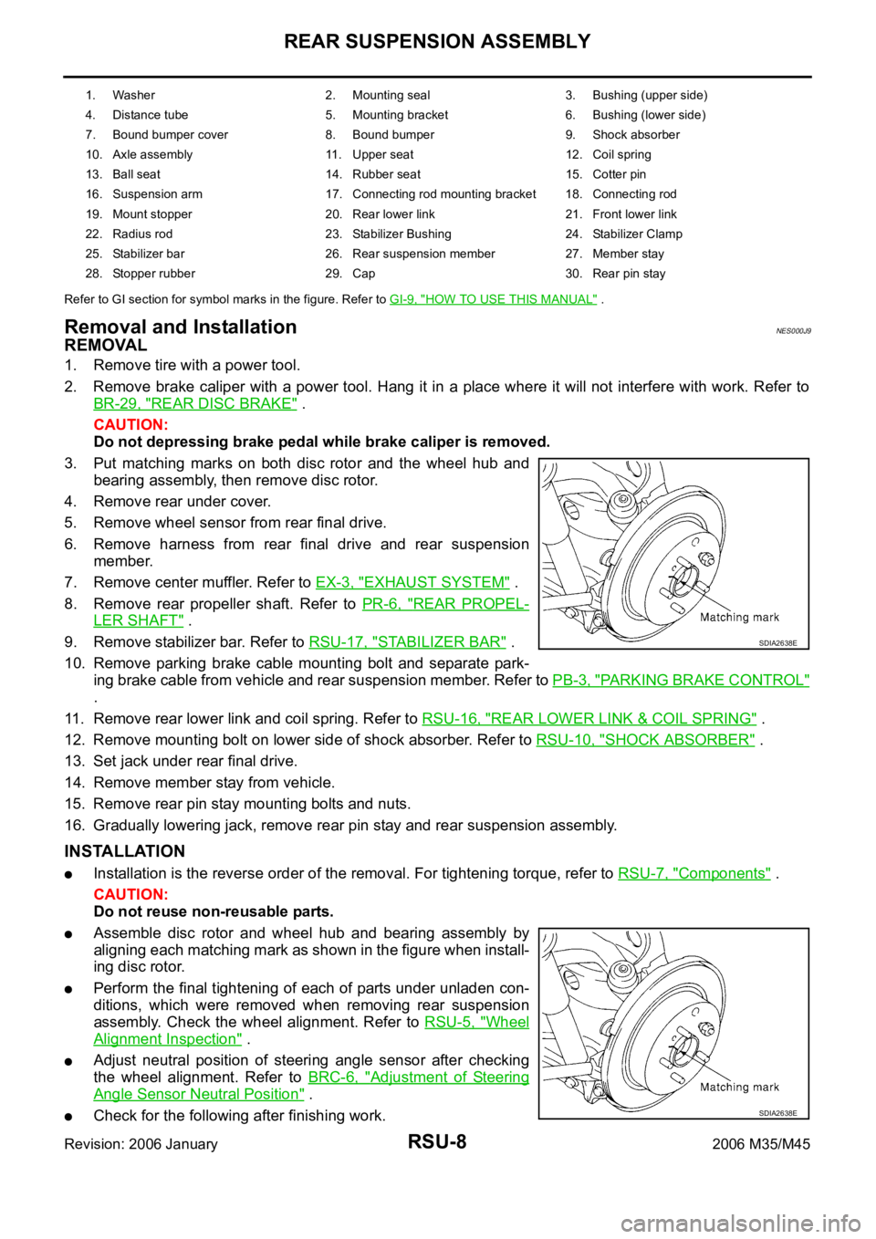
3. Put matching marks on both disc rotor and the wheel hub and
bearing assembly, then remove disc rotor.
4. Remove rear under cover.
5. Remove wheel sensor from rear final drive.
6. Remove harness from rear final drive and rear suspension
member.
7. Remove center muffler. Refer to EX-3, "
EXHAUST SYSTEM" .
8. Remove rear propeller shaft. Refer to PR-6, "
REAR PROPEL-
LER SHAFT" .
9. Remove stabilizer bar. Refer to RSU-17, "
STABILIZER BAR" .
10. Remove parking brake cable mounting bolt and separate park-
ing brake cable from vehicle and rear suspension member. Refer to PB-3, "
PARKING BRAKE CONTROL"
.
11. Remove rear lower link and coil spring. Refer to RSU-16, "
REAR LOWER LINK & COIL SPRING" .
12. Remove mounting bolt on lower side of shock absorber. Refer to RSU-10, "
SHOCK ABSORBER" .
13. Set jack under rear final drive.
14. Remove member stay from vehicle.
15. Remove rear pin stay mounting bolts and nuts.
16. Gradually lowering jack, remove rear pin stay and rear suspension assembly.
INSTALLATION
Installation is the reverse order of the removal. For tightening torque, refer to RSU-7, "Components" .
CAUTION:
Do not reuse non-reusable parts.
Assemble disc rotor and wheel hub and bearing assembly by
aligning each matching mark as shown in the figure when install-
ing disc rotor.
Perform the final tightening of each of parts under unladen con-
ditions, which were removed when removing rear suspension
assembly. Check the wheel alignment. Refer to RSU-5, "
Wheel
Alignment Inspection" .
Adjust neutral position of steering angle sensor after checking
the wheel alignment. Refer to BRC-6, "
Adjustment of Steering
Angle Sensor Neutral Position" .
Check for the following after finishing work.
1. Washer 2. Mounting seal 3. Bushing (upper side)
4. Distance tube 5. Mounting bracket 6. Bushing (lower side)
7. Bound bumper cover 8. Bound bumper 9. Shock absorber
10. Axle assembly 11. Upper seat 12. Coil spring
13. Ball seat 14. Rubber seat 15. Cotter pin
16. Suspension arm 17. Connecting rod mounting bracket 18. Connecting rod
19. Mount stopper 20. Rear lower link 21. Front lower link
22. Radius rod 23. Stabilizer Bushing 24. Stabilizer Clamp
25. Stabilizer bar 26. Rear suspension member 27. Member stay
28. Stopper rubber 29. Cap 30. Rear pin stay
SDIA2638E
SDIA2638E