ABS INFINITI M35 2006 Factory Service Manual
[x] Cancel search | Manufacturer: INFINITI, Model Year: 2006, Model line: M35, Model: INFINITI M35 2006Pages: 5621, PDF Size: 65.56 MB
Page 5091 of 5621

RSU-10
SHOCK ABSORBER
Revision: 2006 January2006 M35/M45
SHOCK ABSORBERPFP:56210
Removal and InstallationNES000JA
REMOVAL
1. Remove tires from vehicle with a power tool.
2. Set a jack under rear lower link to relieve the coil spring tension.
3. Remove shock absorber lower end bolt with a power tool.
4. Gradually lower the jack to remove it from rear lower link.
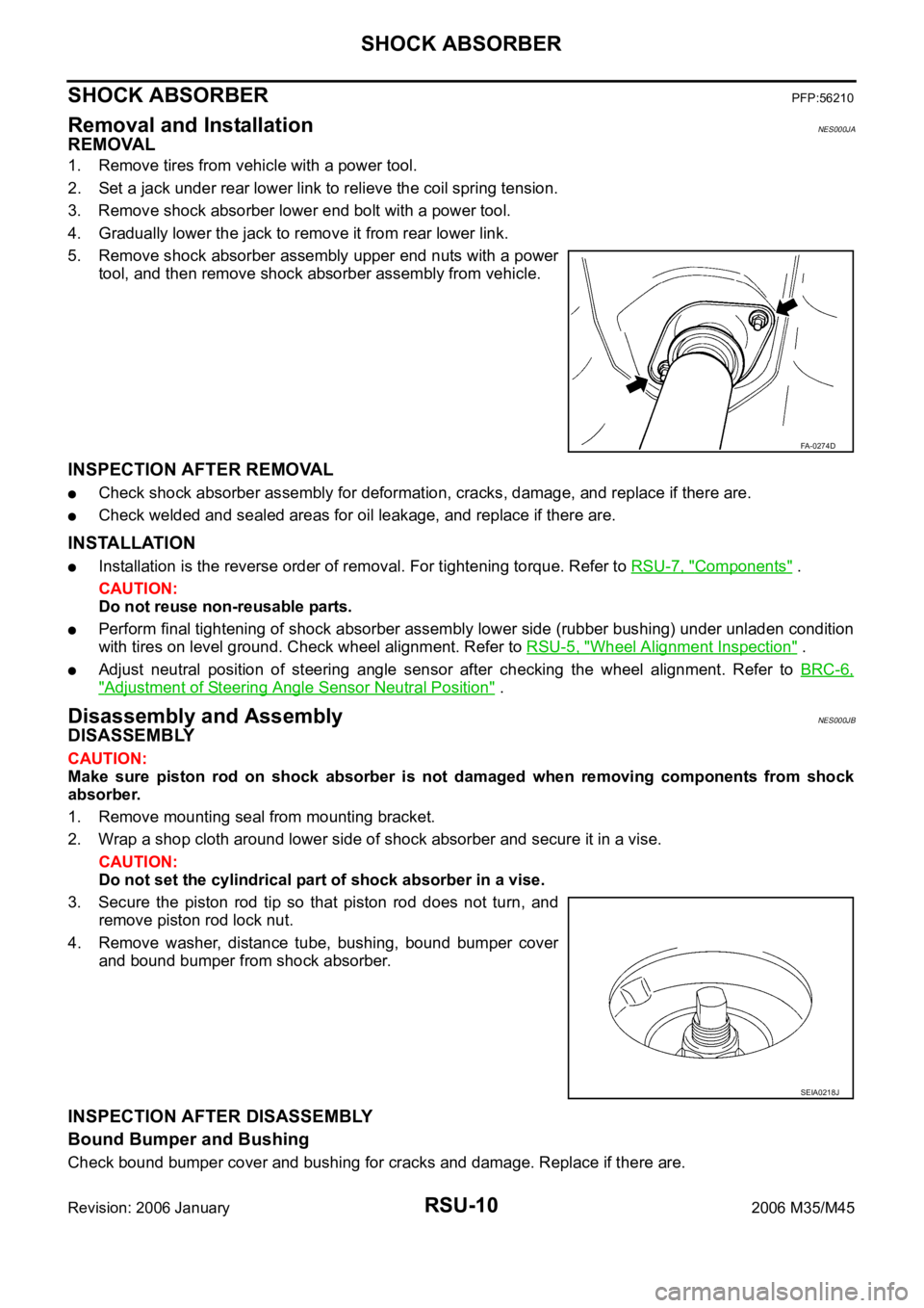
5. Remove shock absorber assembly upper end nuts with a power
tool, and then remove shock absorber assembly from vehicle.
INSPECTION AFTER REMOVAL
Check shock absorber assembly for deformation, cracks, damage, and replace if there are.
Check welded and sealed areas for oil leakage, and replace if there are.
INSTALLATION
Installation is the reverse order of removal. For tightening torque. Refer to RSU-7, "Components" .
CAUTION:
Do not reuse non-reusable parts.
Perform final tightening of shock absorber assembly lower side (rubber bushing) under unladen condition
with tires on level ground. Check wheel alignment. Refer to RSU-5, "
Wheel Alignment Inspection" .
Adjust neutral position of steering angle sensor after checking the wheel alignment. Refer to BRC-6,
"Adjustment of Steering Angle Sensor Neutral Position" .
Disassembly and AssemblyNES000JB
DISASSEMBLY
CAUTION:
Make sure piston rod on shock absorber is not damaged when removing components from shock
absorber.
1. Remove mounting seal from mounting bracket.
2. Wrap a shop cloth around lower side of shock absorber and secure it in a vise.
CAUTION:
Do not set the cylindrical part of shock absorber in a vise.
3. Secure the piston rod tip so that piston rod does not turn, and
remove piston rod lock nut.
4. Remove washer, distance tube, bushing, bound bumper cover
and bound bumper from shock absorber.
INSPECTION AFTER DISASSEMBLY
Bound Bumper and Bushing
Check bound bumper cover and bushing for cracks and damage. Replace if there are.
FA-0274D
SEIA0218J
Page 5092 of 5621

SHOCK ABSORBER
RSU-11
C
D
F
G
H
I
J
K
L
MA
B
RSU
Revision: 2006 January2006 M35/M45
Shock Absorber
Check the following:
Shock absorber for deformation, cracks, and other damage. Replace if there are.
Piston rod for damage, uneven wear, and distortion. Replace if there are.
ASSEMBLY
Installation is the reverse order of removal. For tightening torque. Refer to RSU-7, "Components" .
CAUTION:
Do not reuse non-reusable parts.
Make sure piston rod on shock absorber is not damaged when attaching components to shock absorber.
Page 5095 of 5621

RSU-14
RADIUS ROD
Revision: 2006 January2006 M35/M45
RADIUS RODPFP:55110
Removal and InstallationNES000JD
REMOVAL
1. Remove tire with a power tool.
2. Remove brake caliper with a power tool. Hang it in a place where it will not interfere with work. Refer to
BR-29, "
REAR DISC BRAKE" .
CAUTION:
Do not depressing brake pedal while brake caliper is removed.
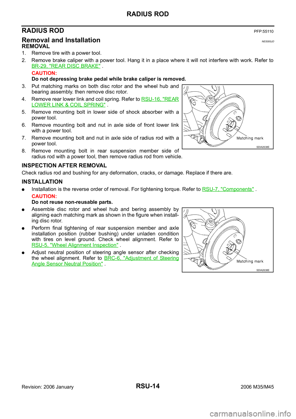
3. Put matching marks on both disc rotor and the wheel hub and
bearing assembly. then remove disc rotor.
4. Remove rear lower link and coil spring. Refer to RSU-16, "
REAR
LOWER LINK & COIL SPRING" .
5. Remove mounting bolt in lower side of shock absorber with a
power tool.
6. Remove mounting bolt and nut in axle side of front lower link
with a power tool.
7. Remove mounting bolt and nut in axle side of radius rod with a
power tool.
8. Remove mounting bolt in rear suspension member side of
radius rod with a power tool, then remove radius rod from vehicle.
INSPECTION AFTER REMOVAL
Check radius rod and bushing for any deformation, cracks, or damage. Replace if there are.
INSTALLATION
Installation is the reverse order of removal. For tightening torque. Refer to RSU-7, "Components" .
CAUTION:
Do not reuse non-reusable parts.
Assemble disc rotor and wheel hub and bering assembly by
aligning each matching mark as shown in the figure when install-
ing disc rotor.
Perform final tightening of rear suspension member and axle
installation position (rubber bushing) under unladen condition
with tires on level ground. Check wheel alignment. Refer to
RSU-5, "
Wheel Alignment Inspection" .
Adjust neutral position of steering angle sensor after checking
the wheel alignment. Refer to BRC-6, "
Adjustment of Steering
Angle Sensor Neutral Position" .
SDIA2638E
SDIA2638E
Page 5097 of 5621

RSU-16
REAR LOWER LINK & COIL SPRING
Revision: 2006 January2006 M35/M45
REAR LOWER LINK & COIL SPRINGPFP:551B0
Removal and InstallationNES000JF
REMOVAL
1. Remove tire with a power tool.
2. Set a jack under rear lower link to relieve the coil spring tension.
3. Loosen mounting bolt and nut of rear lower link inside of suspension member, and then remove mounting
bolt and nut inside of axle with a power tool.
4. Slowly lower jack, then remove upper seat, coil spring and rubber sheet from rear lower link.
5. Remove mounting bolt and nut inside of suspension member to remove rear lower link with a power tool.
INSPECTION AFTER REMOVAL
Check rear lower link, bushing and coil spring for deformation, cracks, and damage. Replace rear lower link
and coil spring if there are.
INSTALLATION
Installation is the reverse order of removal. For tightening torque. Refer to RSU-7, "Components" .
CAUTION:
Do not reuse non-reusable parts.
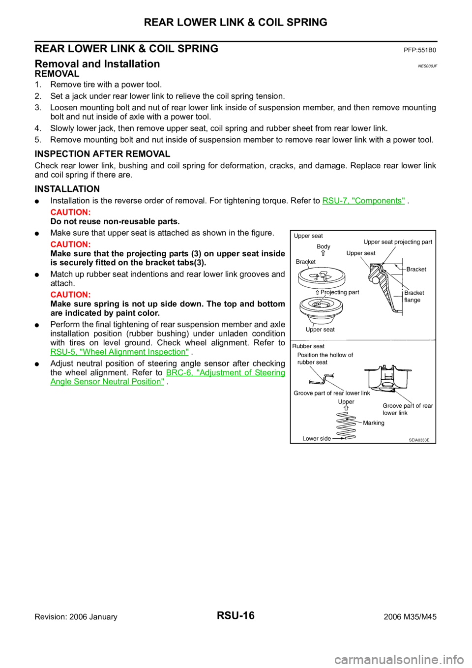
Make sure that upper seat is attached as shown in the figure.
CAUTION:
Make sure that the projecting parts (3) on upper seat inside
is securely fitted on the bracket tabs(3).
Match up rubber seat indentions and rear lower link grooves and
attach.
CAUTION:
Make sure spring is not up side down. The top and bottom
are indicated by paint color.
Perform the final tightening of rear suspension member and axle
installation position (rubber bushing) under unladen condition
with tires on level ground. Check wheel alignment. Refer to
RSU-5, "
Wheel Alignment Inspection" .
Adjust neutral position of steering angle sensor after checking
the wheel alignment. Refer to BRC-6, "
Adjustment of Steering
Angle Sensor Neutral Position" .
SEIA0333E
Page 5444 of 5621
![INFINITI M35 2006 Factory Service Manual TROUBLE DIAGNOSIS
STC-29
[RAS]
C
D
E
F
H
I
J
K
L
MA
B
STC
Revision: 2006 January2006 M35/M45
How to Erase Self-Diagnostic Results
1. Perform applicable inspection of malfunctioning item and then repai INFINITI M35 2006 Factory Service Manual TROUBLE DIAGNOSIS
STC-29
[RAS]
C
D
E
F
H
I
J
K
L
MA
B
STC
Revision: 2006 January2006 M35/M45
How to Erase Self-Diagnostic Results
1. Perform applicable inspection of malfunctioning item and then repai](/img/42/57023/w960_57023-5443.png)
TROUBLE DIAGNOSIS
STC-29
[RAS]
C
D
E
F
H
I
J
K
L
MA
B
STC
Revision: 2006 January2006 M35/M45
How to Erase Self-Diagnostic Results
1. Perform applicable inspection of malfunctioning item and then repair or replace.
2. Start engine, and touch “START (NISSAN BASED VHCL)” “RAS/HICAS” “SELF-DIAG RESULTS” and
“ERASE” in this order to erase the diagnostic memory.
CAUTION:
If memory cannot be erased, repeat step 1, 2.
3. Perform self-diagnosis again, and make sure that DTC memory is erased.
C1912 MOTOR_VOLTAGE [BAD_OBSTRCT] (ꞏ b)The motor power supply voltage is
inputting for some time with motor
power supply OFF by RAS control
unit.STC-35
C1913 MOTOR_OUTPUT [ABNORMAL_SIG] (ꞏ a)When the motor current value is
10A or more, actual output is
excessively low and the condition
continues for some time.STC-37
C1902 MOTOR_OUTPUT [REV_CURRENT] (ꞏ c)The current flows in the opposite
direction when the motor current is
output. STC-37
C1903 MOTOR_OUTPUT [NO_CURRENT] (ꞏ d)The current flows when the motor
current is not output. STC-37
C1904 MOTOR_OUTPUT [OVERCURRENT] (ꞏ e)The excessive high current flows
when the motor current is output.STC-37
C1910 MOTOR_OUTPUT [MOTOR_LOCK] (ꞏ b)When 17 A or more current flows to
the motor, the rear wheel steering
angle sensor signal does not
change for some time.STC-37
C1919 VEHICLE_SPEED_SEN [NO_SIGNAL]No vehicle speed signal is input for
some time.STC-38
C1900
CONTROL_UNIT [ABNORMAL1 - 9] Control unit malfunctionSTC-35
C1901
C1905
C1906
C1907
C1908
C1909
C1922
C1928
C1920 STEERING_ANGLE_SEN [NO_SIGNAL]No steering angle signal is input for
some time.STC-38
C1926 STEERING_ANGLE_SEN
An unexpected signal is input.
Steering angle sensor outputs the
malfunction signal.STC-38
C1929 VDCABS actuator and electric unit (con-
trol unit) outputs the malfunction
signal.STC-42
U1000 CAN COMM CIRCUITWhen a control unit (except for
RAS) is not transmitting or receiving
CAN communication signal 2 sec-
onds or less.STC-43
U1010 CONTROL_UNIT [CAN]When detected error during the ini-
tial diagnosis of CAN controller of
each control unit.STC-43
DTC code Diagnostic item Diagnostic item is detected when... Check items
Page 5466 of 5621

TF-1
TRANSFER
D DRIVELINE/AXLE
CONTENTS
C
E
F
G
H
I
J
K
L
M
SECTION TF
A
B
TF
Revision: 2006 January2006 M35/M45
TRANSFER
PRECAUTIONS .......................................................... 3
Precautions for Supplemental Restraint System
(SRS) “AIR BAG” and “SEAT BELT PRE-TEN-
SIONER” .................................................................. 3
Precautions .............................................................. 3
Service Notice or Precautions .................................. 4
PREPARATION ........................................................... 5
Special Service Tools ............................................... 5
Commercial Service Tools ........................................ 7
NOISE, VIBRATION AND HARSHNESS (NVH)
TROUBLESHOOTING ................................................ 8
NVH Troubleshooting Chart ..................................... 8
TRANSFER FLUID ..................................................... 9
Replacement ............................................................ 9
DRAINING ............................................................. 9
FILLING ................................................................. 9
Inspection ................................................................. 9
FLUID LEAKAGE AND FLUID LEVEL .................. 9
AWD SYSTEM .......................................................... 10
Power Transfer Diagram ........................................ 10
System Description ................................................ 10
DESCRIPTION .................................................... 10
ELECTRIC CONTROLLED COUPLING .............. 11
AWD CONTROL UNIT ......................................... 11
AWD WARNING LAMP ....................................... 12
System Diagram ..................................................... 12
COMPONENTS FUNCTION DESCRIPTION ..... 13
CAN Communication .............................................. 13
SYSTEM DESCRIPTION .................................... 13
TROUBLE DIAGNOSIS ............................................ 14
Fail-Safe Function .................................................. 14
How to Perform Trouble Diagnosis ........................ 14
BASIC CONCEPT ............................................... 14
Location of Electrical Parts ..................................... 15
Circuit Diagram ...................................................... 16
Wiring Diagram — AWD — .................................... 17
Trouble Diagnosis Chart for Symptoms ................. 20
AWD Control Unit Input/Output Signal Reference
Values .................................................................... 20AWD CONTROL UNIT INSPECTION TABLE ..... 20
CONSULT-II Function (ALL MODE AWD/4WD) ..... 21
FUNCTION .......................................................
... 21
CONSULT-II SETTING PROCEDURE ................ 22
SELF-DIAG RESULT MODE ............................... 22
DATA MONITOR MODE ...................................... 24
ACTIVE TEST MODE ......................................... 25
AWD CONTROL UNIT PART NUMBER ............. 25
TROUBLE DIAGNOSIS FOR SYSTEM .................... 26
Power Supply Circuit for AWD Control Unit ............ 26
CONSULT-II REFERENCE VALUE IN DATA
MONITOR MODE ................................................ 26
DIAGNOSTIC PROCEDURE .............................. 26
AWD Control Unit ................................................... 27
DIAGNOSTIC PROCEDURE .............................. 27
ABS System ........................................................... 27
DIAGNOSTIC PROCEDURE .............................. 27
AWD Solenoid ........................................................ 28
CONSULT-II REFERENCE VALUE IN DATA
MONITOR MODE ................................................ 28
DIAGNOSTIC PROCEDURE .............................. 28
COMPONENT INSPECTION .............................. 30
AWD Actuator Relay ............................................... 31
CONSULT-II REFERENCE VALUE IN DATA
MONITOR MODE ................................................ 31
DIAGNOSTIC PROCEDURE .............................. 31
Engine Control Signal ............................................. 32
DIAGNOSTIC PROCEDURE .............................. 32
CAN Communication Line ...................................... 32
DIAGNOSTIC PROCEDURE .............................. 32
TROUBLE DIAGNOSIS FOR SYMPTOMS .............. 33
AWD Warning Lamp Does Not Turn ON When The
Ignition Switch Is Turned to ON .............................. 33
DIAGNOSTIC PROCEDURE .............................. 33
AWD Warning Lamp Does Not Turn OFF Several
Seconds after Engine Started ................................. 33
DIAGNOSTIC PROCEDURE .............................. 33
Heavy Tight-Corner Braking Symptom Occurs
When The Vehicle Is Driven and The Steering Wheel
Is Turned Fully to Either Side after The Engine Is
Page 5478 of 5621

AWD SYSTEM
TF-13
C
E
F
G
H
I
J
K
L
MA
B
TF
Revision: 2006 January2006 M35/M45
COMPONENTS FUNCTION DESCRIPTION
CAN CommunicationNDS000DE
SYSTEM DESCRIPTION
CAN (Controller Area Network) is a serial communication line for real time application. It is an on-vehicle mul-
tiplex communication line with high data communication speed and excellent error detection ability. Many elec-
tronic control units are equipped onto a vehicle, and each control unit shares information and links with other
control units during operation (not independent). In CAN communication, control units are connected with 2
communication lines (CAN H line, CAN L line) allowing a high rate of information transmission with less wiring.
Each control unit transmits/receives data but selectively reads required data only.
For details, refer to LAN-34, "
CAN Communication Unit" .
Component parts Function
AWD control unit
Controls driving force distribution by signals from each sensor and switch from rear wheel driving
mode (0:100) to AWD mode (50:50).
2WD mode is available by fail-safe function if malfunction is detected in AWD system.
Wheel sensors Detects wheel speed.
AWD solenoid Controls electric controlled coupling by command current from AWD control unit.
Electric controlled coupling Transmits driving force to front final drive.
AWD warning lamp
Illuminates if malfunction is detected in electrical system of AWD system.
There is 1 blink in 2 seconds if rotation difference of front wheels and rear wheels is large.
There are 2 blinks in 1 second if load is still applied to driving parts.
ABS actuator and electric unit
(control unit)Transmits the following signals via CAN communication to AWD control unit.
Vehicle speed signal
Stop lamp switch signal (brake signal)
ECMTransmits the following signals via CAN communication to AWD control unit.
Accelerator pedal position signal
Engine speed signal
Unified meter and A/C amp. Transmits conditions of parking brake switch via CAN communication to AWD control unit.
Page 5487 of 5621

TF-22
TROUBLE DIAGNOSIS
Revision: 2006 January2006 M35/M45
CONSULT-II SETTING PROCEDURE
Refer to GI-39, "CONSULT-II Start Procedure" .
SELF-DIAG RESULT MODE
Operation Procedure
1. Perform “CONSULT-II Start Procedure”. Refer to GI-39, "CONSULT-II Start Procedure" .
2. Start engine and drive at 30 km/h (19 MPH) or more for approx. 1 minute.
3. Stop vehicle. With engine at idle, touch “SELF-DIAG RESULTS”.
Display shows malfunction experienced since the last erasing
operation.
NOTE:
The details for “TIME” are as follow:
–“0”: Error currently detected with AWD control unit.
–Except for “0”: Error detected in the past and memorized
with AWD control unit.
Detects frequency of driving after DTC occurs (frequency
of turning ignition switch “ON/OFF”).
Display Item List
CAUTION:
If “CAN COMM CIRCUIT [U1000]” is displayed with other DTCs, first perform the trouble diagnosis for CAN communica-
tion line.
Make sure that ABS warning lamp turns OFF by driving for a minute at vehicle speed of 30 km/h (19 MPH) or more after
turning ignition switch “OFF” if AWD warning lamp turns ON with system malfunction of “ABS SYSTEM [C1203]”. AWD
warning lamp may not turn OFF if it is normal unless ignition switch turns OFF at once and engine restarts after that.
How to Erase Self-Diagnostic Results
1. Perform applicably inspection of malfunctioning item and then repair or replace.
2. Start engine and drive at 30 km/h (19 MPH) or more for approx. 1 minute.
3. Make sure that ABS warning lamp turns OFF.
CAN diagnostic support monitorThe results of transmit/receive diagnosis of CAN communication can be read.LAN-20
Active testDiagnostic Test Mode in which CONSULT-II drives some actuators apart from
the AWD control unit and also shifts some parameters in a specified range.TF-25
ECU part numberAWD control unit part number can be read.TF-25
Diagnostic test mode FunctionReference
page
SDIA2217E
Items (CONSULT-II screen
terms)Diagnostic item is detected when... Check item
CONTROLLER FAILURE
[C1201]Malfunction has occurred inside AWD control unit.TF-27, "
AWD Control Unit"
ABS SYSTEM
[C1203]Malfunction related to wheel sensor has been detected by ABS actu-
ator and electric unit (control unit).TF-27, "ABS System"
4WD SOLENOID
[C1204]Malfunction related to AWD solenoid has been detected.TF-28, "AWD Solenoid"
4WD ACTUATOR RLY
[C1205]Malfunction has been detected from AWD actuator relay integrated
with AWD control unit, or malfunction related to AWD solenoid has
been detected.TF-31, "AWD Actuator
Relay" or TF-28, "AWD
Solenoid"
ENGINE SIGNAL 1
[C1210]Malfunction has been detected from ECM.TF-32, "Engine Control Sig-
nal"
CAN COMM CIRCUIT
[U1000]Malfunction has been detected from CAN communication line.TF-32, "CAN Communica-
tion Line"
NO DTC IS DETECTED.
FURTHER TESTING MAY BE
REQUIRED.No NG item has been detected. —
Page 5488 of 5621

TROUBLE DIAGNOSIS
TF-23
C
E
F
G
H
I
J
K
L
MA
B
TF
Revision: 2006 January2006 M35/M45
NOTE:
Make sure that ABS warning lamp turns OFF by driving for a minute at vehicle speed of 30 km/h
(19 MPH) or more after turning ignition switch “OFF” if AWD warning lamp turns ON with system
malfunction of “ABS SYSTEM [C1203]”. AWD warning lamp may not turn OFF if it is normal unless
ignition switch turns OFF at once and engine restarts after that.
4. Turn ignition switch “OFF” to erase memory.
5. Start engine and select “SELF-DIAG RESULTS” mode for “ALL MODE AWD/4WD” with CONSULT-II.
6. Touch “ERASE” on CONSULT-II screen to erase DTC memory.
CAUTION:
If memory cannot be erased, perform applicably diagnosis.
7. Drive at 30 km/h (19 MPH) or more for approx. 1 minute. Be sure AWD warning lamp is OFF.
Page 5492 of 5621

TROUBLE DIAGNOSIS FOR SYSTEM
TF-27
C
E
F
G
H
I
J
K
L
MA
B
TF
Revision: 2006 January2006 M35/M45
2. CHECK GROUND CIRCUIT
1. Turn ignition switch “OFF”.
2. Disconnect AWD control unit harness connector.
3. Check continuity between AWD control unit harness connector
F109 terminals 10, 11 and ground.
Also check harness for short to ground and short to power.
OK or NG
OK >> GO TO 3.
NG >> Repair open circuit or short to ground or short to power
in harness or connectors.
3. CHECK DTC
Start engine.
Does AWD warning lamp turn OFF?
YES >>INSPECTION END
NO >> Perform the self-diagnosis, repair or replace damaged parts. Refer to TF-22, "
SELF-DIAG
RESULT MODE" .
AWD Control UnitNDS000DO
DIAGNOSTIC PROCEDURE
Check the following if “CONTROLLER FAILURE [C1201]” is displayed in self-diagnosis results of CON-
SULT-II.
1. PERFORM SELF-DIAGNOSIS
With CONSULT-II
1. Turn ignition switch “ON”. (Do not start engine.)
2. Select “SELF-DIAG RESULTS” mode for “ALL MODE AWD/4WD” with CONSULT-II.
3. Touch “ERASE”.
4. Turn ignition switch “OFF” and wait at least 10 seconds.
5. Perform the self-diagnosis again.
Is the
“CONTROLLER FAILURE [C1201]” displayed?
YES >> Replace AWD control unit. Refer to TF-39, "AWD CONTROL UNIT" .
NO >>INSPECTION END
ABS SystemNDS000DP
DIAGNOSTIC PROCEDURE
Check the following if “ABS SYSTEM [C1203]” is displayed in self-diagnosis results of CONSULT-II.
1. CHECK DTC WITH ABS ACTUATOR AND ELECTRIC UNIT (CONTROL UNIT)
Perform self-diagnosis with ABS actuator and electric unit (control unit). Refer to BRC-23, "
Self-Diagnosis" .
Is any malfunction detected by self-diagnosis?
YES >> Check the malfunctioning system.
NO >> GO TO 2.Continuity should exist.
SDIA1883E