horn INFINITI M35 2006 Factory Owner's Guide
[x] Cancel search | Manufacturer: INFINITI, Model Year: 2006, Model line: M35, Model: INFINITI M35 2006Pages: 5621, PDF Size: 65.56 MB
Page 4850 of 5621

IPDM E/R (INTELLIGENT POWER DISTRIBUTION MODULE ENGINE ROOM)
PG-23
C
D
E
F
G
H
I
J
L
MA
B
PG
Revision: 2006 January2006 M35/M45
CAN DIAG SUPPORT MNTR
Refer to LAN-20, "CAN Diagnostic Support Monitor" in LAN section.
ACTIVE TEST
Operation Procedure
1. Touch “ACTIVE TEST” on “SELECT DIAG MODE” screen.
2. Touch item to be tested.
3. Touch “START”, and confirm its operation.
4. Touch “STOP” while testing to stop the operation.
Test item CONSULT-II screen display Description
Tail lamp operation TAIL LAMP With a certain ON-OFF operation, the tail lamp relay can be operated.
Rear window defogger oper-
ationREAR DEFOGGERWith a certain ON-OFF operation, the rear window defogger relay can
be operated.
Front wiper (HI, LO) opera-
tionFRONT WIPERWith a certain operation (OFF, HI ON, LO ON), the front wiper relay
(Lo, Hi) can be operated.
Cooling fan operation MOTOR FAN With a certain operation (1, 2, 3, 4), the cooling fan can be operated.
Lamp (HI, LO, FOG) opera-
tionLAMPSWith a certain operation (OFF, HI ON, LO ON, FOG ON), the lamp
relay (Lo, Hi, Fog) can be operated.
Horn operation HORN Push “ON” button, horn relay operates 20ms.
Page 4851 of 5621

PG-24
IPDM E/R (INTELLIGENT POWER DISTRIBUTION MODULE ENGINE ROOM)
Revision: 2006 January2006 M35/M45
Auto Active TestNKS004E7
DESCRIPTION
In auto active test mode, operation inspection can be performed when IPDM E/R sends a drive signal to the
following systems:
Rear window defogger
Front wiper (LO, HI)
Tail lamps, parking lamps and license plate lamps
Front fog lamps
Headlamps (LO, HI)
A/C compressor (magnetic clutch)
Cooling fan
Oil pressure warning lamp
OPERATION PROCEDURE
1. Close hood and front door (passenger side), and then lift wiper arms away from windshield (to prevent
glass damage by wiper operation).
NOTE:
When auto active test is performed with hood opened, sprinkle water on windshield beforehand.
2. Turn ignition switch OFF.
3. Turn ignition switch ON, and within 20 seconds, press driver's door switch 10 times (close other doors).
Then turn ignition switch OFF.
4. Turn ignition switch ON within 10 seconds after ignition switch OFF.
5. When auto active test mode is actuated, horn chirps once. Oil pressure warning lamp starts blinking.
6. After a series of operations is repeated three times, auto active test is completed.
NOTE:
When auto active test mode has to be cancelled halfway, turn ignition switch OFF.
CAUTION:
Never start the engine.
If the engine starting operation is made, delete DTC on the self-diag results of CONSULT-II.
Refer to BL-81, "
CONSULT-II Application Items" .
Be sure to inspect GW-52, "Door Switch Check" when the auto active test cannot be performed.
Page 4921 of 5621

PG-94
HARNESS
Revision: 2006 January2006 M35/M45
ETC3 EC Electric Throttle Control Motor
F/FOG LT Front Fog Lamp
F/PUMP EC Fuel Pump
FPCM EC Fuel Pump Control Module
FTS AT A/T Fluid Temperature Sensor Circuit
FTTS EC Fuel Tank Temperature Sensor
FUELB1 EC Fuel Injection System Function (Bank 1)
FUELB2 EC Fuel Injection System Function (Bank 2)
H/LAMP LT Headlamp
HORN WW Horn
HSEAT SE Heated Seat
I/KEY BL Intelligent Key System
I/MIRR GW Inside Mirror (Auto Anti-Dazzling Mirror)
IATS EC Intake Air Temperature Sensor
ICC ACS Intelligent Cruise Control System
ICC/BS EC ICC Brake Switch
ICC/SW EC ICC Steering Switch
ICCBOF EC ICC Brake Switch
IGNSYS EC Ignition System
ILL LT Illumination
INJECT EC Injector
IVCB1 EC Intake Valve Timing Control Solenoid Valve Bank 1
IVCB2 EC Intake Valve Timing Control Solenoid Valve Bank 2
IVCSB1 EC Intake Valve Timing Control Position Sensor Bank 1
IVCSB2 EC Intake Valve Timing Control Position Sensor Bank 2
IVTB1 EC Intake Valve Timing Control System (Bank 1)
IVTB2 EC Intake Valve Timing Control System (Bank 2)
KS EC Knock Sensor
LDW DI Lane Departure Warning System
MAFS EC Mass Air Flow Sensor
MAIN AT Main Power Supply and Ground Circuit
MAIN EC Main Power Supply and Ground Circuit
METER DI Speedometer, Tachometer, Temp., Oil and Fuel Gauges
MIL/DL EC MIL & Data Link Connector
MIRROR GW Door Mirror
MMSW AT Manual Mode Switch
NATS BL Nissan Anti-Theft System
NONDTC AT Non-Detective Items
O2H2B1 EC Heated Oxygen Sensor 2 Heater Bank 1
O2H2B2 EC Heated Oxygen Sensor 2 Heater Bank 2
O2S2B1 EC Heated Oxygen Sensor 2 Bank 1
O2S2B2 EC Heated Oxygen Sensor 2 Bank 2
P/SCKT WW Power Socket
PDU PG Power Distribution Unit Code Section Wiring Diagram Name
Page 5401 of 5621

SRS-40
SPIRAL CABLE
Revision: 2006 January2006 M35/M45
SPIRAL CABLEPFP:25554
Removal and InstallationNHS0009D
REMOVAL
CAUTION:
Before servicing, turn ignition switch OFF, disconnect both battery terminal and wait at least 3
minutes.
Do not use air tools or electric tools for servicing.
Do not disassemble the spiral cable.
Do not arrow oil, grease, detergent or water to come in contact with the spiral cable.
Do not make an impact to the spiral cable by dropping etc. Replace the spiral cable if it has been
dropped or sustained an impact.
1. Remove the air bag module. Refer to SRS-38, "
Removal and Installation" .
2. Remove the steering wheel. Refer to PS-12, "
Removal and Installation" .
3. Remove the column cover.
4. Remove the wiper washer switch, then remove light and turn signal switch from the spiral cable.
5. Remove the spiral cable.
Disconnect the horn switch connector (shown as A in the fig-
ure).
Disconnect the spiral cable connector (shown as B in the fig-
ure).
Loosen the spiral cable fixing screws.
Shift the spiral cable forward a bit while pushing the pawl
located above the spiral cable.
Disconnect the steering wheel switch connector (shown as C
in the figure).
NOTE:
Disconnect the spiral cable connector after disconnecting the
horn switch connector.
INSTALLATION
Install in the reverse order of removal.
PHIA1112E
1. Steering wheel 2. Steering column cover (lower) 3. Light and turn signalswitchs
4. Wiper washer switch 5. Spiral cable 6. Steering column cover (upper)
7. Steering column assembly 8. Driver air bag module connector
PHIA0886J
Page 5568 of 5621

WW-1
WIPER, WASHER & HORN
K ELECTRICAL
CONTENTS
C
D
E
F
G
H
I
J
L
M
SECTION WW
A
B
WW
Revision: 2006 January2006 M35/M45
WIPER, WASHER & HORN
PRECAUTION ............................................................ 3
Precautions for Supplemental Restraint System
(SRS) “AIR BAG” and “SEAT BELT PRE-TEN-
SIONER” .................................................................. 3
FRONT WIPER AND WASHER SYSTEM .................. 4
Components Parts and Harness Connector Loca-
tion ........................................................................... 4
System Description .................................................. 4
OUTLINE ............................................................... 5
LOW SPEED WIPER OPERATION ...................... 5
HIGH SPEED WIPER OPERATION ..................... 6
INTERMITTENT OPERATION .............................. 6
AUTO STOP OPERATION .................................... 7
WASHER OPERATION ......................................... 7
MIST OPERATION ................................................ 7
FAIL-SAFE FUNCTION ......................................... 7
COMBINATION SWITCH READING FUNCTION ..... 8
CAN Communication System Description ............... 11
CAN Communication Unit ....................................... 11
Schematic .............................................................. 12
Wiring Diagram — WIPER — ................................ 13
Terminals and Reference Values for BCM ............. 17
Terminals and Reference Values for IPDM E/R ..... 21
How to Perform Trouble Diagnoses ....................... 21
Preliminary Check .................................................. 22
CHECK POWER SUPPLY AND GROUND CIR-
CUIT .................................................................... 22
CONSULT-II Functions (BCM) ............................... 23
CONSULT-II BASIC OPERATION ....................... 23
WORK SUPPORT ............................................... 24
DATA MONITOR ................................................. 24
ACTIVE TEST ..................................................... 25
CONSULT-II Functions (IPDM E/R) ....................... 26
CONSULT-II BASIC OPERATION ....................... 26
DATA MONITOR ................................................. 27
ACTIVE TEST ..................................................... 27
Front Wiper Does Not Operate .............................. 28
Front Wiper Does Not Return to Stop Position (After
Front Wiper Operate for 10 Seconds, They Stop for
20 Seconds, and After Repeating the Operations Five Times, They Become Inoperative) .................. 31
Front Wiper Does Not Return to Stop Position When
Front Wiper Motor Operates at Low Speed (After
Front Wiper Operate for 10 Seconds, They Stop for
20 Seconds, and After Repeating the Operations
Five Times, They Become Inoperative) .................. 33
Front Wiper Does Not Return to Stop Position When
Front Wiper Motor Operates at HIGH Speed (After
Front Wiper Operate for 10 Seconds, They Stop for
20 Seconds, and After Repeating the Operations
Five Times, They Become Inoperative) .................. 34
Only Front Wiper LO Does Not Operate ................. 36
Only Front Wiper HI Does Not Operate .................. 37
Only Front Wiper Intermittent Does Not Operate ... 39
Front Wiper Interval Time Is Not Controlled by Vehi-
cle Speed ................................................................ 39
Front Wiper Intermittent Operation Switch Position
Cannot Be Adjusted .............................................
... 40
Wiper Does Not Wipe When Front Washer Operates
... 40
Front Wiper Does Not Stop ..................................... 41
Removal and Installation of Front Wiper Arms,
Adjustment of Wiper Arms Stop Location ............... 42
REMOVAL ........................................................
... 42
INSTALLATION ................................................... 42
ADJUSTMENT .................................................... 42
Removal and Installation of Front Wiper Drive
Assembly ................................................................ 43
REMOVAL ........................................................
... 43
INSTALLATION ................................................... 43
Disassembly and Assembly of Front Wiper Drive
Assembly ................................................................ 43
DISASSEMBLY ................................................... 44
ASSEMBLY ......................................................... 44
Washer Nozzle Adjustment .................................... 44
Washer Tube Layout .............................................. 45
Removal and Installation of Front Washer Nozzle ... 45
REMOVAL ........................................................
... 45
INSTALLATION ................................................... 45
Inspection for Washer Nozzle ................................. 46
Page 5569 of 5621

WW-2Revision: 2006 January2006 M35/M45 CHECK VALVE INSPECTION ............................. 46
Inspection of Front Wiper and Washer Switch Circuit ... 46
Removal and Installation of Front Wiper and Washer
Switch ..................................................................... 46
REMOVAL ........................................................
... 46
INSTALLATION .................................................... 46
Removal and Installation of Washer Tank .............. 47
REMOVAL ........................................................
... 47
INSTALLATION .................................................... 47
Removal and Installation of Washer Pump ............. 48
REMOVAL ........................................................
... 48
INSTALLATION .................................................... 48
CIGARETTE LIGHTER ............................................. 49
Wiring Diagram — CIGAR — ................................. 49
Removal and Installation ........................................ 50
REMOVAL ........................................................
... 50
INSTALLATION .................................................... 50POWER SOCKET ..................................................... 51
Wiring Diagram — P/SCKT — ................................ 51
Removal and Installation of Center Console Box
Power Socket .......................................................... 52
REMOVAL ............................................................ 52
INSTALLATION .................................................... 52
Removal and Installation of Center Console Box
Rear Side Power Socket ......................................... 52
REMOVAL ............................................................ 52
INSTALLATION .................................................... 52
HORN ........................................................................ 53
Wiring Diagram — HORN — .................................. 53
Removal and Installation ......................................... 54
REMOVAL ............................................................ 54
INSTALLATION .................................................... 54
Page 5620 of 5621

HORN
WW-53
C
D
E
F
G
H
I
J
L
MA
B
WW
Revision: 2006 January2006 M35/M45
HORNPFP:25610
Wiring Diagram — HORN —NKS003XE
TKWT3221E
Page 5621 of 5621

WW-54
HORN
Revision: 2006 January2006 M35/M45
Removal and InstallationNKS003XF
REMOVAL
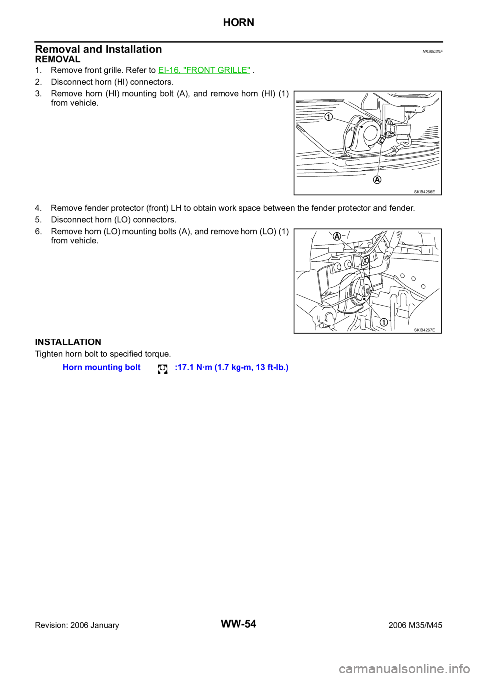
1. Remove front grille. Refer to EI-16, "FRONT GRILLE" .
2. Disconnect horn (HI) connectors.
3. Remove horn (HI) mounting bolt (A), and remove horn (HI) (1)
from vehicle.
4. Remove fender protector (front) LH to obtain work space between the fender protector and fender.
5. Disconnect horn (LO) connectors.
6. Remove horn (LO) mounting bolts (A), and remove horn (LO) (1)
from vehicle.
INSTALLATION
Tighten horn bolt to specified torque.
SKIB4266E
SKIB4267E
Horn mounting bolt :17.1 Nꞏm (1.7 kg-m, 13 ft-lb.)