air condition INFINITI M35 2006 Factory Service Manual
[x] Cancel search | Manufacturer: INFINITI, Model Year: 2006, Model line: M35, Model: INFINITI M35 2006Pages: 5621, PDF Size: 65.56 MB
Page 3609 of 5621

GW-90
REAR WINDOW DEFOGGER
Revision: 2006 January2006 M35/M45
2. CHECK POWER SUPPLY CIRCUIT 1
1. Turn ignition switch ON.
2. Check voltage between fuse block (J/B) connector and ground.
OK or NG
OK >> GO TO 3.
NG >> Repair or replace harness.
3. CHECK POWER SUPPLY CIRCUIT 2
Check voltage between fuse block (J/B) connector and ground.
OK or NG
OK >> GO TO 4.
NG >> Replace fuse block (J/B).
4. CHECK DOOR MIRROR CIRCUIT
1. Turn ignition switch OFF.
2. Disconnect fuse block (J/B) and door mirror connector.
3. Check continuity between fuse block (J/B) connector and door mirror connector.
4. Check continuity between fuse block (J/B) connector and
ground.
OK or NG
OK >> GO TO 5.
NG >> Repair or replace harness between fuse block (J/B) and malfunctioning door mirror connector.
Terminals
Condition of rear
window defogger
switchVoltage (V)
(Approx.) (+)
(–)
Fuse block
connectorTerminal
E101 2C GroundON Battery voltage
OFF 0
PIIB5993E
Terminals
Condition of rear
window defogger
switchVoltage (V)
(Approx.) (+)
(–)
Fuse block
connectorTerminal
M5 5B GroundON Battery voltage
OFF 0
PIIB5992E
AB
Continuity
Fuse block
connectorTe r m i n a lDoor mirror
connectorTerminal
M5 5BD2 (LH)
D39 (RH)4Yes
A
GroundContinuity
Fuse block connector Terminal
M5 5B No
PIIB5988E
Page 3610 of 5621

REAR WINDOW DEFOGGER
GW-91
C
D
E
F
G
H
J
K
L
MA
B
GW
Revision: 2006 January2006 M35/M45
5. CHECK GROUND CIRCUIT
Check continuity between door mirror connector and ground.
OK or NG
OK >> GO TO 6.
NG >> Repair or replace harness.
6. CHECK DOOR MIRROR DEFOGGER
1. Connect door mirror connector.
2. Check door mirror.
OK or NG
OK >> Check condition of harness and connector.
NG >> Replace malfunctioning door mirror.
Driver Side Door Mirror Defogger Circuit CheckNIS0022W
1. CHECK POWER SUPPLY CIRCUIT
1. Turn ignition switch OFF.
2. Disconnect door mirror LH connector.
3. Turn ignition switch ON.
4. Check voltage between door mirror LH connector and ground.
OK or NG
OK >> GO TO 2.
NG >> Repair or replace harness between fuse block (J/B) and
door mirror LH.
Door mirror connector Terminal
GroundContinuity
D2 (LH)
D39 (RH)8Yes
PIIB5989E
Door mirror connector Terminal Continuity
D2 (LH)
D39 (RH)48 Yes
PIIB5990E
Te r m i n a l s
Condition of rear
window defogger
switchVoltage (V)
(Approx.) (+)
(–)
Door mirror LH
connectorTe r m i n a l
D2 4 GroundON Battery voltage
OFF 0
PIIB5991E
Page 3611 of 5621

GW-92
REAR WINDOW DEFOGGER
Revision: 2006 January2006 M35/M45
2. CHECK GROUND CIRCUIT
1. Turn ignition switch OFF.
2. Check continuity between door mirror LH connector and ground.
OK or NG
OK >> GO TO 3.
NG >> Repair or replace harness between door mirror LH and
ground.
3. CHECK DOOR MIRROR DEFOGGER
1. Connector door mirror LH connector.
2. Check door mirror LH.
OK or NG
OK >> Check condition of harness and connector.
NG >> Replace door mirror LH.
Passenger Side Door Mirror Defogger Circuit Check NIS0022X
1. CHECK POWER SUPPLY CIRCUIT
1. Turn ignition switch OFF.
2. Disconnect door mirror RH connector.
3. Turn ignition switch ON.
4. Check voltage between door mirror RH connector and ground.
OK or NG
OK >> GO TO 2.
NG >> Repair or replace harness between fuse block (J/B) and
door mirror RH.
Door mirror LH
connectorTerminal
GroundContinuity
D2 8 Yes
PIIB5989E
Door mirror LH
connectorTerminal Continuity
D2 4 8 Yes
PIIB5990E
Terminals
Condition of rear
window defogger
switchVoltage (V)
(Approx.) (+)
(–)
Door mirror RH
connectorTerminal
D39 4 GroundON Battery voltage
OFF 0
PIIB5991E
Page 3612 of 5621

REAR WINDOW DEFOGGER
GW-93
C
D
E
F
G
H
J
K
L
MA
B
GW
Revision: 2006 January2006 M35/M45
2. CHECK GROUND CIRCUIT
1. Turn ignition switch OFF.
2. Check continuity between door mirror RH connector and ground.
OK or NG
OK >> GO TO 3.
NG >> Repair or replace harness between door mirror RH and
ground.
3. CHECK DOOR MIRROR DEFOGGER
1. Connector RH door mirror connector.
2. Check door mirror RH.
OK or NG
OK >> Check condition of harness and connector.
NG >> Replace door mirror.
Door mirror RH
connectorTerminal
GroundContinuity
D39 8 Yes
PIIB5989E
Door mirror RH
connectorTerminal Continuity
D39 4 8 Yes
PIIB5990E
Page 3629 of 5621

GW-110
REVERSE INTERLOCK DOOR MIRROR SYSTEM
Revision: 2006 January2006 M35/M45
2. CHECK HARNESS CONTINUITY
1. Turn ignition switch OFF.
2. Disconnect automatic drive positioner control unit and door mirror remote control switch connector.
3. Check continuity between automatic drive positioner control unit connector and door mirror remote control
switch connector.
4. Check continuity between automatic drive positioner control unit
connector and ground.
OK or NG
OK >> GO TO 3.
NG >> Repair or replace harness.
3. CHECK CANGEOVER SWITCH
Check door mirror remote control switch.
OK or NG
OK >> GO TO 4.
NG >> Replace door mirror remote control switch.
4. CHECK DOOR MIRROR REMOTE CONTROL SWITCH GROUND CIRCUIT
Check continuity between door mirror remote control switch connector and ground.
OK or NG
OK >> GO TO 5.
NG >> Repair or replace harness.
AB
Continuity Automatic
drive posi-
tioner control
unit connectorTerminalDoor mirror
remote control
switch
connectorTerminal
M62
M953
Ye s
18 2
A
GroundContinuity
Automatic drive
positioner control
unit connectorTerminal
No
M62
18
PIIB6016E
Terminal
Change over switch
conditionContinuity
Door mirror remote control switch
2
13LEFT Yes
Other than above No
3RIGHT Yes
Other than above No
PIIB6017E
Door mirror remote
control switch connectorTerminal
GroundContinuity
M95 13 Yes
PIIB6018E
Page 3631 of 5621
GW-112
REVERSE INTERLOCK DOOR MIRROR SYSTEM
Revision: 2006 January2006 M35/M45
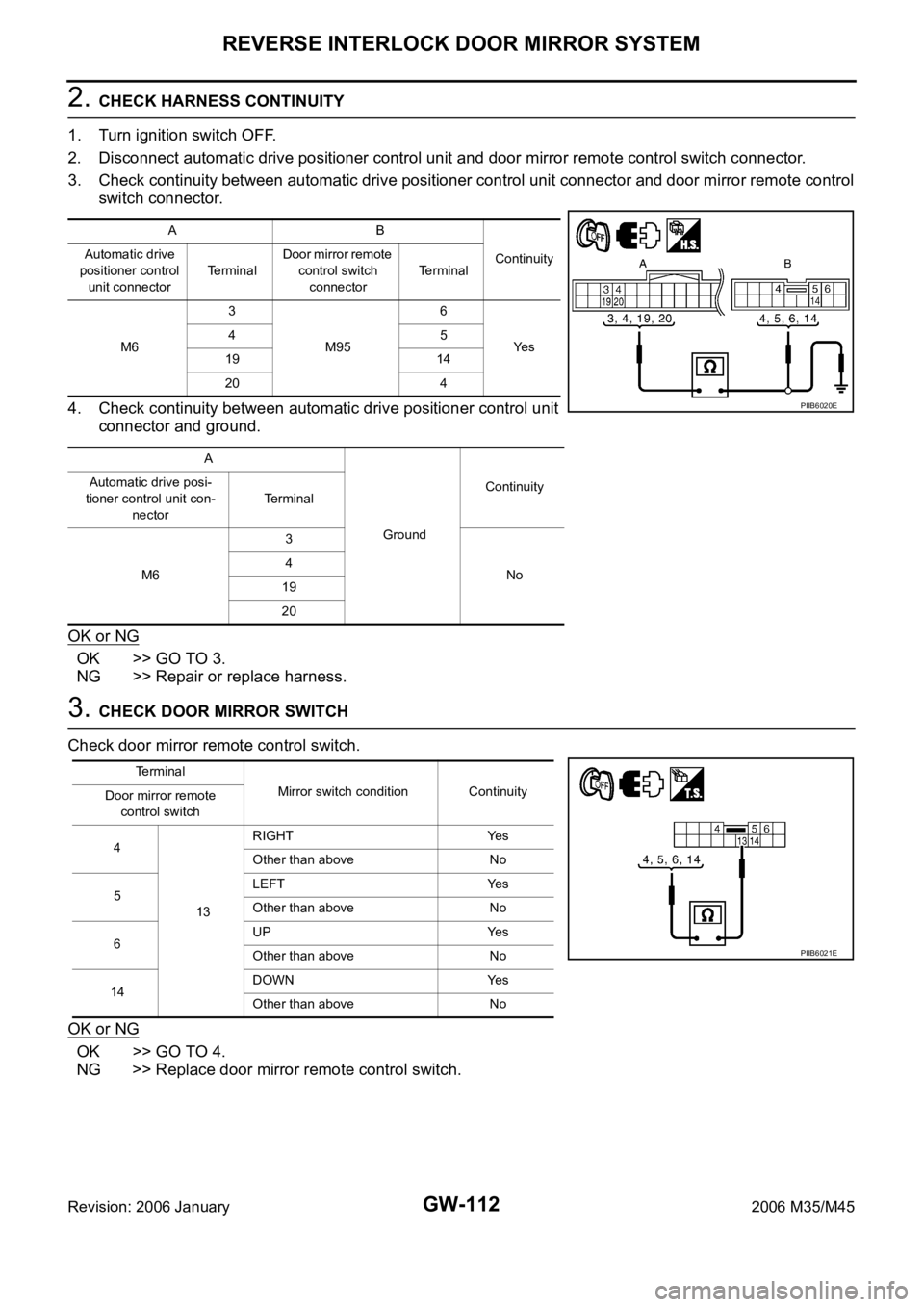
2. CHECK HARNESS CONTINUITY
1. Turn ignition switch OFF.
2. Disconnect automatic drive positioner control unit and door mirror remote control switch connector.
3. Check continuity between automatic drive positioner control unit connector and door mirror remote control
switch connector.
4. Check continuity between automatic drive positioner control unit
connector and ground.
OK or NG
OK >> GO TO 3.
NG >> Repair or replace harness.
3. CHECK DOOR MIRROR SWITCH
Check door mirror remote control switch.
OK or NG
OK >> GO TO 4.
NG >> Replace door mirror remote control switch.
AB
Continuity Automatic drive
positioner control
unit connectorTe r m i n a lDoor mirror remote
control switch
connectorTerminal
M63
M956
Ye s 45
19 14
20 4
A
GroundContinuity Automatic drive posi-
tioner control unit con-
nectorTerminal
M63
No 4
19
20
PIIB6020E
Terminal
Mirror switch condition Continuity
Door mirror remote
control switch
4
13RIGHT Yes
Other than above No
5LEFT Yes
Other than above No
6UP Yes
Other than above No
14DOWN Yes
Other than above No
PIIB6021E
Page 3636 of 5621
REVERSE INTERLOCK DOOR MIRROR SYSTEM
GW-117
C
D
E
F
G
H
J
K
L
MA
B
GW
Revision: 2006 January2006 M35/M45
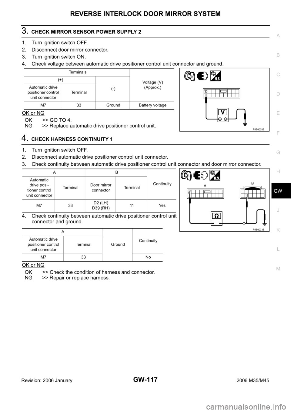
3. CHECK MIRROR SENSOR POWER SUPPLY 2
1. Turn ignition switch OFF.
2. Disconnect door mirror connector.
3. Turn ignition switch ON.
4. Check voltage between automatic drive positioner control unit connector and ground.
OK or NG
OK >> GO TO 4.
NG >> Replace automatic drive positioner control unit.
4. CHECK HARNESS CONTINUITY 1
1. Turn ignition switch OFF.
2. Disconnect automatic drive positioner control unit connector.
3. Check continuity between automatic drive positioner control unit connector and door mirror connector.
4. Check continuity between automatic drive positioner control unit
connector and ground.
OK or NG
OK >> Check the condition of harness and connector.
NG >> Repair or replace harness.
Terminals
Voltage (V)
(Approx.) (+)
(-) Automatic drive
positioner control
unit connectorTerminal
M7 33 Ground Battery voltage
PIIB6028E
AB
Continuity Automatic
drive posi-
tioner control
unit connectorTerminalDoor mirror
connectorTerminal
M7 33D2 (LH)
D39 (RH)11 Ye s
A
GroundContinuity Automatic drive
positioner control
unit connectorTerminal
M7 33 No
PIIB6033E
Page 3637 of 5621
GW-118
REVERSE INTERLOCK DOOR MIRROR SYSTEM
Revision: 2006 January2006 M35/M45
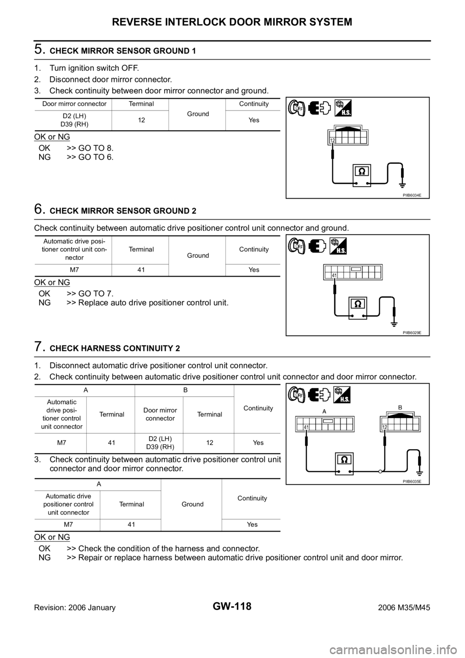
5. CHECK MIRROR SENSOR GROUND 1
1. Turn ignition switch OFF.
2. Disconnect door mirror connector.
3. Check continuity between door mirror connector and ground.
OK or NG
OK >> GO TO 8.
NG >> GO TO 6.
6. CHECK MIRROR SENSOR GROUND 2
Check continuity between automatic drive positioner control unit connector and ground.
OK or NG
OK >> GO TO 7.
NG >> Replace auto drive positioner control unit.
7. CHECK HARNESS CONTINUITY 2
1. Disconnect automatic drive positioner control unit connector.
2. Check continuity between automatic drive positioner control unit connector and door mirror connector.
3. Check continuity between automatic drive positioner control unit
connector and door mirror connector.
OK or NG
OK >> Check the condition of the harness and connector.
NG >> Repair or replace harness between automatic drive positioner control unit and door mirror.
Door mirror connector Terminal
GroundContinuity
D2 (LH)
D39 (RH)12 Yes
PIIB6034E
Automatic drive posi-
tioner control unit con-
nectorTerminal
GroundContinuity
M7 41 Yes
PIIB6029E
AB
Continuity Automatic
drive posi-
tioner control
unit connectorTerminalDoor mirror
connectorTerminal
M7 41D2 (LH)
D39 (RH)12 Yes
A
GroundContinuity Automatic drive
positioner control
unit connectorTerminal
M7 41 Yes
PIIB6035E
Page 3638 of 5621
REVERSE INTERLOCK DOOR MIRROR SYSTEM
GW-119
C
D
E
F
G
H
J
K
L
MA
B
GW
Revision: 2006 January2006 M35/M45
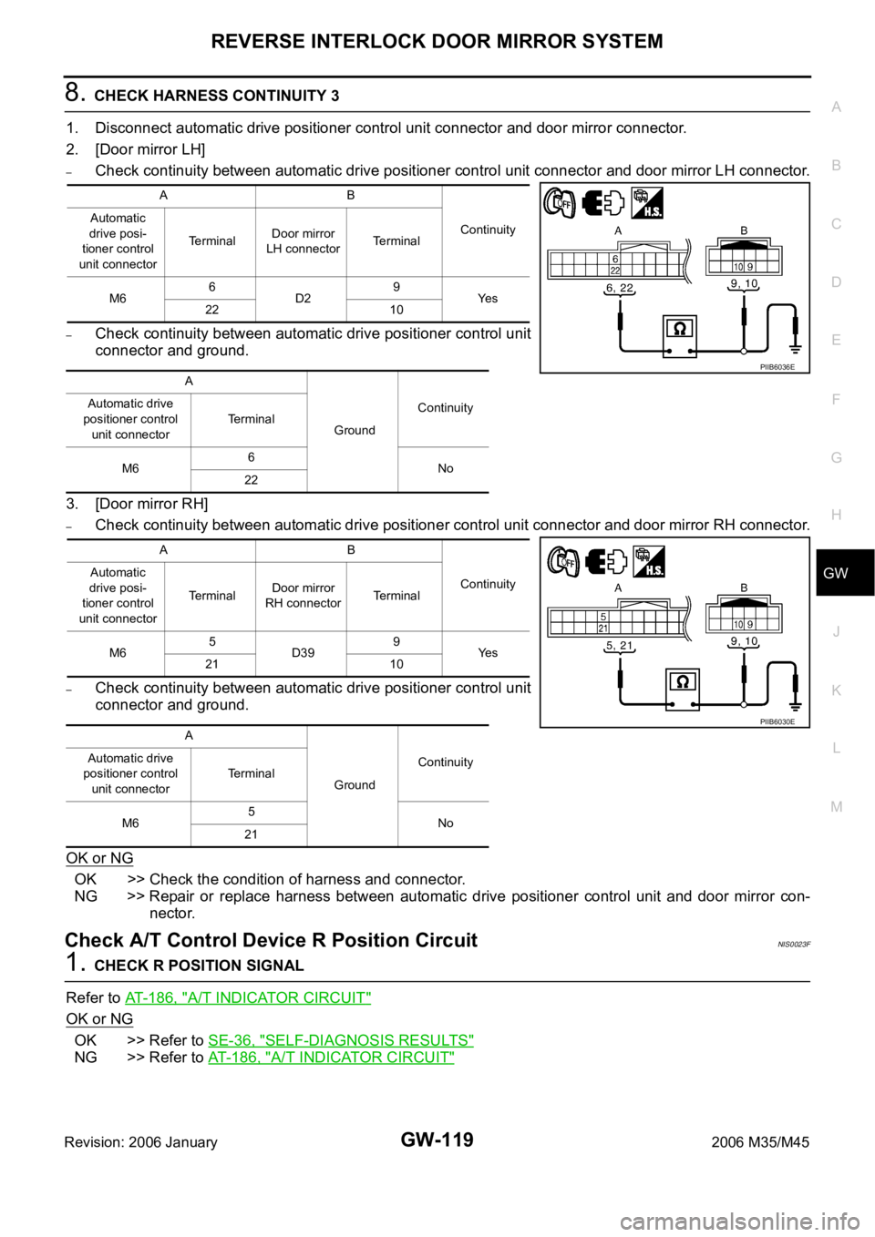
8. CHECK HARNESS CONTINUITY 3
1. Disconnect automatic drive positioner control unit connector and door mirror connector.
2. [Door mirror LH]
–Check continuity between automatic drive positioner control unit connector and door mirror LH connector.
–Check continuity between automatic drive positioner control unit
connector and ground.
3. [Door mirror RH]
–Check continuity between automatic drive positioner control unit connector and door mirror RH connector.
–Check continuity between automatic drive positioner control unit
connector and ground.
OK or NG
OK >> Check the condition of harness and connector.
NG >> Repair or replace harness between automatic drive positioner control unit and door mirror con-
nector.
Check A/T Control Device R Position CircuitNIS0023F
1. CHECK R POSITION SIGNAL
Refer to AT-186, "
A/T INDICATOR CIRCUIT"
OK or NG
OK >> Refer to SE-36, "SELF-DIAGNOSIS RESULTS"
NG >> Refer to AT-186, "A/T INDICATOR CIRCUIT"
AB
Continuity Automatic
drive posi-
tioner control
unit connectorTerminalDoor mirror
LH connectorTerminal
M66
D29
Ye s
22 10
A
GroundContinuity Automatic drive
positioner control
unit connectorTerminal
M66
No
22
AB
Continuity Automatic
drive posi-
tioner control
unit connectorTerminalDoor mirror
RH connectorTerminal
M65
D399
Ye s
21 10
A
GroundContinuity Automatic drive
positioner control
unit connectorTerminal
M65
No
21
PIIB6036E
PIIB6030E
Page 3643 of 5621
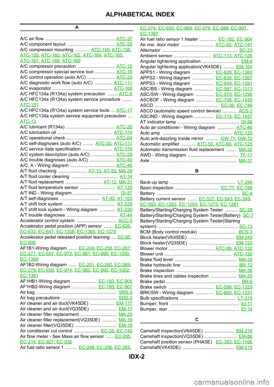
IDX-2
ALPHABETICAL INDEX
A
A/C air flow ...................................................... ATC-37
A/C component layout ..................................... ATC-25
A/C compressor mounting ........... ATC-155, ATC-158,
ATC-159
, ATC-160, ATC-162, ATC-164, ATC-165,
ATC-167
, ATC-168, ATC-169
A/C compressor precaution ............................. ATC-12
A/C compressor special service tool ................ ATC-16
A/C control operation (auto A/C) ...................... ATC-33
A/C diagnostic work flow (auto A/C) .............. ATC-111
A/C evaporator ............................................... ATC-168
A/C HFC134a (R134a) system precaution ........ ATC-6
A/C HFC134a (R134a) system service procedure .......
ATC-151
A/C HFC134a (R134a) system service tools ... ATC-17
A/C HFC134a system service equipment precaution ...
ATC-13
A/C lubricant (R134a) ...................................... ATC-26
A/C lubrication oil ........................................... ATC-174
A/C operational check ...................................... ATC-64
A/C self-diagnoses (auto A/C) ........ ATC-55, ATC-111
A/C service data specification ........................ ATC-174
A/C system description (auto A/C) ................... ATC-29
A/C trouble diagnoses (auto A/C) .................... ATC-40
A/C, A - Wiring diagram ................................... ATC-46
A/T fluid checking ...................... AT-13, AT-53, MA-29
A/T fluid cooler cleaning .................................... AT-14
A/T fluid replacement ............................. AT-12, MA-31
A/T fluid temperature sensor ........................... AT-135
A/T IND - Wiring diagram .................................... DI-57
A/T self-diagnoses ............................... AT-92, AT-103
A/T shift lock system ........................................ AT-229
A/T shift lock system - Wiring diagram ............ AT-230
A/T trouble diagnoses ........................................ AT-44
Accelerator control system ............................... ACC-3
Accelerator pedal position (APP) sensor ........ EC-626,
EC-633
, EC-647, EC-1358, EC-1365, EC-1379
Accelerator pedal released position learning .... EC-95,
EC-806
AF1B1-Wiring diagram ...... EC-249, EC-258, EC-267,
EC-277
, EC-657, EC-972, EC-981, EC-990, EC-1000,
EC-1389
AF1B2-Wiring diagram ...... EC-251, EC-260, EC-269,
EC-279
, EC-659, EC-974, EC-983, EC-992, EC-1002,
EC-1391
AF1HB1-Wiring diagram .................... EC-183, EC-905
AF1HB2-Wiring diagram .................... EC-185, EC-907
Air bag .............................................................. SRS-3
Air bag precautions ........................................... SRS-3
Air cleaner and air duct(VK45DE) ................... EM-177
Air cleaner and air duct(VQ35DE) .................... EM-17
Air cleaner filter replacement ............................ MA-25
Air cleaner filter replacement(VQ35DE) ........... MA-18
Air cleaner filter(VQ35DE) ................................ EM-18
Air conditioner cut control .................... EC-35, EC-745
Air flow meter - See Mass air flow sensor ...... EC-205,
EC-214
, EC-927, EC-936
Air fuel ratio sensor 1 ......... EC-246, EC-256, EC-265, EC-274
, EC-655, EC-969, EC-979, EC-988, EC-997,
EC-1387
Air fuel ratio sensor 1 heater ............. EC-182, EC-904
Air mix. door motor ......................... ATC-83, ATC-141
Alternator ........................................................... SC-23
Ambient sensor ............................. ATC-113, ATC-126
Angular tightening application ............................. EM-6
Angular tightening application(VK45DE) ........ EM-164
APPS1 - Wiring diagram ................. EC-628, EC-1360
APPS2 - Wiring diagram ................. EC-635, EC-1367
APPS3 - Wiring diagram ................. EC-649, EC-1381
ASC/BS - Wiring diagram ............... EC-587, EC-1313
ASC/SW - Wiring diagram .............. EC-570, EC-1296
ASCBOF - Wiring diagram .............. EC-708, EC-1450
ASCD .................................................. EC-36, EC-746
ASCD (automatic speed control device) ........... ACS-3
ASCIND - Wiring diagram ............... EC-715, EC-1457
AT indicator lamp ................................................ DI-56
Auto air conditioner - Wiring diagram ............. ATC-46
Auto amp ...................................................... ATC-125
Auto anti-dazzling inside mirror .......... GW-71, GW-72
Automatic amplifier ........... ATC-53, ATC-66, ATC-125
Automatic transmission fluid replacement ........ MA-32
AWD - Wiring diagram ....................................... TF-17
Axle ................................................................... MA-37
B
Back-up lamp ................................................... LT-246
Basic inspection .................................. EC-77, EC-788
Battery ................................................................. SC-4
Battery current sensor ....... EC-537, EC-543, EC-549,
EC-555
, EC-1263, EC-1269, EC-1275, EC-1281
Battery/Starting/Charging System Tester .......... SC-28
Battery/Starting/Charging System Tester(Battery) SC-7
Battery/Starting/Charging System Tester(Starting
system) .............................................................. SC-13
BCM (Body control module) .............................. BCS-3
Block heater(VK45DE) .................................... EM-249
Block heater(VQ35DE) ................................... EM-123
Blower motor ................................... ATC-89, ATC-132
Blower unit .................................................... ATC-130
Brake fluid level ................................................ MA-35
Brake hydraulic line ........................................... BR-12
Brake inspection ............................................... MA-36
Brake lines and cables inspection .................... MA-35
Brake pedal .......................................................... BR-6
Brake switch ................................... EC-598, EC-1329
BRK/SW - Wiring diagram .............. EC-600, EC-1331
Bulb specifications ........................................... LT-315
Bumper, front ...................................................... EI-11
Bumper, rear ....................................................... EI-14
C
Camshaft inspection(VK45DE) ....................... EM-216
Camshaft inspection(VQ35DE) ......................... EM-86
Camshaft position sensor (PHASE) EC-383, EC-1106
Camshaft(VK45DE) ........................................ EM-215