light INFINITI M35 2006 Factory Workshop Manual
[x] Cancel search | Manufacturer: INFINITI, Model Year: 2006, Model line: M35, Model: INFINITI M35 2006Pages: 5621, PDF Size: 65.56 MB
Page 1143 of 5621

BL-204
TRUNK LID
Revision: 2006 January2006 M35/M45
Loosen the striker mounting bolts.
Lift up the trunk lid approx. 100 - 150 mm (3.94 - 5.91 in) height then close it lightly and make sure it
engaged firmly with the trunk lid closed.
Check the clearance and evenness.
Finally tighten the trunk lid striker.
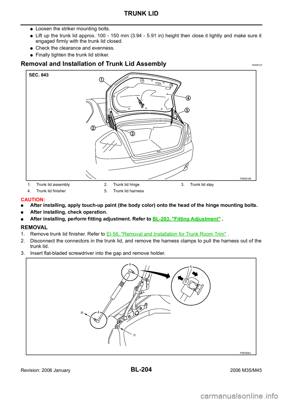
Removal and Installation of Trunk Lid AssemblyNIS001ZI
CAUTION:
After installing, apply touch-up paint (the body color) onto the head of the hinge mounting bolts.
After installing, check operation.
After installing, perform fitting adjustment. Refer to BL-203, "Fitting Adjustment" .
REMOVAL
1. Remove trunk lid finisher. Refer to EI-56, "Removal and Installation for Trunk Room Trim" .
2. Disconnect the connectors in the trunk lid, and remove the harness clamps to pull the harness out of the
trunk lid.
3. Insert flat-bladed screwdriver into the gap and remove holder.
1. Trunk lid assembly 2. Trunk lid hinge 3. Trunk lid stay
4. Trunk lid finisher 5. Trunk lid harness
PIIB5818E
PIIB3895J
Page 1186 of 5621

VEHICLE SECURITY (THEFT WARNING) SYSTEM
BL-247
C
D
E
F
G
H
J
K
L
MA
B
BL
Revision: 2006 January2006 M35/M45
Diagnostic Procedure 5NIS00209
VEHICLE SECURITY HEADLAMP ALARM CHECK
1. CHECK HEADLAMP OPERATION
Check if headlamp operate by lighting switch.
Does headlamp come on when turning switch
“ON”?
YES >> Headlamp circuit is OK.
NO >> Check headlamp system. Refer to LT- 4 3 , "
HEADLAMP (FOR USA) - XENON TYPE -" , LT- 8 ,
"HEADLAMP (FOR USA) - CONVENTIONAL TYPE -" or LT- 7 9 , "HEADLAMP (FOR CANADA) -
DAYTIME LIGHT SYSTEM -" .
Diagnostic Procedure 6NIS0020A
DOOR LOCK AND UNLOCK SWITCH CHECK
1. CHECK DOOR LOCK AND UNLOCK SWITCH INPUT SIGNAL
Check if power door lock operated by door lock and unlock switch.
Do doors lock / unlock when using each door lock and unlock switches?
YES >> Door lock and unlock switch is OK.
NO >> Check door lock and unlock switch. Refer to BL-36, "
Check Door Lock and Unlock Switch"
Diagnostic Procedure 7NIS0020B
VEHCLE SECURITY HAZARD LAMP ALARM CHECK
1. CHECK HAZARD WARNING LAMP
Does hazard warning lamp flash with hazard switch?
YES or NO
YES >> Hazard warning lamp circuit is OK.
NO >> Check hazard circuit. Refer to LT- 2 11 , "
TURN SIGNAL AND HAZARD WARNING LAMPS" .
Page 1213 of 5621

BL-274
IVIS (INFINITI VEHICLE IMMOBILIZER SYSTEM-NATS)
Revision: 2006 January2006 M35/M45
8. CHECK TURNING TIMING OF POWER SOURCE POSITION 2
Check all the Intelligent Keys for power source turning delay time after Push-button ignition switch is pushed
with Intelligent Key inserted into key slot. (Approx. 3 sec)
CAUTION:
Operate Push-button ignition switch without depressing the brake pedal.
No delay time exists>>GO TO 9.
Delay time exists when operated with particular Intelligent Key.>>Perform “C/U INITIALIZATION” referring to
CONSULT-II operation manual IVIS/NVIS NATS. In case that delay time still exists after the initial-
ization, replace the Intelligent Key.
Delay time exists when operated with any of the Intelligent Keys.>>Perform Trouble diagnosis symptom
chart 3. Refer to BL-180, "
Trouble Diagnosis Symptom Chart 3" .
9. CHECK ENGINE START FUNCTION
Check that engine can be started with Intelligent Key carried and inserted into the key slot respectively.
Engine can be started.>>GO TO 10.
Engine cannot be started.>>Inspect Trouble Diagnosis Flow Chart for IVIS (NATS). Refer to BL-275, "
Trou-
ble Diagnoses Flow Chart for IVIS (NATS)" .
10. CHECK SECURITY INDICATOR FUNCTION
Check Security Indicator for lighting up under the two conditions below.
Security Indicator lights off when Push-button ignition switch is pushed with Intelligent Key inserted into or
pulled out of the key slot.
Security Indicator blinks when Intelligent Key is pulled out and Push-button ignition switch is in lock posi-
tion.
Lighting up condition is normal.>>Inspection END.
Lighting up condition is malfunctioning.>>Perform Security Indicator Inspection. Refer to BL-277, "
Symptom
Chart for Security Indicator" .
Page 1221 of 5621

BL-282
INTEGRATED HOMELINK TRANSMITTER
Revision: 2006 January2006 M35/M45
Trouble DiagnosesNIS0020W
DIAGNOSTIC PROCEDURE
SYMPTOM: Transmitter does not activate receiver.
Before conducting the procedure given below, make sure that system receiver (garage door opener, etc.)
operates with original, hand-held transmitter. If NG, receiver or hand-held transmitter is malfunctioning, not
vehicle related.
1. ILLUMINATE CHECK
1. Turn ignition switch “OFF”.
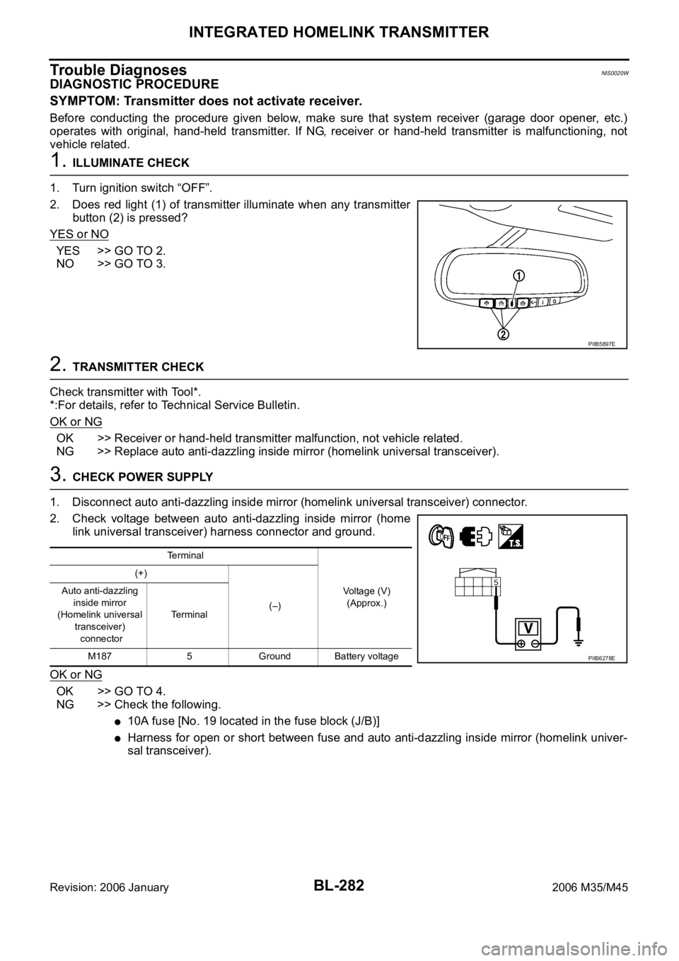
2. Does red light (1) of transmitter illuminate when any transmitter
button (2) is pressed?
YES or NO
YES >> GO TO 2.
NO >> GO TO 3.
2. TRANSMITTER CHECK
Check transmitter with Tool*.
*:For details, refer to Technical Service Bulletin.
OK or NG
OK >> Receiver or hand-held transmitter malfunction, not vehicle related.
NG >> Replace auto anti-dazzling inside mirror (homelink universal transceiver).
3. CHECK POWER SUPPLY
1. Disconnect auto anti-dazzling inside mirror (homelink universal transceiver) connector.
2. Check voltage between auto anti-dazzling inside mirror (home
link universal transceiver) harness connector and ground.
OK or NG
OK >> GO TO 4.
NG >> Check the following.
10A fuse [No. 19 located in the fuse block (J/B)]
Harness for open or short between fuse and auto anti-dazzling inside mirror (homelink univer-
sal transceiver).
PIIB5897E
Terminal
Voltage (V)
(Approx.) (+)
(–) Auto anti-dazzling
inside mirror
(Homelink universal
transceiver)
connectorTerminal
M187 5 Ground Battery voltage
PIIB6278E
Page 1251 of 5621

BL-312
BODY REPAIR
Revision: 2006 January2006 M35/M45
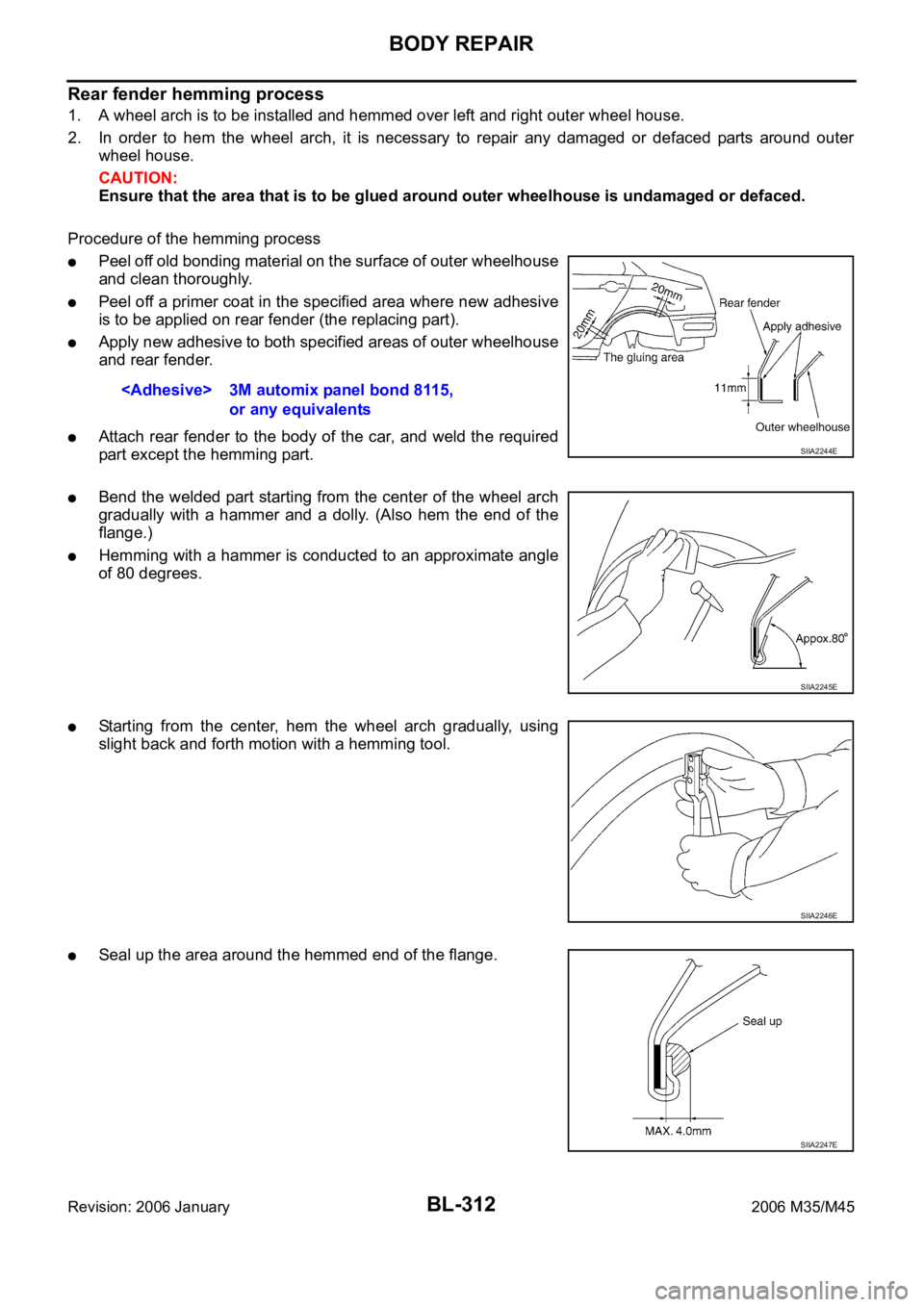
Rear fender hemming process
1. A wheel arch is to be installed and hemmed over left and right outer wheel house.
2. In order to hem the wheel arch, it is necessary to repair any damaged or defaced parts around outer
wheel house.
CAUTION:
Ensure that the area that is to be glued around outer wheelhouse is undamaged or defaced.
Procedure of the hemming process
Peel off old bonding material on the surface of outer wheelhouse
and clean thoroughly.
Peel off a primer coat in the specified area where new adhesive
is to be applied on rear fender (the replacing part).
Apply new adhesive to both specified areas of outer wheelhouse
and rear fender.
Attach rear fender to the body of the car, and weld the required
part except the hemming part.
Bend the welded part starting from the center of the wheel arch
gradually with a hammer and a dolly. (Also hem the end of the
flange.)
Hemming with a hammer is conducted to an approximate angle
of 80 degrees.
Starting from the center, hem the wheel arch gradually, using
slight back and forth motion with a hemming tool.
Seal up the area around the hemmed end of the flange.
or any equivalents
SIIA2244E
SIIA2245E
SIIA2246E
SIIA2247E
Page 1315 of 5621
![INFINITI M35 2006 Factory Workshop Manual BRC-4
[VDC/TCS/ABS]
PRECAUTIONS
Revision: 2006 January2006 M35/M45
Precautions for Brake ControlNFS000Q1
Just after starting vehicle after ignition switch ON, brake pedal may vibrate or motor operatin INFINITI M35 2006 Factory Workshop Manual BRC-4
[VDC/TCS/ABS]
PRECAUTIONS
Revision: 2006 January2006 M35/M45
Precautions for Brake ControlNFS000Q1
Just after starting vehicle after ignition switch ON, brake pedal may vibrate or motor operatin](/img/42/57023/w960_57023-1314.png)
BRC-4
[VDC/TCS/ABS]
PRECAUTIONS
Revision: 2006 January2006 M35/M45
Precautions for Brake ControlNFS000Q1
Just after starting vehicle after ignition switch ON, brake pedal may vibrate or motor operating noise may
be heard from engine compartment. This is normal condition.
When an error is indicated by ABS or another warning lamp, collect all necessary information from cus-
tomer (what symptoms are present under what conditions) and check for simple causes before starting
diagnostic servicing. Besides electrical system inspection, check brake booster operation, brake fluid
level, and oil leaks.
If tire size and type are used in an improper combination, or brake pads are not Genuine NISSAN parts,
stopping distance or steering stability may deteriorate.
ABS might be out of order or malfunctions by putting a radio (wiring inclusive), an antenna and a lead-in
wire near the control unit.
If aftermarket parts (car stereo, CD player, etc.) have been installed, check for incidents such as harness
pinches, open circuits, and improper wiring.
VDC system may not operate normally or a VDC OFF indicator lamp or SLIP indicator lamp may light.
–When replacing the following parts with parts other than genuine parts or making modifications: Suspen-
sion-related parts (shock absorber, spring, bushing, etc.), tires, wheels (other than specified sizes), brake-
related parts (pad, rotor, caliper, etc.), engine-related parts (muffler, ECM, etc.) and body reinforcement-
related parts (roll bar, tower bar, etc.).
–When driving with worn or deteriorated suspension, tires and brake-related parts.
Page 1319 of 5621
![INFINITI M35 2006 Factory Workshop Manual BRC-8
[VDC/TCS/ABS]
SYSTEM DESCRIPTION
Revision: 2006 January2006 M35/M45
from 4 wheel sensors. When ABS actuator and electric unit (control unit) detects a spin at drive wheels
(rear wheels), INFINITI M35 2006 Factory Workshop Manual BRC-8
[VDC/TCS/ABS]
SYSTEM DESCRIPTION
Revision: 2006 January2006 M35/M45
from 4 wheel sensors. When ABS actuator and electric unit (control unit) detects a spin at drive wheels
(rear wheels),](/img/42/57023/w960_57023-1318.png)
BRC-8
[VDC/TCS/ABS]
SYSTEM DESCRIPTION
Revision: 2006 January2006 M35/M45
from 4 wheel sensors. When ABS actuator and electric unit (control unit) detects a spin at drive wheels
(rear wheels), it compares wheel speed signals from all 4 wheels. At this time, LH and RH rear brake fluid
pressure are controlled, while fuel being cut to engine and throttle valve being closed to reduce engine
torque by the control unit. Further more, throttle position is continuously controlled to ensure the optimum
engine torque at all times.
During TCS operation, it informs driver of system operation by flashing SLIP indicator lamp.
Electrical system diagnosis by CONSULT-II is available.
VDC
Vehicle Dynamics Control system detects driver's steering operation amount and brake pedal travel from
steering angle sensor and pressure sensor. Using information from yaw rate/side G sensor and wheel
sensor, VDC judges driving condition (conditions of under steer and over steer) to improve vehicle driving
stability by controlling brake application to 4 wheels and engine output.
During VDC operation, it informs driver of system operation by flashing SLIP indicator lamp.
Electrical system diagnosis by CONSULT-II is available.
ECD
Receives deceleration degree commandment value signal from ICC sensor integrated unit, and controls brake
fluid pressure with the motor (built-in ABS actuator and electric unit (control unit)).
Operation That Is Not "System Error" NFS000Q7
ABS
When starting engine or just after starting vehicle, brake pedal may vibrate or the motor operating sound
may be heard from engine room. This is a normal states of the operation check.
During ABS operation, brake pedal lightly vibrates and a mechanical sound may be heard. This is normal.
Stopping distance may be longer than that of vehicles without ABS when vehicle drives on rough, gravel,
or snow-covered (fresh, deep snow) roads.
TCS
Depending on road circumstances, driver may have a sluggish feel. This is normal, because optimum
traction has highest priority under TCS operation.
When vehicle is passing through a road where surface friction varies, downshifting or depressing acceler-
ator pedal fully may activate TCS temporarily.
VDC
During VDC operation, body and brake pedal lightly vibrate and mechanical sounds may be heard. This is
normal.
If vehicle is rotated on turn table, or rolled and rocked on ship, ABS warning lamp, VDC OFF indicator
lamp, and SLIP indicator lamp may turn on. In this case, start engine on normal road again. If ABS warn-
ing lamp, VDC OFF indicator lamp, and SLIP indicator lamp turn off after restart, it is normal.
When starting TCS or VDC under rapid acceleration or hard turn, operating sound by brake pedal is gen-
erated. However, this is not malfunction. This is because TCS and VDC are functioning normally.
VDC may not operate normally or ABS warning lamp, VDC OFF indicator lamp and SLIP indicator lamp
may turn on when driving special roads with extremely steep slant (banks on circuit road and so on.) How-
ever, it is not malfunction when returning to a normal state after restarting the engine. In that case, be sure
to erase the memory of self-diagnosis. Refer to BRC-23, "
ERASE MEMORY" .
Yaw rate /side G sensor malfunction may occur under hard turn like spin turn, rapid acceleration turn, drift
run, etc., when VDC function is OFF (VDC OFF switch is turned on). It is not malfunction if it is possible to
return to a normal position after restarting engine. Then erase the memory of self-diagnosis. Refer to
BRC-23, "
ERASE MEMORY" .
VDC OFF indicator lamp and SLIP indicator lamp may simultaneously turn on when low tire pressure
warning lamp turns on. This is not a VDC system error but results from characteristic change of tires.
Fail-Safe FunctionNFS000Q8
ABS, EBD SYSTEM
In the event there is a malfunction with the electrical system, the ABS warning lamp, VDC OFF indicator lamp,
and SLIP indicator lamp will turn on when it is the ABS that is malfunctioning, and the brake warning lamp,
ABS warning lamp, VDC OFF indicator lamp, and SLIP indicator lamp will turn on when it is the EBD that is
Page 1343 of 5621
![INFINITI M35 2006 Factory Workshop Manual BRC-32
[VDC/TCS/ABS]
TROUBLE DIAGNOSIS
Revision: 2006 January2006 M35/M45
For Fast and Accurate DiagnosisNFS000QJ
PRECAUTIONS FOR DIAGNOSIS
Before performing diagnosis, always read General Information INFINITI M35 2006 Factory Workshop Manual BRC-32
[VDC/TCS/ABS]
TROUBLE DIAGNOSIS
Revision: 2006 January2006 M35/M45
For Fast and Accurate DiagnosisNFS000QJ
PRECAUTIONS FOR DIAGNOSIS
Before performing diagnosis, always read General Information](/img/42/57023/w960_57023-1342.png)
BRC-32
[VDC/TCS/ABS]
TROUBLE DIAGNOSIS
Revision: 2006 January2006 M35/M45
For Fast and Accurate DiagnosisNFS000QJ
PRECAUTIONS FOR DIAGNOSIS
Before performing diagnosis, always read General Information (GI) to confirm general precautions. Refer
to GI-4, "
General Precautions" .
If steering angle sensor, steering system parts, suspension system parts, ABS actuator and electric unit
(control unit) or tires have been replaced, or if wheel alignment has been adjusted, be sure to adjust neu-
tral position of steering angle sensor before driving. Refer to BRC-6, "
Adjustment of Steering Angle Sen-
sor Neutral Position" .
After diagnosis is finished, be sure to erase memory. Refer to BRC-23, "ERASE MEMORY" .
When checking continuity and voltage between unit, be sure to check for disconnection, looseness, bend,
or collapse of connector terminals. If any malfunction is found, repair or replace connector terminals.
For intermittent symptoms, possible cause is malfunction in harness, harness connector, or terminals.
Move harness, harness connector, and terminals to check for poor connections.
If a circuit tester is used for the check, be careful not to forcibly extend any connector terminal.
The following symptoms may be caused by normal operations.
Symptom Symptom description Result
Motor operation soundThis is sound of motor inside VDC actuator. Slight sound may occur
during VDC, TCS, and ABS operation.
Normal
Just after engine starts, the motor operating sound may be heard. This
is a normal condition of the system operation check.
System operation check
soundWhen engine starts, slight “click” sound may be heard from engine
room. This is normal and is part of system operation check.Normal
VDC/TCS operation
(SLIP indicator lamp ON)TCS may activate momentarily if wheel speed changes when driving
over location where friction varies, when downshifting, or when fully
depressing accelerator pedal.Normal
Cancel the VDC/TCS
function for the
inspection on a chas-
sis dynamometer. When checking speed meter etc. with a 2-wheel-drive chassis dyna-
mometer, vehicle speed is not increased by pressing down on the accel-
erator.
ABS operation (Longer stop-
ping distance)On roads with low friction, such as snowy roads or gravel roads, vehi-
cles with ABS may require a longer stopping distance. Therefore, when
driving on such roads, avoid overconfidence and keep speed sufficiently
low.Normal
Insufficient feeling of accel-
erationDepending on road conditions, driver may feel that feeling of accelera-
tion is insufficient. This is because traction control, which controls
engine and brakes to achieve optimal traction, has the highest priority
(for safety). As a result, there may be times when acceleration is slightly
less than usual for the same accelerator pedal operation.Normal
Page 1366 of 5621
![INFINITI M35 2006 Factory Workshop Manual TROUBLE DIAGNOSIS
BRC-55
[VDC/TCS/ABS]
C
D
E
G
H
I
J
K
L
MA
B
BRC
Revision: 2006 January2006 M35/M45
Symptom 3 The Braking Distance Is LongNFS000R6
CAUTION:
The stopping distance on slippery road INFINITI M35 2006 Factory Workshop Manual TROUBLE DIAGNOSIS
BRC-55
[VDC/TCS/ABS]
C
D
E
G
H
I
J
K
L
MA
B
BRC
Revision: 2006 January2006 M35/M45
Symptom 3 The Braking Distance Is LongNFS000R6
CAUTION:
The stopping distance on slippery road](/img/42/57023/w960_57023-1365.png)
TROUBLE DIAGNOSIS
BRC-55
[VDC/TCS/ABS]
C
D
E
G
H
I
J
K
L
MA
B
BRC
Revision: 2006 January2006 M35/M45
Symptom 3 The Braking Distance Is LongNFS000R6
CAUTION:
The stopping distance on slippery road surfaces might be longer with the ABS operating than when
the ABS is not operating.
1. CHECK FUNCTION
Turn ignition switch OFF and disconnect ABS actuator and electric unit (control unit) connector to deactivate
ABS. In this condition, check stopping distance. After inspection, connect connector.
OK or NG
OK >> GO TO procedure 3 “CHECK WHEEL SENSOR AND SENSOR ROTOR” of symptom 1. Refer to
BRC-53, "
Symptom 1 Excessive ABS Function Operation Frequency" .
NG >> Check brake system.
Symptom 4 ABS Function Does Not OperateNFS000R7
CAUTION:
ABS does not operate when speed is 10 km/h (6 MPH) or lower.
1. CHECK ABS WARNING LAMP DISPLAY
Make sure that the ABS warning lamp turns OFF after ignition switch is turned on or when driving.
OK or NG
OK >> GO TO procedure 3 “CHECK WHEEL SENSOR AND SENSOR ROTOR” of symptom 1. Refer to
BRC-53, "
Symptom 1 Excessive ABS Function Operation Frequency" .
NG >> Perform self-diagnosis. Refer to BRC-23, "
Self-Diagnosis" .
Symptom 5 Pedal Vibration or ABS Operation Sound OccursNFS000R8
CAUTION:
Under the following conditions, ABS is activated and vibration is felt when brake pedal is lightly
depressed (just place a foot on it).However, this is normal.
When shifting gears
When driving on slippery road
During cornering at high speed
When passing over bumps or grooves [at approximately 50 mm (1.97 in) or more]
When pulling away just after starting engine [at approximately 10 km/h (6 MPH) or higher]
1. SYMPTOM CHECK 1
Check if there is pedal vibration or operation sound when the engine is started.
Do symptoms occur?
YES >> GO TO 2.
NO >> Perform self -diagnosis. Refer to BRC-23, "
Self-Diagnosis" .
2. SYMPTOM CHECK 2
Check symptoms when electrical component (headlamps, etc.) switches are operated.
Do symptoms occur?
YES >> Check if there is a radio, antenna, antenna lead wire, or wiring close to the control unit. If there is,
move it farther away.
NO >> GO TO procedure 3 “CHECK WHEEL SENSOR AND SENSOR ROTOR” of symptom 1. Refer to
BRC-53, "
Symptom 1 Excessive ABS Function Operation Frequency" .
Page 1378 of 5621
![INFINITI M35 2006 Factory Workshop Manual PRECAUTIONS
CO-3
[VQ35DE]
C
D
E
F
G
H
I
J
K
L
MA
CO
Revision: 2006 January2006 M35/M45
[VQ35DE]PRECAUTIONSPFP:00001
Precautions for Supplemental Restraint System (SRS) “AIR BAG” and “SEAT
BELT INFINITI M35 2006 Factory Workshop Manual PRECAUTIONS
CO-3
[VQ35DE]
C
D
E
F
G
H
I
J
K
L
MA
CO
Revision: 2006 January2006 M35/M45
[VQ35DE]PRECAUTIONSPFP:00001
Precautions for Supplemental Restraint System (SRS) “AIR BAG” and “SEAT
BELT](/img/42/57023/w960_57023-1377.png)
PRECAUTIONS
CO-3
[VQ35DE]
C
D
E
F
G
H
I
J
K
L
MA
CO
Revision: 2006 January2006 M35/M45
[VQ35DE]PRECAUTIONSPFP:00001
Precautions for Supplemental Restraint System (SRS) “AIR BAG” and “SEAT
BELT PRE-TENSIONER”
NBS005RT
The Supplemental Restraint System such as “AIR BAG” and “SEAT BELT PRE-TENSIONER”, used along
with a front seat belt, helps to reduce the risk or severity of injury to the driver and front passenger for certain
types of collision. This system includes seat belt switch inputs and dual stage front air bag modules. The SRS
system uses the seat belt switches to determine the front air bag deployment, and may only deploy one front
air bag, depending on the severity of a collision and whether the front occupants are belted or unbelted.
Information necessary to service the system safely is included in the SRS and SB section of this Service Man-
ual.
WAR NING :
To avoid rendering the SRS inoperative, which could increase the risk of personal injury or death
in the event of a collision which would result in air bag inflation, all maintenance must be per-
formed by an authorized NISSAN/INFINITI dealer.
Improper maintenance, including incorrect removal and installation of the SRS, can lead to per-
sonal injury caused by unintentional activation of the system. For removal of Spiral Cable and Air
Bag Module, see the SRS section.
Do not use electrical test equipment on any circuit related to the SRS unless instructed to in this
Service Manual. SRS wiring harnesses can be identified by yellow and/or orange harnesses or
harness connectors.
Precautions for Liquid GasketNBS004QK
REMOVAL OF LIQUID GASKET SEALING
After removing mounting nuts and bolts, separate the mating
surface using the seal cutter (SST) and remove old liquid gasket
sealing.
CAUTION:
Be careful not to damage the mating surfaces.
Tap the seal cutter to insert it, and then slide it by tapping on the
side as shown in the figure.
In areas where seal cutter is difficult to use, use a plastic ham-
mer to lightly tap the parts, to remove it.
CAUTION:
If for some unavoidable reason tool such as a screwdriver
is used, be careful not to damage the mating surfaces.
LIQUID GASKET APPLICATION PROCEDURE
1. Using a scraper, remove old liquid gasket adhering to the liquid
gasket application surface and the mating surface.
Remove liquid gasket completely from the groove of the liquid
gasket application surface, mounting bolts, and bolt holes.
2. Wipe the liquid gasket application surface and the mating sur-
face with white gasoline (lighting and heating use) to remove
adhering moisture, grease and foreign materials.
PBIC0002E
PBIC0003E