release fuel pressure INFINITI M35 2006 Factory Workshop Manual
[x] Cancel search | Manufacturer: INFINITI, Model Year: 2006, Model line: M35, Model: INFINITI M35 2006Pages: 5621, PDF Size: 65.56 MB
Page 3417 of 5621
FL-4
FUEL LEVEL SENSOR UNIT, FUEL FILTER AND FUEL PUMP ASSEMBLY
Revision: 2006 January2006 M35/M45
FUEL LEVEL SENSOR UNIT, FUEL FILTER AND FUEL PUMP ASSEMBLYPFP:17042
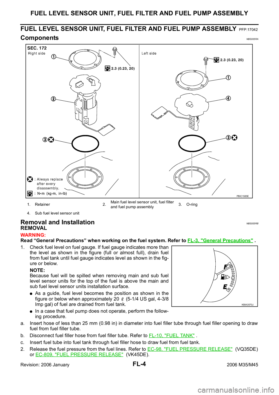
ComponentsNBS005RA
Removal and InstallationNBS005RB
REMOVAL
WAR NING :
Read “General Precautions” when working on the fuel system. Refer to FL-3, "
General Precautions" .
1. Check fuel level on fuel gauge. If fuel gauge indicates more than
the level as shown in the figure (full or almost full), drain fuel
from fuel tank until fuel gauge indicates level as shown in the fig-
ure or below.
NOTE:
Because fuel will be spilled when removing main and sub fuel
level sensor units for the top of the fuel is above the main and
sub fuel level sensor units installation surface.
As a guide, fuel level becomes the position as shown in the
figure or below when approximately 20 (5-1/4 US gal, 4-3/8
Imp gal) of fuel are drained from fuel tank.
In a case that fuel pump does not operate, perform the follow-
ing procedure.
a. Insert hose of less than 25 mm (0.98 in) in diameter into fuel filler tube through fuel filler opening to draw
fuel from fuel filler tube.
b. Disconnect fuel filler hose from fuel filler tube. Refer to FL-10, "
FUEL TANK" .
c. Insert fuel tube into fuel tank through fuel filler hose to draw fuel from fuel tank.
2. Release the fuel pressure from the fuel lines. Refer to EC-98, "
FUEL PRESSURE RELEASE" (VQ35DE)
or EC-809, "
FUEL PRESSURE RELEASE" (VK45DE).
1. Retainer 2.Main fuel level sensor unit, fuel filter
and fuel pump assembly3. O-ring
4. Sub fuel level sensor unit
PBIC1585E
KBIA3570J
Page 3418 of 5621
FUEL LEVEL SENSOR UNIT, FUEL FILTER AND FUEL PUMP ASSEMBLY
FL-5
C
D
E
F
G
H
I
J
K
L
MA
FL
Revision: 2006 January2006 M35/M45
3. Open fuel filler lid.
4. Open filler cap and release the pressure inside fuel tank.
5. Remove rear seat cushion. Refer to SE-172, "
REAR SEAT" .
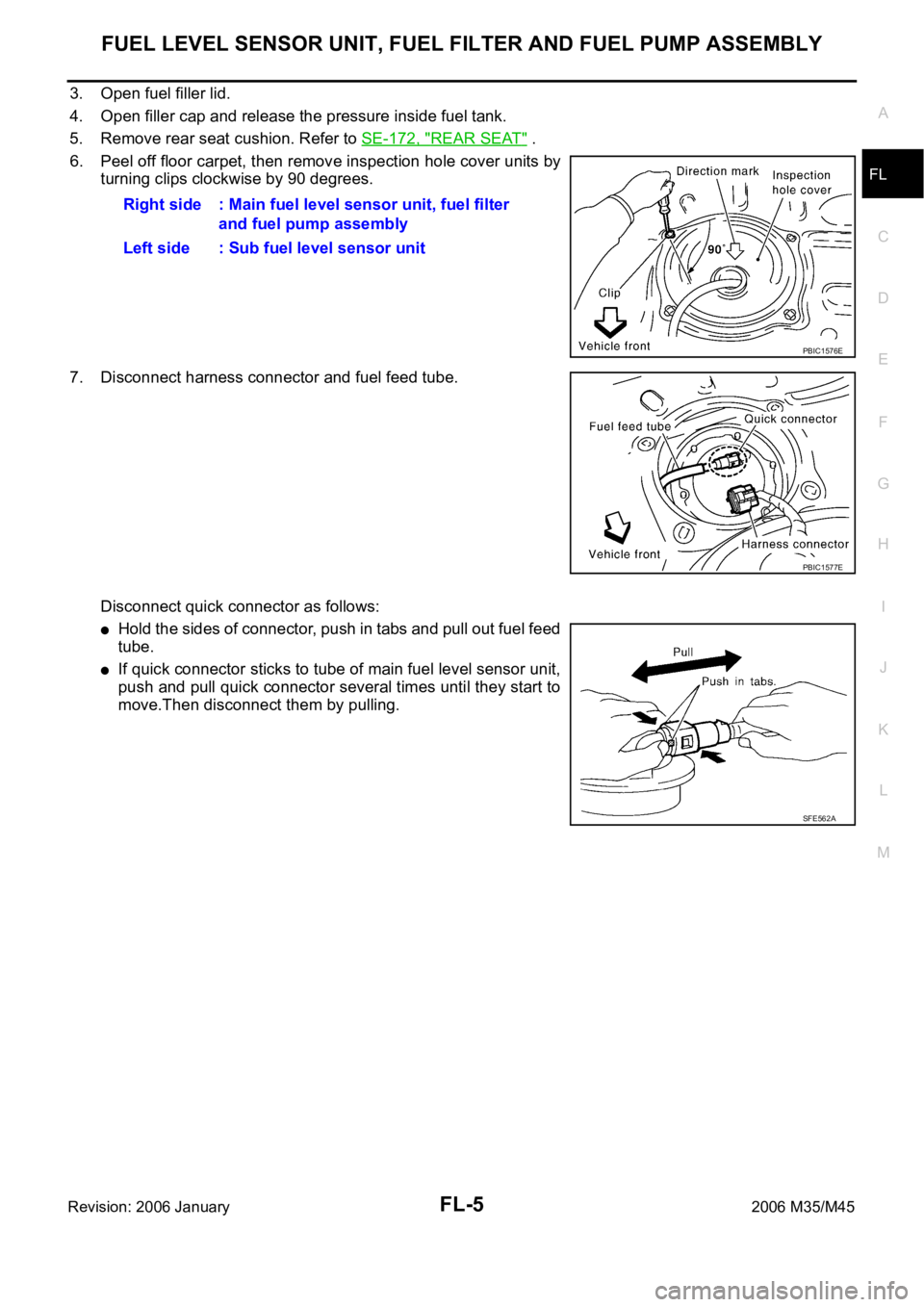
6. Peel off floor carpet, then remove inspection hole cover units by
turning clips clockwise by 90 degrees.
7. Disconnect harness connector and fuel feed tube.
Disconnect quick connector as follows:
Hold the sides of connector, push in tabs and pull out fuel feed
tube.
If quick connector sticks to tube of main fuel level sensor unit,
push and pull quick connector several times until they start to
move.Then disconnect them by pulling.Right side : Main fuel level sensor unit, fuel filter
and fuel pump assembly
Left side : Sub fuel level sensor unit
PBIC1576E
PBIC1577E
SFE562A
Page 3470 of 5621
PRECAUTIONS
GI-7
C
D
E
F
G
H
I
J
K
L
MB
GI
Revision: 2006 January2006 M35/M45
(i.e. Flexible Fuel Vehicle - FFV models). Using a fuel other than that specified could adversely affect
the emission control devices and systems, and could also affect the warranty coverage validity.
Precautions for Multiport Fuel Injection System or Engine Control SystemNAS0007C
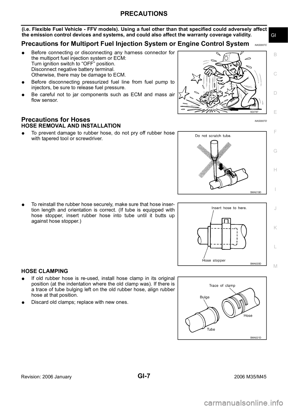
Before connecting or disconnecting any harness connector for
the multiport fuel injection system or ECM:
Turn ignition switch to “OFF” position.
Disconnect negative battery terminal.
Otherwise, there may be damage to ECM.
Before disconnecting pressurized fuel line from fuel pump to
injectors, be sure to release fuel pressure.
Be careful not to jar components such as ECM and mass air
flow sensor.
Precautions for HosesNAS0007D
HOSE REMOVAL AND INSTALLATION
To prevent damage to rubber hose, do not pry off rubber hose
with tapered tool or screwdriver.
To reinstall the rubber hose securely, make sure that hose inser-
tion length and orientation is correct. (If tube is equipped with
hose stopper, insert rubber hose into tube until it butts up
against hose stopper.)
HOSE CLAMPING
If old rubber hose is re-used, install hose clamp in its original
position (at the indentation where the old clamp was). If there is
a trace of tube bulging left on the old rubber hose, align rubber
hose at that position.
Discard old clamps; replace with new ones.
SGI787
SMA019D
SMA020D
SMA021D
Page 3645 of 5621

IDX-4
ALPHABETICAL INDEX
Electronic ignition (EI) system ............. EC-33, EC-743
Engine control module (ECM) .......... EC-496, EC-1215
Engine control system diagram ........... EC-30, EC-740
Engine coolant temperature sensor (ECTS) ... EC-226,
EC-238
, EC-948, EC-961
Engine coolant(VK45DE) .................................. CO-40
Engine coolant(VQ35DE) ................................. CO-11
Engine oil filter replacement ............................. MA-26
Engine oil filter replacement(VQ35DE) ............. MA-19
Engine oil precautions .......................................... GI-8
Engine oil replacement(VQ35DE) ..................... MA-18
Engine oil(VK45DE) ........................................... LU-26
Engine oil(VQ35DE) ............................................ LU-7
Engine removal(VK45DE) ............................... EM-244
Engine removal(VQ35DE) .............................. EM-113
Engine room cover ............................................ EM-14
Engine room cover(VK45DE) ......................... EM-173
ETC1 - Wiring diagram .................... EC-614, EC-1345
ETC2 - Wiring diagram .................... EC-609, EC-1340
ETC3 - Wiring diagram .................... EC-620, EC-1352
EVAP canister ...................................... EC-42, EC-752
EVAP canister purge volume control solenoid valve ....
EC-412
, EC-420, EC-1132, EC-1140
EVAP canister vent control valve ...... EC-427, EC-434,
EC-1147
, EC-1154
EVAP control system (small leak) diagnosis .. EC-403,
EC-466
, EC-1124, EC-1185
EVAP control system pressure sensor ........... EC-440,
EC-443
, EC-450, EC-1160, EC-1163, EC-1170
EVAP control system purge flow monitoring diagnosis
EC-398
, EC-1119
EVAP vapor lines inspection ................. MA-21, MA-28
Evaporative emission (EVAP) system . EC-39, EC-749
Evaporator ..................................................... ATC-168
Exhaust manifold(VK45DE) ............................ EM-183
Exhaust system ................................................... EX-3
Exhaust system inspection ..................... EX-3, MA-29
Expansion valve ............................................. ATC-169
F
F/FOG - Wiring diagram ................................... LT-197
F/PUMP - Wiring diagram ................ EC-686, EC-1428
Final drive pre-inspection .................. FFD-16, RFD-19
Final drive removal and installation .. FFD-13, RFD-16
Floor trim ............................................................. EI-50
Flow charts ......................................................... GI-28
Fluid temperature sensor (A/T) ........................ AT-135
Fluorescent leak detector .............................. ATC-170
FPCM - Wiring diagram ................... EC-527, EC-1253
Freeze frame data ............................... EC-59, EC-770
Front brake solenoid valve ................. AT-151, AT-153
Front bumper ...................................................... EI-11
Front combination lamp removal and installation LT-76
Front door ............................. BL-190, BL-196, GW-63
Front passenger air bag .................................. SRS-42
Front seat belt .................................................... SB-30
Front seat belt pre-tensioner ..... SB-2, SRS-3, SRS-47
Front washer ...................................................... WW-4
Front wiper ......................................................... WW-4
FTS - Wiring diagram ....................................... AT-136
FTTS - Wiring diagram .... EC-345, EC-350, EC-1068,
EC-1073
Fuel cut control (at no load high engine speed) EC-34,
EC-744
Fuel filter replacement ......................................... FL-4
Fuel gauge ............................................................ DI-5
Fuel injection system (Bank 1) ......... EC-321, EC-332,
EC-1044
, EC-1055
Fuel injection system (Bank 2) ......... EC-321, EC-332,
EC-1044
, EC-1055
Fuel injector ................................................... EC-1420
Fuel injector and fuel tube(VK45DE) .............. EM-193
Fuel injector and fuel tube(VQ35DE) ................ EM-45
Fuel level sensor EC-475, EC-477, EC-479, EC-1194,
EC-1196
, EC-1198
Fuel line inspection .................................. FL-3, MA-25
Fuel line inspection(VQ35DE) .......................... MA-18
Fuel precautions ................................................... GI-6
Fuel pressure check ........................... EC-98, EC-809
Fuel pressure release ......................... EC-98, EC-809
Fuel pump ....................................... EC-685, EC-1427
Fuel pump and gauge .......................................... FL-4
Fuel pump control module .............. EC-525, EC-1251
Fuel pump dropping resistor ........... EC-525, EC-1251
Fuel system ......................................................... FL-3
Fuel tank ............................................................ FL-10
Fuel tank temperature sensor .......... EC-343, EC-349,
EC-1066
, EC-1072
Fuel tank vacuum relief valve ............. EC-42, EC-752
FUELB1 - Wiring diagram EC-323, EC-334, EC-1046,
EC-1057
FUELB2 - Wiring diagram EC-325, EC-336, EC-1048,
EC-1059
Fuse .................................................................. PG-17
Fuse and fusible link box ................................ PG-112
Fusible link ........................................................ PG-17
G
Gauges ................................................................. DI-5
Generator ........................................................... SC-23
Generator - See Alternator ................................ SC-23
Glass ........................ GW-11, GW-61, GW-63, GW-67
Grille - See Exterior ............................................ EI-16
Ground distribution ........................................... PG-46
H
H/LAMP - Wiring diagram ....................... LT-13
, LT-48
Harness connector .......................................... PG-102
Harness layout .................................................. PG-63
Hazard warning lamp ....................................... LT-211
Headlamp removal and installation .................... LT-76
Headlining - See Roof trim .................................. EI-52
Heated oxygen sensor 2 (bank 1) .... EC-286, EC-297,
EC-310
, EC-1009, EC-1020, EC-1033
Heated oxygen sensor 2 (bank 2) .... EC-286, EC-297,
Page 5152 of 5621
STARTING SYSTEM
SC-15
C
D
E
F
G
H
I
J
L
MA
B
SC
Revision: 2006 January2006 M35/M45
DIAGNOSTIC PROCEDURE 1
Check “B” Terminal Circuit
CAUTION:
Perform diagnosis under the condition that engine cannot start by the following procedure.
1. Remove fuel pump fuse.
2. Crank or start the engine (where possible) until the fuel pressure is released.
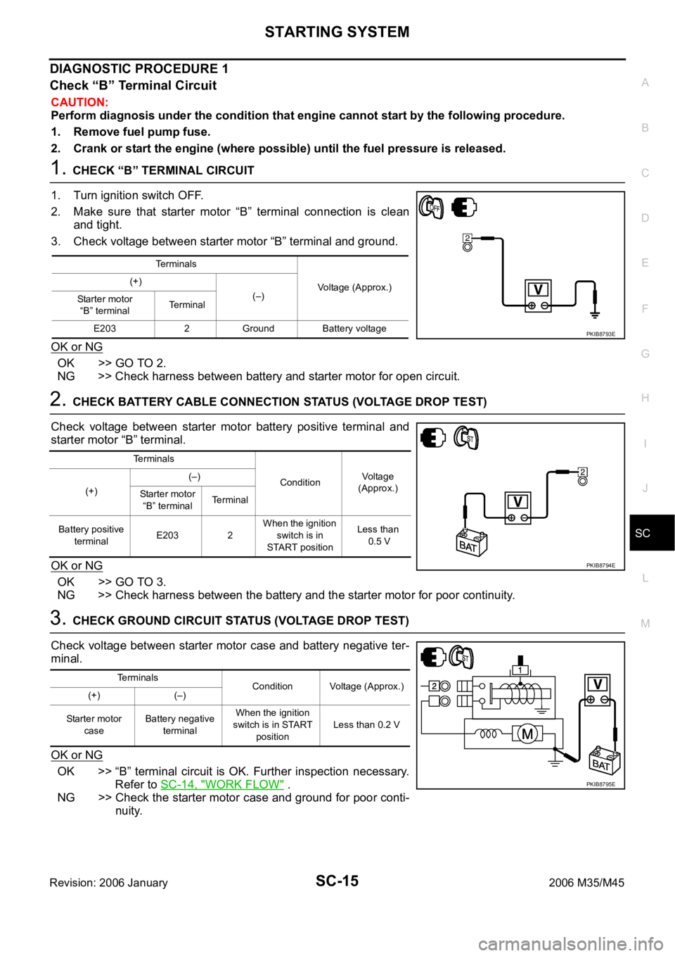
1. CHECK “B” TERMINAL CIRCUIT
1. Turn ignition switch OFF.
2. Make sure that starter motor “B” terminal connection is clean
and tight.
3. Check voltage between starter motor “B” terminal and ground.
OK or NG
OK >> GO TO 2.
NG >> Check harness between battery and starter motor for open circuit.
2. CHECK BATTERY CABLE CONNECTION STATUS (VOLTAGE DROP TEST)
Check voltage between starter motor battery positive terminal and
starter motor “B” terminal.
OK or NG
OK >> GO TO 3.
NG >> Check harness between the battery and the starter motor for poor continuity.
3. CHECK GROUND CIRCUIT STATUS (VOLTAGE DROP TEST)
Check voltage between starter motor case and battery negative ter-
minal.
OK or NG
OK >> “B” terminal circuit is OK. Further inspection necessary.
Refer to SC-14, "
WORK FLOW" .
NG >> Check the starter motor case and ground for poor conti-
nuity.
Terminals
Voltage (Approx.) (+)
(–)
Starter motor
“B” terminalTerminal
E203 2 Ground Battery voltage
PKIB8793E
Terminals
ConditionVoltage
(Approx.)
(+)(–)
Starter motor
“B” terminalTerminal
Battery positive
terminalE203 2 When the ignition
switch is in
START positionLess than
0.5 V
PKIB8794E
Terminals
Condition Voltage (Approx.)
(+) (–)
Starter motor
caseBattery negative
terminalWhen the ignition
switch is in START
positionLess than 0.2 V
PKIB8795E
Page 5153 of 5621
SC-16
STARTING SYSTEM
Revision: 2006 January2006 M35/M45
DIAGNOSTIC PROCEDURE 2
Check “S” Connector Circuit
CAUTION:
Perform diagnosis under the condition that engine cannot start by the following procedure.
1. Remove fuel pump fuse.
2. Crank or start the engine (where possible) until the fuel pressure is released.
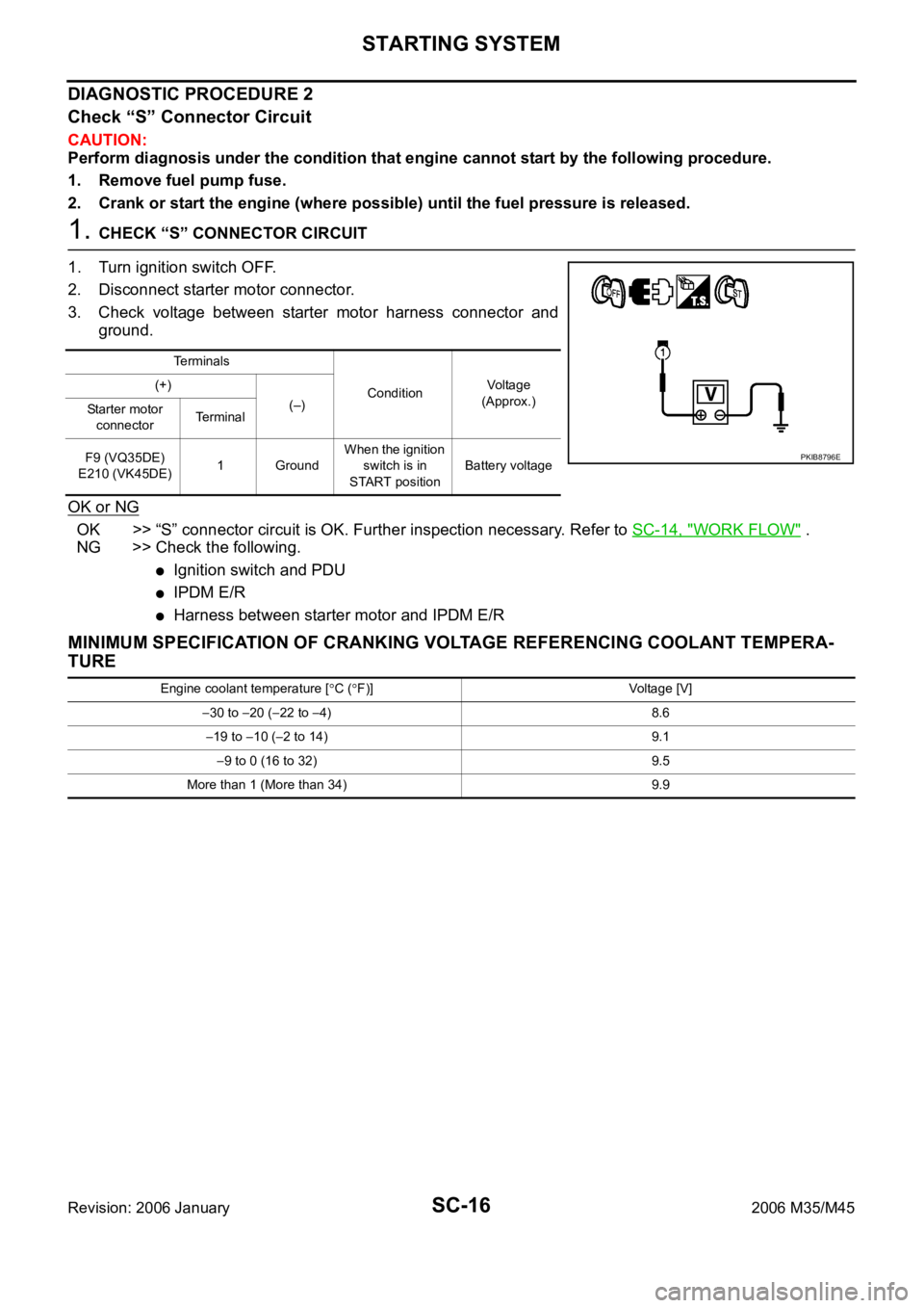
1. CHECK “S” CONNECTOR CIRCUIT
1. Turn ignition switch OFF.
2. Disconnect starter motor connector.
3. Check voltage between starter motor harness connector and
ground.
OK or NG
OK >> “S” connector circuit is OK. Further inspection necessary. Refer to SC-14, "WORK FLOW" .
NG >> Check the following.
Ignition switch and PDU
IPDM E/R
Harness between starter motor and IPDM E/R
MINIMUM SPECIFICATION OF CRANKING VOLTAGE REFERENCING COOLANT TEMPERA-
TURE
Te r m i n a l s
ConditionVoltage
(Approx.) (+)
(–)
Starter motor
connectorTe r m i n a l
F9 (VQ35DE)
E210 (VK45DE)1 GroundWhen the ignition
switch is in
START positionBattery voltage
PKIB8796E
Engine coolant temperature [C (F)] Voltage [V]
30 to 20 (22 to 4) 8.6
19 to 10 (2 to 14) 9.1
9 to 0 (16 to 32) 9.5
More than 1 (More than 34) 9.9