check engine light INFINITI M35 2006 Factory Repair Manual
[x] Cancel search | Manufacturer: INFINITI, Model Year: 2006, Model line: M35, Model: INFINITI M35 2006Pages: 5621, PDF Size: 65.56 MB
Page 4587 of 5621

LT-160
ACTIVE AFS
Revision: 2006 January2006 M35/M45
ACTIVE TEST
Operation Procedure
1. Start the engine. (Swivel actuator is initialized.)
2. Touch “ADAPTIVE LIGHT” on “SELECT SYSTEM” screen.
3. Touch “ACTIVE TEST” on “SELECT DIAG MODE” screen.
4. Touch “LOW BEAM TEST RIGHT”, “LOW BEAM TEST LEFT”, or “LEVELIZER TEST” on “SELECT TEST
ITEM” screen.
CAUTION:
Can be tested only when swivel actuator initialization is completed. If initialization is not com-
pleted, “RETRY COMMAND” is displayed and cannot be tested.
LOW BEAM TEST RIGHT
Low beam headlamp (right) can be operated to swivel angle
0
by touching “ORIGIN”, and to maximum angle by “PEAK”.
LOW BEAM TEST LEFT
Low beam headlamp (left) can be operated to swivel angle 0
by touching “ORIGIN”, and to maximum angle by “PEAK”.
LEVELIZER TEST
Aiming motor drive signal can be changed to approx. 85%
(ratio to IGN power supply) by touching “ORIGIN”, and to
approx. 15% by “PEAK”. That angles headlamp LO up and
down.
5. During the operation check, touching “BACK” deactivates the operation.
Test Item Swivel Speed Mode
ORIGIN/PEAK - FAST Three times fast as SLOW Normal operation
ORIGIN/PEAK - SLOW — Initialization
SKIB4794E
Test Item Swivel Speed Mode
ORIGIN/PEAK - FAST Three times fast as SLOW Normal operation
ORIGIN/PEAK - SLOW — Initialization
SKIB4795E
Test ItemAiming Motor Drive Signal
Light Axis
(Reference Value) Ratio to IGN
power supplyVoltage
ORIGIN Approx. 85% Approx. 10.6 V 0
PEAK Approx. 15% Approx. 1.9 VApprox. 2.5
(Relatively lower than
that of origin)SKIB4796E
Page 4588 of 5621

ACTIVE AFS
LT-161
C
D
E
F
G
H
I
J
L
MA
B
LT
Revision: 2006 January2006 M35/M45
Symptom ChartNKS003QN
CAUTION:
The low beam headlamps performs small movements when AFS control unit detects the engine start.
This is normal with initialization of swivel actuator by AFS control unit.
SymptomAFS OFF
indicatorCausal system Reference
AFS operates, but cannot judge normal/
abnormal.
(AFS function test)NormalCheck swivel operation.LT-181, "AFS
Operation
Check (Func-
tion Test)"
Check steering angle sensor neutral point (straight-ahead
position).
Auto aiming operates, but cannot judge
normal/abnormal.
(Auto aiming function test)NormalCheck auto aiming operation.LT-183, "Auto
Aiming Opera-
tion Check
(Function
Te s t )"
Check height sensor signal value recognized by AFS con-
trol unit at unloaded vehicle position.
Check height sensor signal and aiming motor drive signal.
Neither AFS operates nor auto aiming
operates.BlinkingCheck AFS control unit self-diagnostic results. LT-154,
"SELF-DIAG
RESULTS"
Check AFS control unit power supply and ground circuit.
NOTE:
Check only when “ADAPTIVE LIGHT” is not displayed on
CONSULT-II “SELECT SYSTEM” screen.LT-151, "Pre-
liminary
Check"
AFS does not operate.
(Auto aiming operation is normal.)Blinking Check AFS control unit self-diagnostic results. LT-154,
"SELF-DIAG
RESULTS"
Illuminated Check AFS switch system circuit.LT-185, "
AFS
Switch Does
Not Operate"
Auto aiming does not operate.
(AFS operation is normal.)NormalCheck AFS control unit self-diagnostic results. LT-154,
"SELF-DIAG
RESULTS"
Check aiming motor system circuit.LT-187, "
Auto
Aiming Does
Not Operate
(Check Aiming
Motor System
Circuit)"
Auto aiming operates in the reverse way.
(Lowering vehicle height angles light
axis up.)Normal Replace AFS control unit.LT-191, "Removal and
Installation of
AFS Control
Unit"
AFS OFF indicator does not illuminate.
(AFS operation and auto aiming opera-
tion are normal.)Not
illuminatedCheck circuit between unified meter and A/C amp. and
combination meter.LT-190, "
AFS
OFF Indicator
Does Not
Operate"AFS OFF indicator blinks.
(AFS operation and auto aiming opera-
tion are normal.)BlinkingCheck receive state of AFS off indicator signal from uni-
fied meter and A/C amp.
AFS cannot be cancelled.
(AFS switch does not operate.)Normal Check AFS switch system circuit.LT-185, "AFS
Switch Does
Not Operate"
Page 4608 of 5621

ACTIVE AFS
LT-181
C
D
E
F
G
H
I
J
L
MA
B
LT
Revision: 2006 January2006 M35/M45
AFS Operation Check (Function Test)NKS003QS
1. CHECK SWIVEL ACTUATOR
1. Start engine and turn lighting switch to 2ND position.
2. Select “ADAPTIVE LIGHT” on CONSULT-II. Select “ACTIVE
TEST” on “SELECT DIAG MODE” screen.
3. Select “LOW BEAM TEST RIGHT” or “LOW BEAM TEST LEFT”
on “SELECT TEST ITEM” screen.
4. Touch “ORIGIN–FAST/SLOW” and “PEAK–FAST/SLOW”
screen.
5. Make sure of swivel operation.
OK or NG
OK >> GO TO 2.
NG >>
When interference or poor fitment is found, perform aiming adjustment. Refer to LT- 7 4 , "Aiming
Adjustment" . If it is normal, replace headlamp. Refer to LT- 1 9 0 , "Removal and Installation of
Front Combination Lamp" .
When the operation range is irregular, perform aiming adjustment. Refer to LT- 7 4 , "Aiming
Adjustment" . If it is normal, GO TO 3.
2. CHECK STEERING ANGLE SENSOR
Check “STR ANGLE SIG” in “Data Monitor” when driving straight
and steering turn 90
to right or left.
OK or NG
OK >> GO TO 3.
NG >>
When steering is out of range while driving straight, perform steering angle sensor adjustment.
Refer to BRC-6, "
Adjustment of Steering Angle Sensor Neutral Position" in “ON-VEHICLE
SERVICE”.
When the function is normal while driving straight but the displayed value is different from
actual steering position with turning to right or left, replace steering angle sensor. Refer to LT-
190, "Removal and Installation of Steering Angle Sensor" .
SKIB4794E
TEST ITEM ORIGIN PEAKLight axis range at 10 m (394.7 in) off
(Reference value)
LOW BEAM TEST RIGHT Swivel angle 0
Swivel angle 7 to 13Approx. 1.200 to 2.300 mm (48 to 90 in)
LOW BEAM TEST LEFT Swivel angle 0
Swivel angle 17 to 23Approx. 3.000 to 4.200 mm (120 to 167 in)
Steering conditionSTR ANGLE SIG
(Data monitor)
Driving straight
5.0 to + 5.0
Turn 90 to right Approx. + 90
Tu rn 90 to left Approx. 90
SKIB4793E
Page 4610 of 5621

ACTIVE AFS
LT-183
C
D
E
F
G
H
I
J
L
MA
B
LT
Revision: 2006 January2006 M35/M45
Auto Aiming Operation Check (Function Test)NKS003QT
1. CHECK AIMING MOTOR
1. Start engine and turn lighting switch to 2ND position.
2. Select “ADAPTIVE LIGHT” on CONSULT-II. Select “ACTIVE
TEST” on “SELECT DIAG MODE” screen.
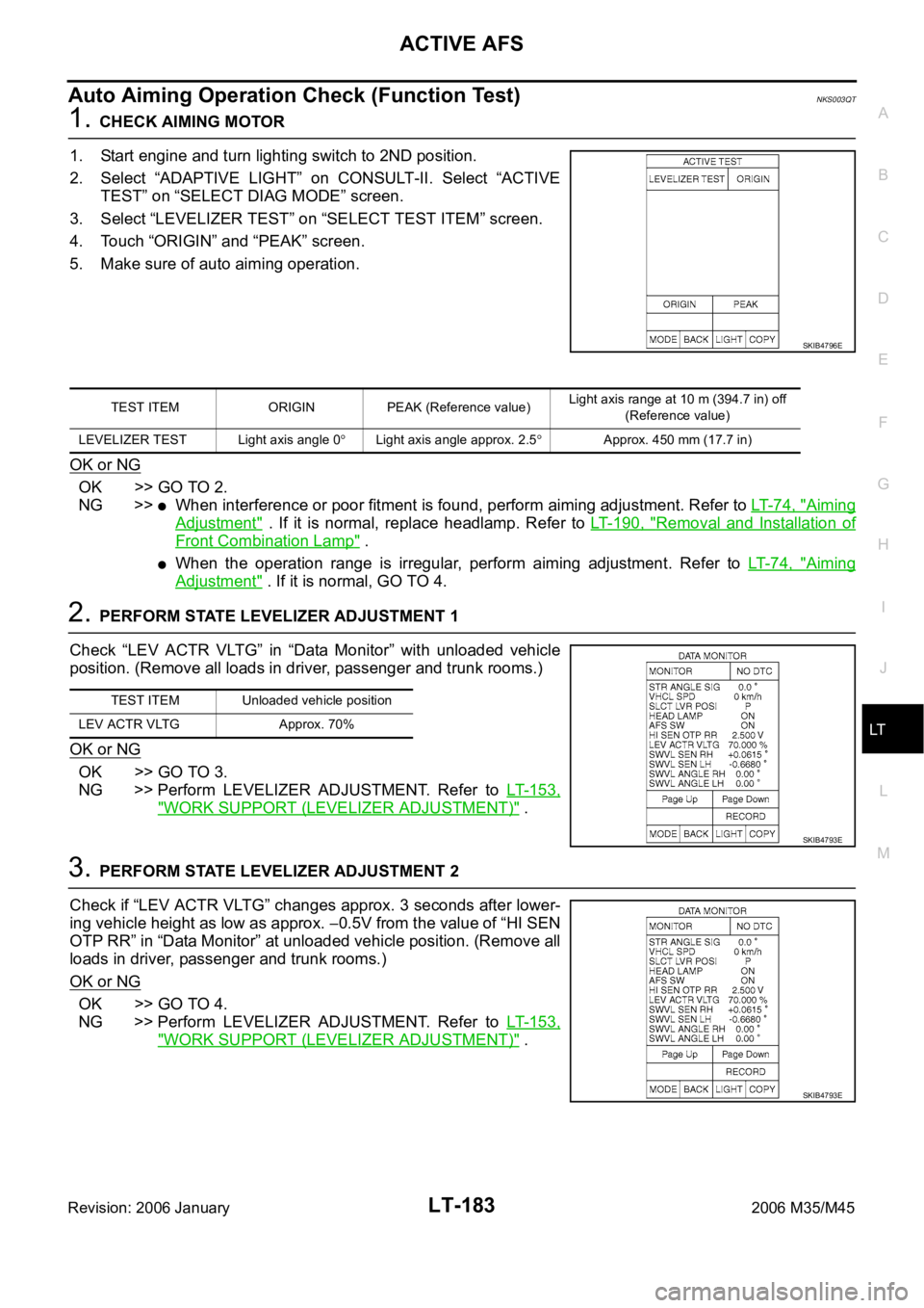
3. Select “LEVELIZER TEST” on “SELECT TEST ITEM” screen.
4. Touch “ORIGIN” and “PEAK” screen.
5. Make sure of auto aiming operation.
OK or NG
OK >> GO TO 2.
NG >>
When interference or poor fitment is found, perform aiming adjustment. Refer to LT- 7 4 , "Aiming
Adjustment" . If it is normal, replace headlamp. Refer to LT- 1 9 0 , "Removal and Installation of
Front Combination Lamp" .
When the operation range is irregular, perform aiming adjustment. Refer to LT- 7 4 , "Aiming
Adjustment" . If it is normal, GO TO 4.
2. PERFORM STATE LEVELIZER ADJUSTMENT 1
Check “LEV ACTR VLTG” in “Data Monitor” with unloaded vehicle
position. (Remove all loads in driver, passenger and trunk rooms.)
OK or NG
OK >> GO TO 3.
NG >> Perform LEVELIZER ADJUSTMENT. Refer to LT- 1 5 3 ,
"WORK SUPPORT (LEVELIZER ADJUSTMENT)" .
3. PERFORM STATE LEVELIZER ADJUSTMENT 2
Check if “LEV ACTR VLTG” changes approx. 3 seconds after lower-
ing vehicle height as low as approx.
0.5V from the value of “HI SEN
OTP RR” in “Data Monitor” at unloaded vehicle position. (Remove all
loads in driver, passenger and trunk rooms.)
OK or NG
OK >> GO TO 4.
NG >> Perform LEVELIZER ADJUSTMENT. Refer to LT- 1 5 3 ,
"WORK SUPPORT (LEVELIZER ADJUSTMENT)" .
SKIB4796E
TEST ITEM ORIGIN PEAK (Reference value)Light axis range at 10 m (394.7 in) off
(Reference value)
LEVELIZER TEST Light axis angle 0
Light axis angle approx. 2.5Approx. 450 mm (17.7 in)
TEST ITEM Unloaded vehicle position
LEV ACTR VLTG Approx. 70%
SKIB4793E
SKIB4793E
Page 4614 of 5621

ACTIVE AFS
LT-187
C
D
E
F
G
H
I
J
L
MA
B
LT
Revision: 2006 January2006 M35/M45
Auto Aiming Does Not Operate (Check Aiming Motor System Circuit)NKS003QV
1. CHECK AIMING MOTOR
1. Start engine and turn lighting switch to 2ND position.
2. Select “ADAPTIVE LIGHT” on CONSULT-II. Select “ACTIVE
TEST” on “SELECT DIAG MODE” screen.
3. Select “LEVELIZER TEST” on “SELECT TEST ITEM” screen.
4. Touch “ORIGIN” or “PEAK” screen.
5. Make sure of aiming motor operation.
OK or NG
OK >> Replace AFS control unit. Refer to LT- 1 9 1 , "Removal
and Installation of AFS Control Unit" .
NG >> GO TO 2.
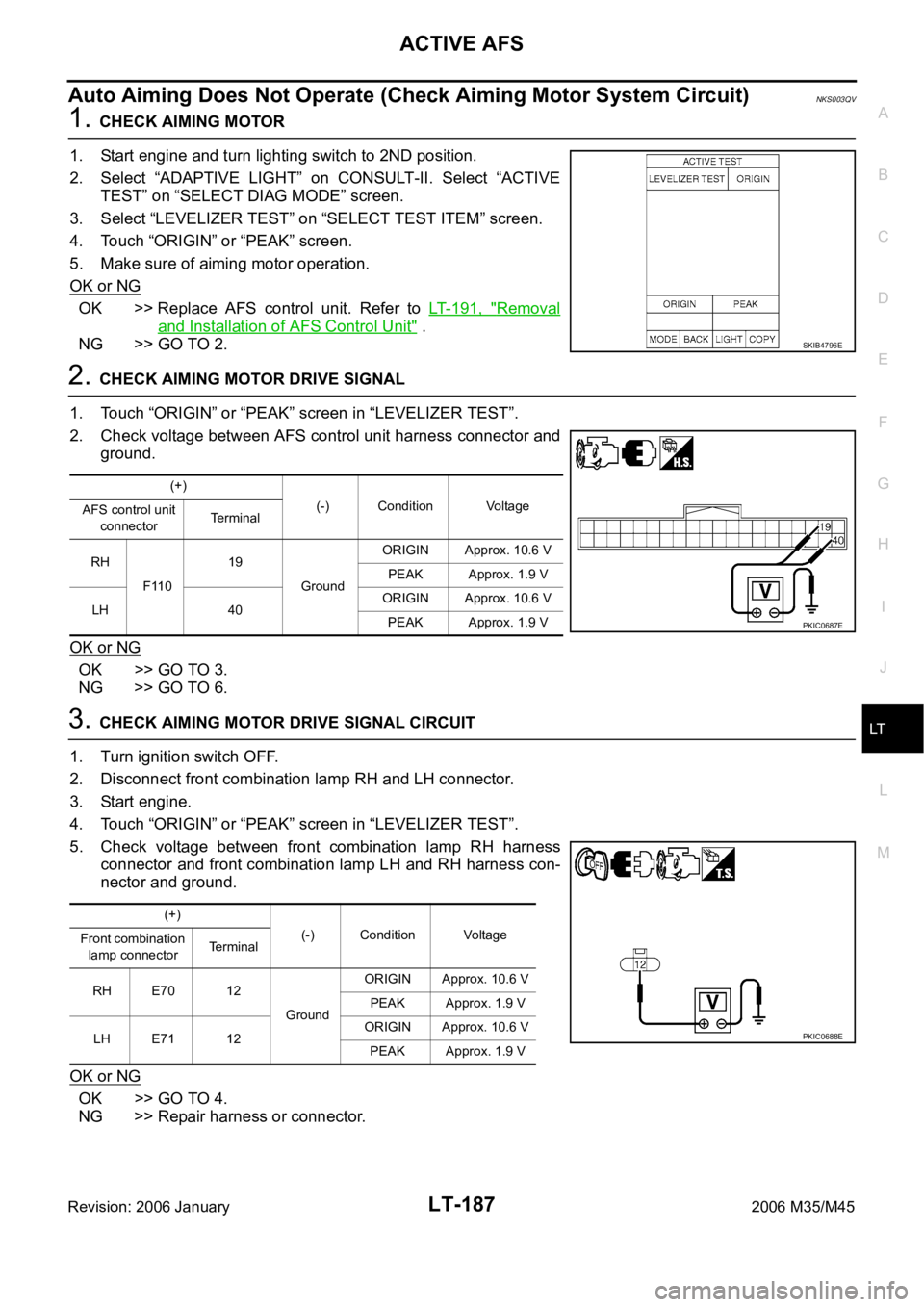
2. CHECK AIMING MOTOR DRIVE SIGNAL
1. Touch “ORIGIN” or “PEAK” screen in “LEVELIZER TEST”.
2. Check voltage between AFS control unit harness connector and
ground.
OK or NG
OK >> GO TO 3.
NG >> GO TO 6.
3. CHECK AIMING MOTOR DRIVE SIGNAL CIRCUIT
1. Turn ignition switch OFF.
2. Disconnect front combination lamp RH and LH connector.
3. Start engine.
4. Touch “ORIGIN” or “PEAK” screen in “LEVELIZER TEST”.
5. Check voltage between front combination lamp RH harness
connector and front combination lamp LH and RH harness con-
nector and ground.
OK or NG
OK >> GO TO 4.
NG >> Repair harness or connector.
SKIB4796E
(+)
(-) Condition Voltage
AFS control unit
connectorTerminal
RH
F11019
GroundORIGIN Approx. 10.6 V
PEAK Approx. 1.9 V
LH 40ORIGIN Approx. 10.6 V
PEAK Approx. 1.9 V
PKIC0687E
(+)
(-) Condition Voltage
Front combination
lamp connectorTerminal
RH E70 12
GroundORIGIN Approx. 10.6 V
PEAK Approx. 1.9 V
LH E71 12ORIGIN Approx. 10.6 V
PEAK Approx. 1.9 V
PKIC0688E
Page 4963 of 5621

PS-10
STEERING WHEEL
Revision: 2006 January2006 M35/M45
STEERING WHEELPFP:48430
On-Vehicle Inspection and ServiceNGS000D8
CHECKING CONDITION OF INSTALLATION
Check installation conditions of steering gear assembly, front suspension assembly, axle and steering col-
umn assembly.
Check if movement exists when steering wheel is moved up and down, to the left and right and to the axial
direction.
Check steering gear assembly mounting bolts and nut for looseness. Refer to PS-18, "COMPONENTS" .
CHECKING STEERING WHEEL PLAY
Turn steering wheel so that front wheels come to the straight-ahead position. Start engine and lightly turn
steering wheel to the left and right until front wheels start to move. Measure steering wheel movement on
the outer circumference.
When the measurement value is outside the standard value, check backlash for each joint of steering col-
umn assembly and installation condition of steering gear assembly.
CHECKING NEUTRAL POSITION STEERING WHEEL
Make sure that steering gear assembly, steering column assembly and steering wheel are installed in the
correct position.
Perform neutral position inspection after wheel alignment. Refer to FSU-6, "Wheel Alignment Inspection"
(2WD), FSU-23, "Wheel Alignment Inspection" (AWD).
Set vehicle to the straight-ahead position and confirm steering wheel is in the neutral position.
Loosen outer socket lock nut and turn inner socket to left and right equally to make fine adjustments if
steering wheel is not in the neutral position.
CHECKING STEERING WHEEL TURNING FORCE
1. Park vehicle on a level and dry surface, set parking brake.
2. Start engine.
3. Bring power steering fluid up to adequate operating temperature. [Make sure temperature of fluid is
approximately 50 to 80
C (122 to 176F).]
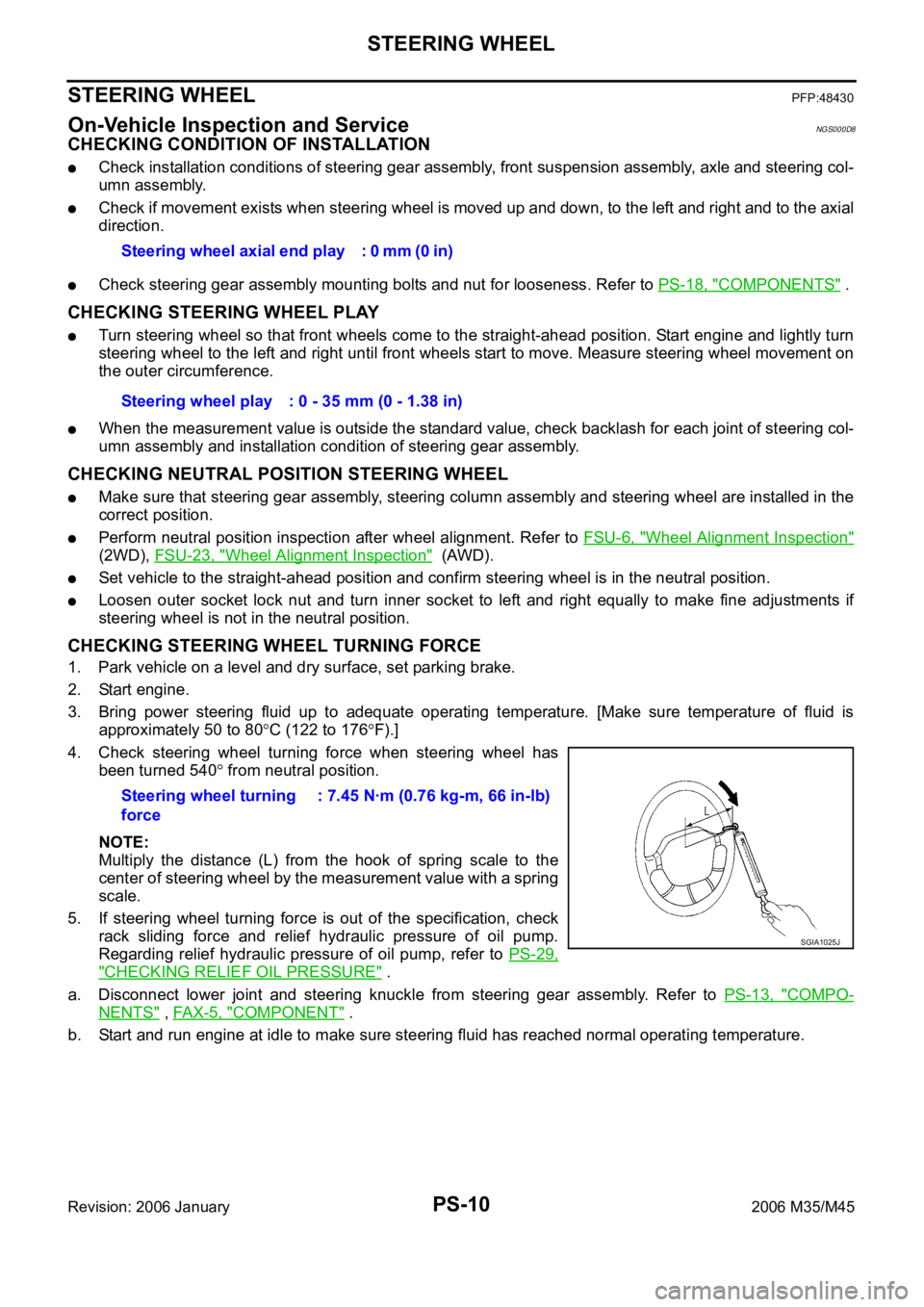
4. Check steering wheel turning force when steering wheel has
been turned 540
from neutral position.
NOTE:
Multiply the distance (L) from the hook of spring scale to the
center of steering wheel by the measurement value with a spring
scale.
5. If steering wheel turning force is out of the specification, check
rack sliding force and relief hydraulic pressure of oil pump.
Regarding relief hydraulic pressure of oil pump, refer to PS-29,
"CHECKING RELIEF OIL PRESSURE" .
a. Disconnect lower joint and steering knuckle from steering gear assembly. Refer to PS-13, "
COMPO-
NENTS" , FAX-5, "COMPONENT" .
b. Start and run engine at idle to make sure steering fluid has reached normal operating temperature. Steering wheel axial end play : 0 mm (0 in)
Steering wheel play : 0 - 35 mm (0 - 1.38 in)
Steering wheel turning
force: 7.45 Nꞏm (0.76 kg-m, 66 in-lb)
SGIA1025J
Page 5425 of 5621
![INFINITI M35 2006 Factory Repair Manual STC-10
[EPS]
TROUBLE DIAGNOSIS
Revision: 2006 January2006 M35/M45
3. CHECK POWER STEERING CONTROL UNIT POWER SUPPLY CIRCUIT
Turn ignition switch ON, and then check voltage between power
steer INFINITI M35 2006 Factory Repair Manual STC-10
[EPS]
TROUBLE DIAGNOSIS
Revision: 2006 January2006 M35/M45
3. CHECK POWER STEERING CONTROL UNIT POWER SUPPLY CIRCUIT
Turn ignition switch ON, and then check voltage between power
steer](/img/42/57023/w960_57023-5424.png)
STC-10
[EPS]
TROUBLE DIAGNOSIS
Revision: 2006 January2006 M35/M45
3. CHECK POWER STEERING CONTROL UNIT POWER SUPPLY CIRCUIT
Turn ignition switch ON, and then check voltage between power
steering control unit harness connector M8 and ground.
OK or NG
OK >> Power supply and ground circuit are normal.
NG >> Power supply circuit open or shorted. Repair or replace
any inoperative parts.
Symptom: The Steering Force Does Not Change Smoothly According to the
Vehicle Speed
NGS000E4
Heavy steering force with the static steering/light steering force during high-speed driving
1. POWER STEERING SOLENOID VALVE SIGNAL INSPECTION 1
1. Start engine.
2. Change the vehicle speed from 0 to 100 km/h (0 to 62 MPH)
slowly, and then check voltage between power steering control
unit harness connector M8 and ground.
OK or NG
OK >> GO TO 2.
NG >> GO TO 7.
2. POWER STEERING SOLENOID VALVE SIGNAL INSPECTION 2
1. Activate fail-safe function by running the engine speed at 1,500 rpm or higher for 10 seconds with the
vehicle stopped.
2. Change the engine speed to the idling, to approximately 1,600
rpm, and to approximately 3,000 rpm slowly, and then check
voltage between power steering control unit harness connector
M8 and ground.
OK or NG
OK >> GO TO 3.
NG >> GO TO 8.
3. CHECK POWER STEERING SOLENOID VALVE CONNECTOR
Turn ignition switch OFF, disconnect power steering solenoid valve harness connector, and check terminal for
deformation, disconnection, looseness, etc.
OK or NG
OK >> GO TO 4.
NG >> Harness or connector open or shorted. Repair or replace any inoperative parts. Terminal 1 – ground : Battery voltage (Approx. 12 V)
SGIA1232E
Terminal 7 – ground : The voltage has changed from
approximately 4.4 - 6.6 V to
approximately 2.4 - 3.6 V
SGIA1233E
Terminal 7 – ground : The voltage has changed from
approximately 5.5 V to approxi-
mately 2.1 V step-by-step.
SGIA1233E
Page 5461 of 5621
![INFINITI M35 2006 Factory Repair Manual STC-46
[RAS]
TROUBLE DIAGNOSIS
Revision: 2006 January2006 M35/M45
Diagnosis Chart by Symptom 1NGS000F1
1. CHECK SELF-DIAGNOSTIC RESULTS
Perform RAS self-diagnosis.
With CONSULT-II: STC-28, "SELF-D INFINITI M35 2006 Factory Repair Manual STC-46
[RAS]
TROUBLE DIAGNOSIS
Revision: 2006 January2006 M35/M45
Diagnosis Chart by Symptom 1NGS000F1
1. CHECK SELF-DIAGNOSTIC RESULTS
Perform RAS self-diagnosis.
With CONSULT-II: STC-28, "SELF-D](/img/42/57023/w960_57023-5460.png)
STC-46
[RAS]
TROUBLE DIAGNOSIS
Revision: 2006 January2006 M35/M45
Diagnosis Chart by Symptom 1NGS000F1
1. CHECK SELF-DIAGNOSTIC RESULTS
Perform RAS self-diagnosis.
With CONSULT-II: STC-28, "SELF-DIAG RESULT MODE"
Without CONSULT-II: STC-31, "Diagnosis Procedure with Self-Diagnosis Function (Without CONSULT-
II)"
Are malfunctioning items displayed in self-diagnosis results?
YES >> Repair or replace any malfunctioning items.
NO >> GO TO 2.
2. CHECK RAS STATIC/DYNAMIC CHARACTERISTICS
Check RAS static/dynamic characteristics. Refer to STC-48, "
Check RAS Static/Dynamic Characteristics" .
Is the malfunction corrected?
YES >> INSPECTION END
NO >> Perform the following check, and then check the symptom again.
Adjust neutral position of steering angle sensor. Refer to BRC-6, "Adjustment of Steering Angle
Sensor Neutral Position" .
Steering angle sensor mounting condition. Refer to BRC-63, "Removal and Installation" .
Diagnosis Chart by Symptom 2NGS000F2
The steering force does not change smoothly according to the vehicle speed (Heavy steering force with the
vehicle stopped/Light handle operation during high-speed driving)
1. CHECK (1): POWER STEERING SOLENOID VALVE SIGNAL
1. Start engine.
2. Change the vehicle speed from 0 to 100 km/h (0 to 62 MPH)
slowly, and then check voltage RAS control unit harness con-
nector B127.
OK or NG
OK >> GO TO 2.
NG >> GO TO 7.
2. CHECK (2): POWER STEERING SOLENOID VALVE SIGNAL
1. Activate fail-safe function by running engine speed at 1,500 rpm or higher for 10 seconds with the vehicle
stopped.
2. Change the engine speed to the idling speed, approx. 1,600
rpm, and approximately 3,000 rpm slowly, and then check volt-
age RAS control unit harness connector B127.
OK or NG
OK >> GO TO 3.
NG >> GO TO 7.Terminal 36 – 34 : The voltage has changed from
approximately 4.4 - 6.6 V to approxi-
mately 2.4 - 3.6 V.
SGIA1281E
Terminal 36 – 34 : The voltage is changed from
approximately 5.5 V to approximately
2.1 V step-by-step.
SGIA1281E
Page 5485 of 5621

TF-20
TROUBLE DIAGNOSIS
Revision: 2006 January2006 M35/M45
Trouble Diagnosis Chart for SymptomsNDS000DK
If AWD warning lamp turns ON, perform self-diagnosis. Refer to TF-22, "SELF-DIAG RESULT MODE" .
NOTE:
Light tight-corner braking symptom may occur depending on driving conditions. This is not malfunction.
AWD Control Unit Input/Output Signal Reference ValuesNDS000DL
AWD CONTROL UNIT INSPECTION TABLE
Specifications with CONSULT-II
Symptom Condition Check item Reference page
AWD warning lamp does not turn ON when
the ignition switch is turned to ON.
(AWD warning lamp check)Ignition switch: ONCAN communication line
TF-33
Unified meter and A/C amp.
Unified meter control unit
AWD warning lamp does not turn OFF sev-
eral seconds after engine started.Engine runningCAN communication line
TF-33
Power supply and ground for AWD con-
trol unit
Unified meter and A/C amp.
Unified meter control unit
AWD solenoid
AWD actuator relay (integrated in AWD
control unit)
Wheel sensor
Heavy tight-corner braking symptom occurs
when the vehicle is driven and the steering
wheel is turned fully to either side after the
engine is started. (See NOTE.)
While driving
Steering wheel is
turned fully to either
sidesCAN communication line
TF-35Accelerator pedal position signal
AWD solenoid
Mechanical malfunction of electric con-
trolled coupling (clutch sticking etc.)
Vehicle does not enter AWD mode even
though AWD warning lamp turned to OFF.While drivingCAN communication line
TF-36
AWD solenoid
Mechanical malfunction of electric con-
trolled coupling (Mechanical engage-
ment of clutch is not possible.)
While driving, AWD warning lamp flashes
rapidly. (When flashing in approx. 1 minute
and then turning OFF.)
Rapid flashing: 2 times/secondWhile drivingProtection function is activated due to
heavy load to electric controlled cou-
pling. (AWD system is not malfunction-
ing. Also, optional distribution of torque
sometimes becomes rigid before lamp
flashes rapidly, but it is not malfunction.)TF-37
While driving, AWD warning lamp flashes
slowly. (When continuing to flash until turn-
ing ignition switch OFF)
Slow flashing: 1 time/2 secondsWhile driving
Vehicle speed: 20 km/h
(12 MPH) or moreTire size is different between front and
rear of vehicle.TF-37
Monitor item [Unit] Content Condition Display value
FR RH SENSOR [km/h] or [mph]Wheel speed (Front wheel
right)Vehicle stopped 0.00 km/h (0.00 mph)
Vehicle running
CAUTION:
Check air pressure of tire under
standard condition.Approximately equal to
the indication on speed-
ometer (Inside of
10%)
FR LH SENSOR [km/h] or [mph]Wheel speed (Front wheel
left)Vehicle stopped 0.00 km/h (0.00 mph)
Vehicle running
CAUTION:
Check air pressure of tire under
standard condition.Approximately equal to
the indication on speed-
ometer (Inside of
10%)
Page 5500 of 5621

TROUBLE DIAGNOSIS FOR SYMPTOMS
TF-35
C
E
F
G
H
I
J
K
L
MA
B
TF
Revision: 2006 January2006 M35/M45
4. CHECK AWD CONTROL UNIT
Check AWD control unit input/output signal. Refer to TF-20, "
AWD Control Unit Input/Output Signal Reference
Va l u e s" .
OK or NG
OK >> GO TO 5.
NG >> Check AWD control unit pin terminals for damage or loose connection with harness connector. If
any items are damaged, repair or replace damaged parts.
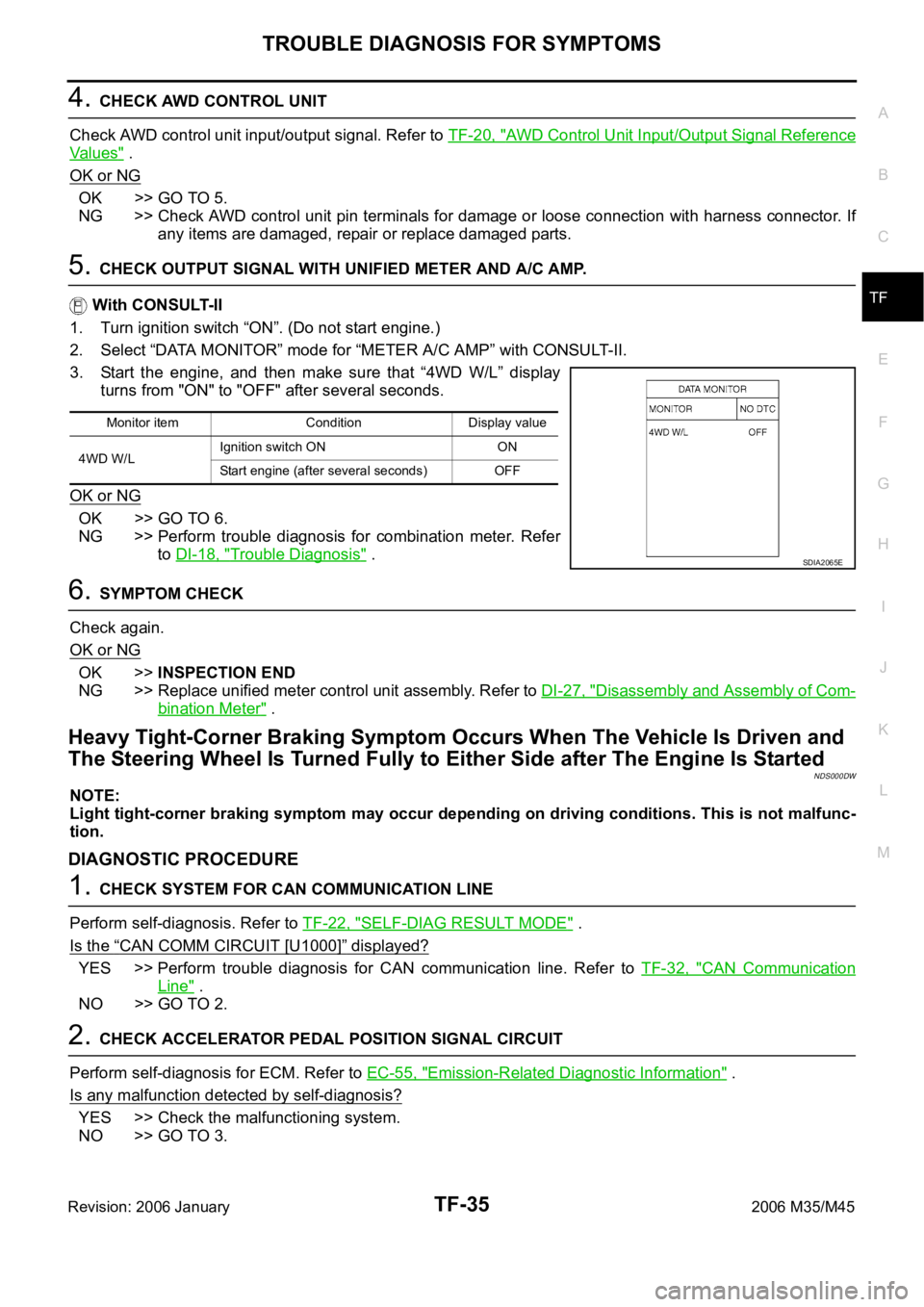
5. CHECK OUTPUT SIGNAL WITH UNIFIED METER AND A/C AMP.
With CONSULT-II
1. Turn ignition switch “ON”. (Do not start engine.)
2. Select “DATA MONITOR” mode for “METER A/C AMP” with CONSULT-II.
3. Start the engine, and then make sure that “4WD W/L” display
turns from "ON" to "OFF" after several seconds.
OK or NG
OK >> GO TO 6.
NG >> Perform trouble diagnosis for combination meter. Refer
to DI-18, "
Trouble Diagnosis" .
6. SYMPTOM CHECK
Check again.
OK or NG
OK >>INSPECTION END
NG >> Replace unified meter control unit assembly. Refer to DI-27, "
Disassembly and Assembly of Com-
bination Meter" .
Heavy Tight-Corner Braking Symptom Occurs When The Vehicle Is Driven and
The Steering Wheel Is Turned Fully to Either Side after The Engine Is Started
NDS000DW
NOTE:
Light tight-corner braking symptom may occur depending on driving conditions. This is not malfunc-
tion.
DIAGNOSTIC PROCEDURE
1. CHECK SYSTEM FOR CAN COMMUNICATION LINE
Perform self-diagnosis. Refer to TF-22, "
SELF-DIAG RESULT MODE" .
Is the
“CAN COMM CIRCUIT [U1000]” displayed?
YES >> Perform trouble diagnosis for CAN communication line. Refer to TF-32, "CAN Communication
Line" .
NO >> GO TO 2.
2. CHECK ACCELERATOR PEDAL POSITION SIGNAL CIRCUIT
Perform self-diagnosis for ECM. Refer to EC-55, "
Emission-Related Diagnostic Information" .
Is any malfunction detected by self-diagnosis?
YES >> Check the malfunctioning system.
NO >> GO TO 3.
Monitor item Condition Display value
4WD W/LIgnition switch ON ON
Start engine (after several seconds) OFF
SDIA2065E