heater INFINITI M35 2006 Factory Service Manual
[x] Cancel search | Manufacturer: INFINITI, Model Year: 2006, Model line: M35, Model: INFINITI M35 2006Pages: 5621, PDF Size: 65.56 MB
Page 450 of 5621

ATC-3
C
D
E
F
G
H
I
K
L
MA
B
AT C
Revision: 2006 January2006 M35/M45 INSPECTION FLOW ......................................... . 111
Memory Function .................................................. 112
INSPECTION FLOW .......................................... 112
Ambient Sensor Circuit ......................................... 113
COMPONENT DESCRIPTION .......................... 113
AMBIENT TEMPERATURE INPUT PROCESS .. 113
DIAGNOSIS PROCEDURE FOR AMBIENT
SENSOR ............................................................ 113
COMPONENT INSPECTION ............................. 115
In-Vehicle Sensor Circuit ....................................... 116
COMPONENT DESCRIPTION .......................... 116
DIAGNOSIS PROCEDURE FOR IN-VEHICLE
SENSOR ............................................................ 117
COMPONENT INSPECTION ............................. 118
Sunload Sensor Circuit ......................................... 119
COMPONENT DESCRIPTION .......................... 119
SUNLOAD INPUT PROCESS ........................... 119
DIAGNOSIS PROCEDURE FOR SUNLOAD
SENSOR ............................................................ 119
COMPONENT INSPECTION ............................121
Intake Sensor Circuit ............................................122
COMPONENT DESCRIPTION .........................122
DIAGNOSIS PROCEDURE FOR INTAKE SEN-
SOR ..................................................................122
COMPONENT INSPECTION ............................123
CONTROLLER .......................................................124
Removal and Installation of Multifunction Switch . 124
REMOVAL ........................................................
.124
INSTALLATION .................................................124
AUTO AMP .............................................................125
Removal and Installation of Unified Meter and A/C
Auto Amp. ............................................................125
REMOVAL ........................................................
.125
INSTALLATION .................................................125
AMBIENT SENSOR ................................................126
Removal and Installation ......................................126
REMOVAL ........................................................
.126
INSTALLATION .................................................126
IN-VEHICLE SENSOR ............................................127
Removal and Installation ......................................127
REMOVAL ........................................................
.127
INSTALLATION .................................................127
SUNLOAD SENSOR ..............................................128
Removal and Installation ......................................128
REMOVAL ........................................................
.128
INSTALLATION .................................................128
INTAKE SENSOR .................................................. .129
Removal and Installation ......................................129
REMOVAL ........................................................
.129
INSTALLATION .................................................129
BLOWER UNIT .......................................................130
Removal and Installation ......................................130
REMOVAL ........................................................
.130
INSTALLATION .................................................130
Disassembly and Assembly .................................131
BLOWER MOTOR ..................................................132
Removal and Installation ......................................132
REMOVAL ........................................................
.132
INSTALLATION .................................................132INTAKE DOOR MOTOR .........................................133
Removal and Installation ......................................133
REMOVAL ........................................................
.133
INSTALLATION .................................................133
IN-CABIN MICROFILTER .......................................134
Removal and Installation ......................................134
FUNCTION .......................................................
.134
REPLACEMENT TIMING ..................................134
REPLACEMENT PROCEDURES .....................134
HEATER & COOLING UNIT ASSEMBLY ...............135
Removal and Installation ......................................135
REMOVAL ........................................................
.135
INSTALLATION .................................................136
Disassembly and Assembly ..................................138
MODE DOOR MOTOR ............................................140
Removal and Installation ......................................140
REMOVAL ........................................................
.140
INSTALLATION .................................................140
AIR MIX DOOR MOTOR .........................................141
Removal and Installation ......................................141
REMOVAL ........................................................
.141
INSTALLATION .................................................141
UPPER VENTILATOR DOOR MOTOR ..................142
Removal and Installation ......................................142
REMOVAL ........................................................
.142
INSTALLATION .................................................142
HEATER CORE .......................................................143
Removal and Installation ......................................143
REMOVAL ........................................................
.143
INSTALLATION .................................................143
DUCTS AND GRILLES ...........................................144
Removal and Installation ......................................144
COMPONENT LAYOUT ....................................144
REMOVAL ........................................................
.146
INSTALLATION .................................................150
REFRIGERANT LINES ...........................................151
HFC-134a (R-134a) Service Procedure ...............151
SETTING OF SERVICE TOOLS AND EQUIP-
MENT ................................................................151
Components ....................................................
.....153
VQ35DE ............................................................153
VK45DE .............................................................154
Removal and Installation of Compressor ..............155
REMOVAL ........................................................
.155
INSTALLATION .................................................157
Check Disc to Pulley Clearance ...........................157
Removal and Installation of Low-Pressure Flexible
Hose and Pipe ......................................................158
REMOVAL ........................................................
.158
INSTALLATION .................................................158
Removal and Installation of High-Pressure Flexible
Hose .....................................................................159
REMOVAL ........................................................
.159
INSTALLATION .................................................160
Removal and Installation of High-Pressure Pipe 1
(Engine Compartment) .........................................160
REMOVAL ........................................................
.160
INSTALLATION .................................................161
Removal and Installation of Low-Pressure Pipe 1
Page 526 of 5621

TROUBLE DIAGNOSIS
ATC-79
C
D
E
F
G
H
I
K
L
MA
B
AT C
Revision: 2006 January2006 M35/M45
Mode Door Control Specification
COMPONENT DESCRIPTION
Mode Door Motor
The mode door motors are attached to the heater & cooling unit
assembly. It rotates so that air is discharged from the outlet set by
the unified meter and A/C amp. Motor rotation is conveyed to a link
which activates the mode door.
DIAGNOSIS PROCEDURE FOR MODE DOOR MOTOR
SYMPTOM: Mode door motor does not operate normally.
Perform diagnosis procedure. Refer to AT C - 7 0 , "
DIAGNOSIS PROCEDURE FOR LAN CIRCUIT" .
RJIA1778E
RJIA4057E
RJIA4058E
Page 529 of 5621

ATC-82
TROUBLE DIAGNOSIS
Revision: 2006 January2006 M35/M45
Upper Ventilator Door Control Specification
COMPONENT DESCRIPTION
Upper Ventilator Door Motor
The upper ventilator door motor is attached to the heater & cooling
unit assembly. It rotates so that air is discharged from the outlet set
by the unified meter and A/C amp. Motor rotation is conveyed to a
rod which activates the upper ventilator door.
DIAGNOSIS PROCEDURE FOR UPPER VENTILATOR DOOR MOTOR
SYMPTOM: Upper ventilator door motor does not operate normally.
Perform diagnosis procedure. Refer to AT C - 7 0 , "
DIAGNOSIS PROCEDURE FOR LAN CIRCUIT" .
RJIA4061E
RJIA4062E
Page 532 of 5621

TROUBLE DIAGNOSIS
ATC-85
C
D
E
F
G
H
I
K
L
MA
B
AT C
Revision: 2006 January2006 M35/M45
COMPONENT DESCRIPTION
Air Mix Door Motor
The air mix door motors are attached to the heater & cooling unit
assembly. It rotates so that the air mix door is opened or closed to a
position set by the unified meter and A/C amp. Motor rotation is then
conveyed through a shaft and the air mix door position feedback is
then sent to the unified meter and A/C amp. by PBR built-in air mix
door motor.
DIAGNOSIS PROCEDURE FOR AIR MIX DOOR MOTOR
SYMPTOM: Discharge air temperature does not change.
Perform diagnosis procedure. Refer to AT C - 7 0 , "
DIAGNOSIS PROCEDURE FOR LAN CIRCUIT" .
Air Mix Door Motor PBR CircuitNJS000GR
SYMPTOM:
Discharge air temperature does not change.
PBR circuit is open or shorted.
DIAGNOSIS PROCEDURE FOR AIR MIX DOOR MOTOR PBR
Perform diagnosis procedure. Refer to AT C - 7 0 , "DIAGNOSIS PROCEDURE FOR LAN CIRCUIT" .
RJIA4064E
RJIA4065E
Page 544 of 5621

TROUBLE DIAGNOSIS
ATC-97
C
D
E
F
G
H
I
K
L
MA
B
AT C
Revision: 2006 January2006 M35/M45
5. CHECK BCM INPUT (COMPRESSOR ON) SIGNAL
Check compressor ON/OFF signal. Refer to AT C - 4 0 , "
CONSULT-II
Function (ECM)" .
OK or NG
OK >> GO TO 8.
NG >> GO TO 6.
6. CHECK REFRIGERANT PRESSURE SENSOR
WITH CONSULT-II
1. Start the engine.
2. Check voltage of refrigerant pressure sensor. Refer to EC-149, "
CONSULT-II Reference Value in Data
Monitor" (VQ35DE) or EC-862, "CONSULT-II Reference Value in Data Monitor" (VK45DE).
WITHOUT CONSULT-II
1. Start the engine.
2. Check voltage between ECM harness connector F108 terminal
70 and ground.
OK or NG
OK >>WITH CONSULT-II: GO TO 7.
WITHOUT CONSULT-II: Repair harness or connector.
NG >> Refer to EC-692, "
REFRIGERANT PRESSURE SENSOR" (VQ35DE) or EC-1434, "REFRIGER-
ANT PRESSURE SENSOR" (VK45DE).
7. CHECK ECM INPUT (FAN ON) SIGNAL
Check FAN ON/OFF signal. Refer to AT C - 4 0 , "
CONSULT-II Function
(ECM)" .
OK or NG
OK >> GO TO 8.
NG >> Repair harness or connector.A/C SW ON : AIR COND SIG ON
A/C SW OFF : AIR COND SIG OFF
RJIA3646E
Terminals
Condition Voltage (+)
(
)
ECM
connectorTerminal
No.
F108 70 GroundA/C switch: ON
(Blower motor operates.)Approx. 1.0 -
4.0 V
PBIB1188E
FAN SW ON : HEATER FAN SW ON
FAN SW OFF : HEATER FAN SW OFF
RJIA3646E
Page 563 of 5621

ATC-116
TROUBLE DIAGNOSIS
Revision: 2006 January2006 M35/M45
In-Vehicle Sensor CircuitNJS000H1
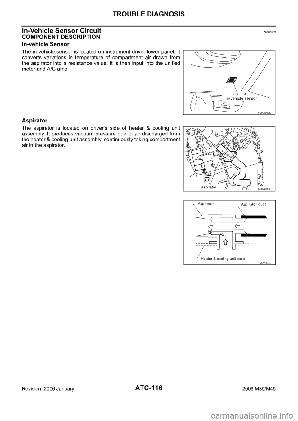
COMPONENT DESCRIPTION
In-vehicle Sensor
The in-vehicle sensor is located on instrument driver lower panel. It
converts variations in temperature of compartment air drawn from
the aspirator into a resistance value. It is then input into the unified
meter and A/C amp.
Aspirator
The aspirator is located on driver’s side of heater & cooling unit
assembly. It produces vacuum pressure due to air discharged from
the heater & cooling unit assembly, continuously taking compartment
air in the aspirator.
RJIA4092E
RJIA4093E
RJIA1804E
Page 569 of 5621

ATC-122
TROUBLE DIAGNOSIS
Revision: 2006 January2006 M35/M45
Intake Sensor CircuitNJS000H3
COMPONENT DESCRIPTION
Intake Sensor
The intake sensor is located on the heater & cooling unit assembly. It
converts temperature of air after it passes through the evaporator
into a resistance value which is then input to the unified meter and A/
C amp.
DIAGNOSIS PROCEDURE FOR INTAKE SENSOR
SYMPTOM: Intake sensor circuit is open or shorted. (24 or 24 is
indicated on unified meter and A/C amp. as a result of performing
self-diagnosis STEP-2.)
1. CHECK VOLTAGE BETWEEN INTAKE SENSOR AND GROUND
1. Disconnect intake sensor connector.
2. Turn ignition switch ON.
3. Check voltage between intake sensor harness connector M82
terminal 1 and ground.
OK or NG
OK >> GO TO 2.
NG >> GO TO 4.
2. CHECK CIRCUIT CONTINUITY BETWEEN INTAKE SENSOR AND UNIFIED METER AND A/C AMP.
1. Turn ignition switch OFF.
2. Disconnect unified meter and A/C amp. connector.
3. Check continuity between intake sensor harness connector M82
terminal 2 and unified meter and A/C amp. harness connector
M65 terminal 59.
OK or NG
OK >> GO TO 3.
NG >> Repair harness or connector.
RJIA4103E
RJIA4104E
1 – Ground : Approx. 5 V
RJIA4215E
2 – 59 : Continuity should exist.
RJIA4106E
Page 582 of 5621

HEATER & COOLING UNIT ASSEMBLY
ATC-135
C
D
E
F
G
H
I
K
L
MA
B
AT C
Revision: 2006 January2006 M35/M45
HEATER & COOLING UNIT ASSEMBLYPFP:27110
Removal and InstallationNJS000HF
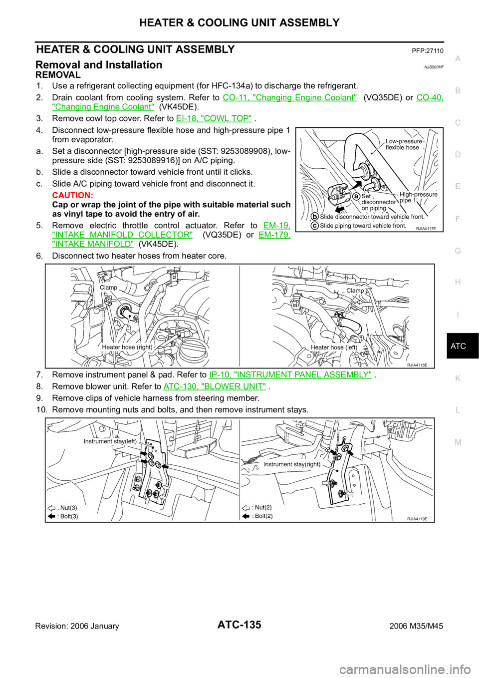
REMOVAL
1. Use a refrigerant collecting equipment (for HFC-134a) to discharge the refrigerant.
2. Drain coolant from cooling system. Refer to CO-11, "
Changing Engine Coolant" (VQ35DE) or CO-40,
"Changing Engine Coolant" (VK45DE).
3. Remove cowl top cover. Refer to EI-18, "
COWL TOP" .
4. Disconnect low-pressure flexible hose and high-pressure pipe 1
from evaporator.
a. Set a disconnector [high-pressure side (SST: 9253089908), low-
pressure side (SST: 9253089916)] on A/C piping.
b. Slide a disconnector toward vehicle front until it clicks.
c. Slide A/C piping toward vehicle front and disconnect it.
CAUTION:
Cap or wrap the joint of the pipe with suitable material such
as vinyl tape to avoid the entry of air.
5. Remove electric throttle control actuator. Refer to EM-19,
"INTAKE MANIFOLD COLLECTOR" (VQ35DE) or EM-179,
"INTAKE MANIFOLD" (VK45DE).
6. Disconnect two heater hoses from heater core.
7. Remove instrument panel & pad. Refer to IP-10, "
INSTRUMENT PANEL ASSEMBLY" .
8. Remove blower unit. Refer to ATC-130, "
BLOWER UNIT" .
9. Remove clips of vehicle harness from steering member.
10. Remove mounting nuts and bolts, and then remove instrument stays.
RJIA4117E
RJIA4118E
RJIA4119E
Page 583 of 5621

ATC-136
HEATER & COOLING UNIT ASSEMBLY
Revision: 2006 January2006 M35/M45
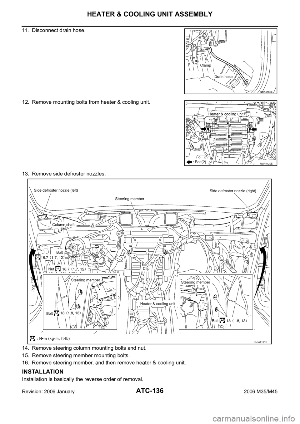
11. Disconnect drain hose.
12. Remove mounting bolts from heater & cooling unit.
13. Remove side defroster nozzles.
14. Remove steering column mounting bolts and nut.
15. Remove steering member mounting bolts.
16. Remove steering member, and then remove heater & cooling unit.
INSTALLATION
Installation is basically the reverse order of removal.
RJIA4180E
RJIA4120E
RJIA4121E
Page 584 of 5621

HEATER & COOLING UNIT ASSEMBLY
ATC-137
C
D
E
F
G
H
I
K
L
MA
B
AT C
Revision: 2006 January2006 M35/M45
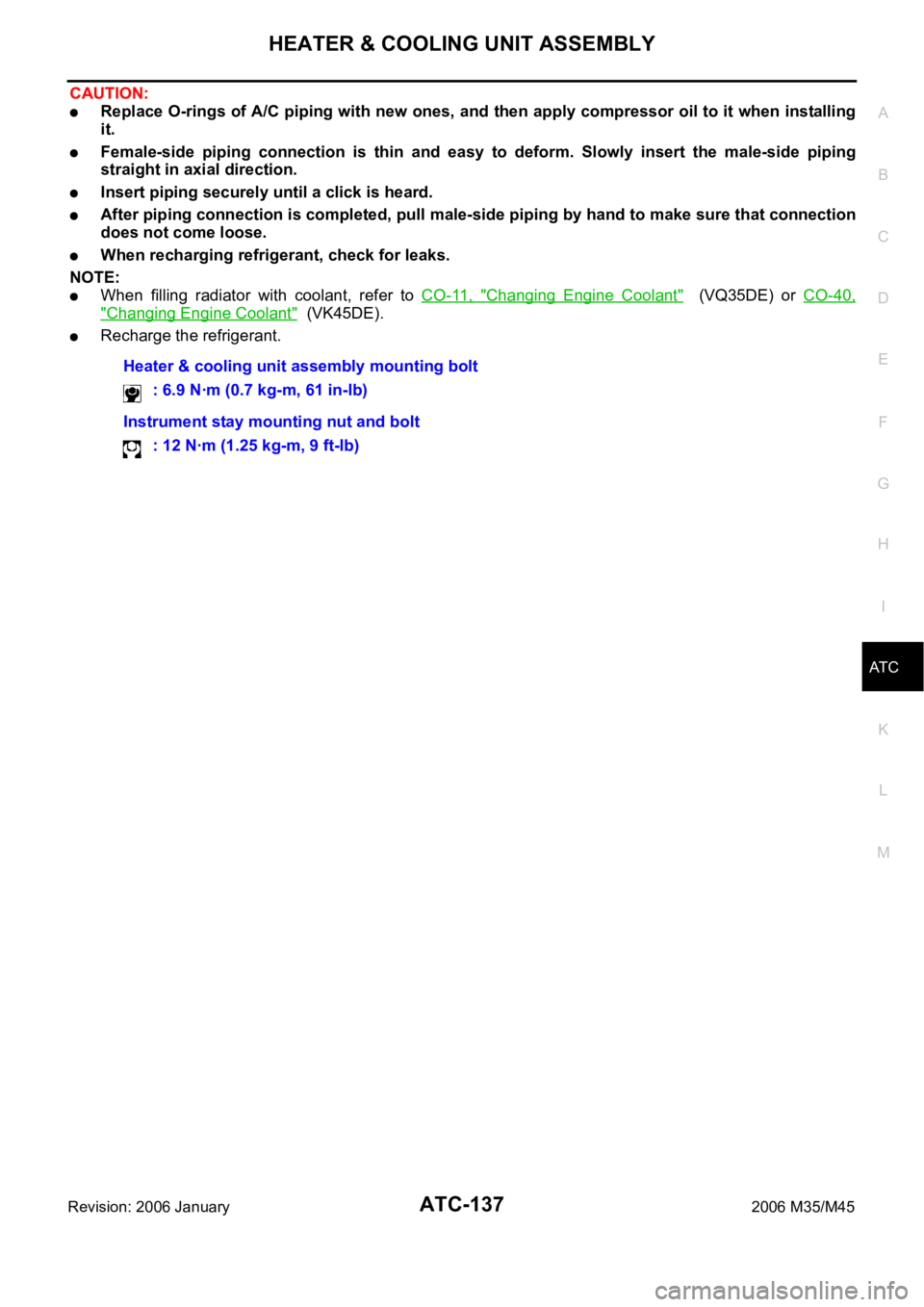
CAUTION:
Replace O-rings of A/C piping with new ones, and then apply compressor oil to it when installing
it.
Female-side piping connection is thin and easy to deform. Slowly insert the male-side piping
straight in axial direction.
Insert piping securely until a click is heard.
After piping connection is completed, pull male-side piping by hand to make sure that connection
does not come loose.
When recharging refrigerant, check for leaks.
NOTE:
When filling radiator with coolant, refer to CO-11, "Changing Engine Coolant" (VQ35DE) or CO-40,
"Changing Engine Coolant" (VK45DE).
Recharge the refrigerant.
Heater & cooling unit assembly mounting bolt
: 6.9 Nꞏm (0.7 kg-m, 61 in-lb)
Instrument stay mounting nut and bolt
: 12 Nꞏm (1.25 kg-m, 9 ft-lb)