battery INFINITI M35 2006 Factory Service Manual
[x] Cancel search | Manufacturer: INFINITI, Model Year: 2006, Model line: M35, Model: INFINITI M35 2006Pages: 5621, PDF Size: 65.56 MB
Page 4783 of 5621

MA-6
GENERAL MAINTENANCE
Revision: 2006 January2006 M35/M45
UNDER THE HOOD AND VEHICLE
The maintenance items listed here should be checked periodically (e.g. each time you check the engine oil or refuel). Parking brakeCheck that the pedal has the proper travel and make sure that the vehicle is
held securely on a fairly steep hill when only the parking brake is applied.PB-2
Automatic transmis-
sion "Park" mecha-
nismCheck that the lock release button on the selector lever operates properly and
smoothly. On a fairly steep hill check that the vehicle is held securely with the
selector lever in the P (Park) position without applying any brakes.— ItemReference page
ItemReference page
Windshield washer
fluidCheck that there is adequate fluid in the tank. —
Engine coolant levelCheck the coolant level when the engine is cold.MA-15
, MA-22
Radiator and hosesCheck the front of the radiator and clean off any dirt, insects, leaves, etc., that
may have accumulated. Make sure the hoses have no cracks, deformation,
deterioration or loose connections.—
Brake fluid levelMake sure that the brake fluid level is between the “MAX” and “MIN” lines on
the reservoir.MA-35
BatteryCheck the fluid level in each cell. It should be between the “MAX” and “MIN”
lines. Vehicles operated in high temperatures or under severe conditions
require frequent checks of the battery fluid level.SC-5, "
CHECKING
ELECTROLYTE LEVEL"
Engine drive beltsMake sure that no belt is frayed, worn, cracked or oily.MA-14, MA-22
Engine oil levelCheck the level on the oil level gauge after parking the vehicle on a level spot
and turning off the engine.MA-18, MA-25
Power steering fluid
level and linesCheck the level on the dipstick with the engine off. Check the lines for improper
attachment, leaks, cracks, etc.MA-37
Exhaust systemMake sure there are no loose supports, cracks or holes. If the sound of the
exhaust seems unusual or there is a smell of exhaust fumes, immediately
locate the trouble and correct it.MA-29
UnderbodyThe underbody is frequently exposed to corrosive substances such as those
used on icy roads or to control dust. It is very important to remove these sub-
stances, otherwise rust will form on the floor pan, frame, fuel lines and around
the exhaust system. At the end of winter, the underbody should be thoroughly
flushed with plain water, being careful to clean those areas where mud and dirt
can easily accumulate.—
Fluid leaksCheck under the vehicle for fuel, oil, water or other fluid leaks after the vehicle
has been parked for a while. Water dripping from the air conditioner after use is
normal. If you should notice any leaks or gasoline fumes are evident, check for
the cause and correct it immediately.—
Page 4828 of 5621

PG-1
POWER SUPPLY, GROUND & CIRCUIT ELEMENTS
K ELECTRICAL
CONTENTS
C
D
E
F
G
H
I
J
L
M
SECTION PG
A
B
PG
Revision: 2006 January2006 M35/M45
POWER SUPPLY, GROUND & CIRCUIT ELEMENTS
POWER SUPPLY ROUTING CIRCUIT ...................... 3
Schematic ................................................................ 3
Wiring Diagram — POWER — ................................. 5
BATTERY POWER SUPPLY — IGNITION SW.
IN ANY POSITION ................................................ 5
ACCESSORY POWER SUPPLY — IGNITION
SW. IN “ACC” OR “ON” ........................................ 11
IGNITION POWER SUPPLY — IGNITION SW.
IN “ON” AND/OR “START” .................................. 12
Fuse ....................................................................... 17
Fusible Link ............................................................ 17
Circuit Breaker ....................................................... 17
IPDM E/R (INTELLIGENT POWER DISTRIBUTION
MODULE ENGINE ROOM) ...................................... 18
System Description ................................................ 18
SYSTEMS CONTROLLED BY IPDM E/R ........... 18
CAN COMMUNICATION LINE CONTROL ......... 18
IPDM E/R STATUS CONTROL ........................... 19
CAN Communication System Description .............. 19
CAN Communication Unit ...................................... 19
Function of Detecting Ignition Relay Malfunction ... 19
CONSULT-II Function (IPDM E/R) ......................... 20
CONSULT-II BASIC OPERATION ....................... 20
SELF-DIAG RESULTS ........................................ 21
DATA MONITOR ................................................. 22
CAN DIAG SUPPORT MNTR ............................. 23
ACTIVE TEST ..................................................... 23
Auto Active Test ..................................................... 24
DESCRIPTION .................................................... 24
OPERATION PROCEDURE ............................... 24
INSPECTION IN AUTO ACTIVE TEST MODE ... 25
Schematic .............................................................. 28
IPDM E/R Terminal Arrangement ........................... 29
Check IPDM E/R Power Supply and Ground Circuit ... 30
Inspection with CONSULT-II (Self-Diagnosis) ........ 31
Removal and Installation of IPDM E/R ................... 31
REMOVAL ........................................................
... 31
INSTALLATION ................................................... 32
PDU (POWER DISTRIBUTION UNIT) ...................... 33
Component Parts and Harness Connector Location ... 33System Description ................................................. 33
PUSH-BUTTON IGNITION SWITCH OPERAT-
ING PROCEDURE .............................................. 33
Wiring Diagram — PDU — ..................................... 35
Terminals and Reference Value for Intelligent Key
Unit ......................................................................... 37
Terminals and Reference Value for PDU ................ 38
Work Flow ............................................................... 38
Trouble Diagnosis Symptom Chart ......................... 39
Check CAN Communication System ...................... 39
Check PDU Power Supply and Ground Circuit ...... 40
Check Push-Button Ignition Switch (Ignition Switch)
System .................................................................... 40
Check Push-Button Ignition Switch (Indicator Cir-
cuit) System ............................................................ 42
PDU Communication Circuit System 1 ................... 43
PDU Communication Circuit System 2 ................... 44
Removal and Installation of PDU ............................ 45
REMOVAL ........................................................
... 45
INSTALLATION ................................................... 45
GROUND ................................................................... 46
Ground Distribution ................................................. 46
MAIN HARNESS ................................................. 46
ENGINE ROOM HARNESS ................................ 51
ENGINE CONTROL HARNESS/VQ ENGINE
MODELS ............................................................. 55
ENGINE CONTROL HARNESS/VK ENGINE
MODELS ............................................................. 56
BODY HARNESS ................................................ 57
BODY NO. 2 HARNESS ..................................... 62
HARNESS ................................................................. 63
Harness Layout ...................................................... 63
HOW TO READ HARNESS LAYOUT ................. 63
OUTLINE ............................................................. 64
MAIN HARNESS ................................................. 65
NAVIGATION SUB-HARNESS & A/C HARNESS ... 70
ENGINE ROOM HARNESS ................................ 71
ENGINE CONTROL HARNESS (VQ ENGINE) ... 78
ENGINE CONTROL HARNESS (VK ENGINE) ... 81
BODY HARNESS ................................................ 84
Page 4832 of 5621

POWER SUPPLY ROUTING CIRCUIT
PG-5
C
D
E
F
G
H
I
J
L
MA
B
PG
Revision: 2006 January2006 M35/M45
Wiring Diagram — POWER —NKS004DY
BATTERY POWER SUPPLY — IGNITION SW. IN ANY POSITION
TKWT3566E
Page 4857 of 5621

PG-30
IPDM E/R (INTELLIGENT POWER DISTRIBUTION MODULE ENGINE ROOM)
Revision: 2006 January2006 M35/M45
Check IPDM E/R Power Supply and Ground CircuitNKS004EA
1. CHECK FUSE AND FUSIBLE LINK
Check for blown fuses.
OK or NG
OK >> GO TO 2.
NG >> If fuse or fusible link is blown, be sure to eliminate cause of malfunction before installing new fuse
or fusible link.
2. CHECK POWER SUPPLY CIRCUIT
1. Turn ignition switch OFF.
2. Disconnect IPDM E/R harness connector.
3. Check voltage between IPDM E/R harness connector and
ground.
OK or NG
OK >> GO TO 3.
NG >> Check harness for open or short between IPDM E/R and fusible link.
3. CHECK GROUND CIRCUIT
1. Disconnect IPDM E/R harness connectors.
2. Check continuity between IPDM E/R harness connectors and
ground.
OK or NG
OK >> INSPECTION END
NG >> Check harness ground circuit.
Terminal No. Power source Fuse and fusible link No.
1
BatteryE
2C
—71
78
Terminals
Vo l ta g e (+) (-)
IPDM E/R connector Terminal
Ground
E31
Battery voltage
2
PKIB6562E
IPDM E/R connector Terminal
GroundContinuity
E8 38
E951
Ye s
54
PKIC0906E
Page 4864 of 5621

PDU (POWER DISTRIBUTION UNIT)
PG-37
C
D
E
F
G
H
I
J
L
MA
B
PG
Revision: 2006 January2006 M35/M45
Terminals and Reference Value for Intelligent Key UnitNKS004EG
Te r m i -
nalWire
ColorItemCondition
Voltage (V)
Approx. Ignition
Switch
PositionOperation or Conditions
1 SB Power source (Fuse) LOCK — Battery voltage
3 Y IPDM E/R status signal —Engine starting (During Cranking) 5
Other than above 2
8WPush-button ignition
switch
(LOCK LED)LOCK Push-button ignition switch is in LOCK position 0
—Push-button ignition switch is in any position
(Except LOCK position)1.2
9LPush-button ignition
switch
(ACC LED)ACC Push-button ignition switch is in ACC position 0
—Push-button ignition switch is in any position
(Except ACC position)1.2
10 VPush-button ignition
switch
(ON LED)ON Push-button ignition switch is in ON position 0
—Push-button ignition switch is in any position
(Except ON position)1.2
20 B Ground — — 0
30 L/W Ignition switch (ACC) ACC — Battery voltage
31 GR Ignition switch (ON) ON — Battery voltage
34 R PDU feedback signal LOCKPush-button ignition switch is in LOCK state, 30 sec-
onds after all doors closed1
Other than above 0
36 W Ignition signal 2LOCK — Battery voltage
ACC — Battery voltage
ON — 0
37 P CAN-L — — —
38 L CAN-H — — —
39 BR/W Push switch —Depress push-button ignition switch 0
Unpress push-button ignition switch Battery voltage
40 B Ground — — 0
41 Y Power source (Fuse) LOCK — Battery voltage
42 P PDU wake up signal LOCKPush-button ignition switch is in LOCk state, 30 sec-
onds after all doors closedBattery voltage
Other than above 0
44 BR Ignition signal 1LOCK — Battery voltage
ACC — Battery voltage
ON — 0
45 SB ACC signalLOCK — Battery voltage
ACC — 0
ON — 0
56 B Ground — — 0
57 L Power source (Fuse) LOCK — Battery voltage
72 B Ground — — 0
Page 4865 of 5621

PG-38
PDU (POWER DISTRIBUTION UNIT)
Revision: 2006 January2006 M35/M45
Terminals and Reference Value for PDUNKS004EH
Work FlowNKS004EI
1. Check the symptom and customer's requests.
2. Understand outline of system. Refer to PG-33, "
System Description" .
3. Confirm that Intelligent Key system operates normally.
Refer to BL-24, "
POWER DOOR LOCK SYSTEM" .
4. Repair or replace any malfunctioning parts.
Refer to PG-39, "
Trouble Diagnosis Symptom Chart" .
5. INSPECTION END
Te r m i -
nalWire
ColorItemCondition
Voltage (V)
Approx. Ignition
Switch
PositionOperation or Conditions
1 P PDU wake up signal LOCKPush-button ignition switch is in LOCK state, 30 sec-
onds after all doors closeBattery voltage
Other than above 0
4 BR Ignition signal 1LOCK — Battery voltage
ACC — Battery voltage
ON — 0
5 W Ignition signal 2LOCK — Battery voltage
ACC — Battery voltage
ON — 0
8 SB ACC signalLOCK — Battery voltage
ACC — 0
ON — 0
10 B Ground — — 0
11 Y IPDM E/R status signal —Engine starting (During Cranking) 5
Other than above 2
12 R PDU feedback signal LOCKPush-button ignition switch is in LOCK state, 30 sec-
onds after all doors close1
Other than above 0
14 SB Power source (Fuse) LOCK — Battery voltage
15 L Power source (F/L) LOCK — Battery voltage
16 W ACC power outputLOCK — 0
ACC — Battery voltage
ON — Battery voltage
17 G Power source (Fuse) LOCK — Battery voltage
18 BR ON power outputLOCK — 0
ACC — 0
ON — Battery voltage
Page 4867 of 5621

PG-40
PDU (POWER DISTRIBUTION UNIT)
Revision: 2006 January2006 M35/M45
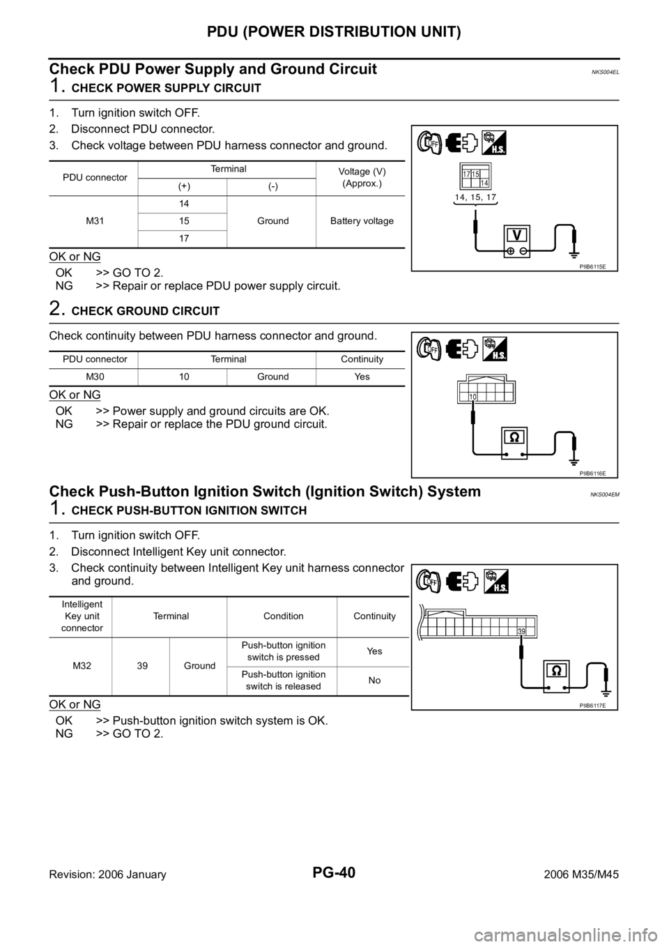
Check PDU Power Supply and Ground CircuitNKS004EL
1. CHECK POWER SUPPLY CIRCUIT
1. Turn ignition switch OFF.
2. Disconnect PDU connector.
3. Check voltage between PDU harness connector and ground.
OK or NG
OK >> GO TO 2.
NG >> Repair or replace PDU power supply circuit.
2. CHECK GROUND CIRCUIT
Check continuity between PDU harness connector and ground.
OK or NG
OK >> Power supply and ground circuits are OK.
NG >> Repair or replace the PDU ground circuit.
Check Push-Button Ignition Switch (Ignition Switch) SystemNKS004EM
1. CHECK PUSH-BUTTON IGNITION SWITCH
1. Turn ignition switch OFF.
2. Disconnect Intelligent Key unit connector.
3. Check continuity between Intelligent Key unit harness connector
and ground.
OK or NG
OK >> Push-button ignition switch system is OK.
NG >> GO TO 2.
PDU connectorTerminal
Voltage (V)
(Approx.)
(+) (-)
M3114
Ground Battery voltage 15
17
PIIB6115E
PDU connector Terminal Continuity
M30 10 Ground Yes
PIIB6116E
Intelligent
Key unit
connectorTerminal Condition Continuity
M32 39 GroundPush-button ignition
switch is pressedYe s
Push-button ignition
switch is releasedNo
PIIB6117E
Page 4869 of 5621

PG-42
PDU (POWER DISTRIBUTION UNIT)
Revision: 2006 January2006 M35/M45
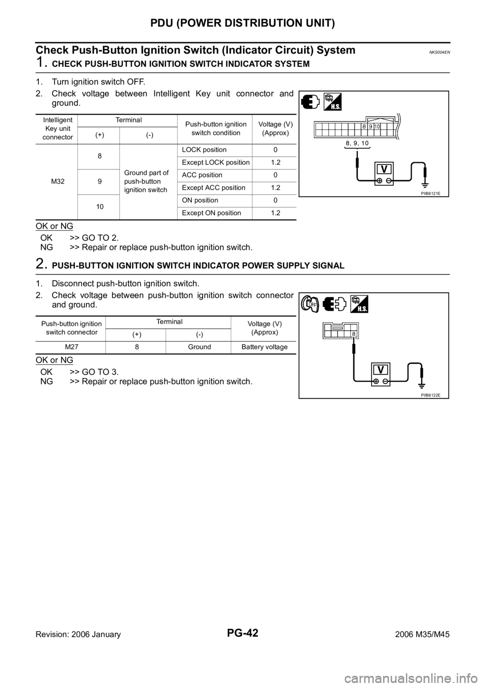
Check Push-Button Ignition Switch (Indicator Circuit) SystemNKS004EN
1. CHECK PUSH-BUTTON IGNITION SWITCH INDICATOR SYSTEM
1. Turn ignition switch OFF.
2. Check voltage between Intelligent Key unit connector and
ground.
OK or NG
OK >> GO TO 2.
NG >> Repair or replace push-button ignition switch.
2. PUSH-BUTTON IGNITION SWITCH INDICATOR POWER SUPPLY SIGNAL
1. Disconnect push-button ignition switch.
2. Check voltage between push-button ignition switch connector
and ground.
OK or NG
OK >> GO TO 3.
NG >> Repair or replace push-button ignition switch.
Intelligent
Key unit
connectorTe r m i n a l
Push-button ignition
switch conditionVoltage (V)
(Approx)
(+) (-)
M328
Ground part of
push-button
ignition switchLOCK position 0
Except LOCK position 1.2
9ACC position 0
Except ACC position 1.2
10ON position 0
Except ON position 1.2
PIIB6121E
Push-button ignition
switch connectorTerminal
Voltage (V)
(Approx)
(+) (-)
M27 8 Ground Battery voltage
PIIB6122E
Page 4870 of 5621

PDU (POWER DISTRIBUTION UNIT)
PG-43
C
D
E
F
G
H
I
J
L
MA
B
PG
Revision: 2006 January2006 M35/M45
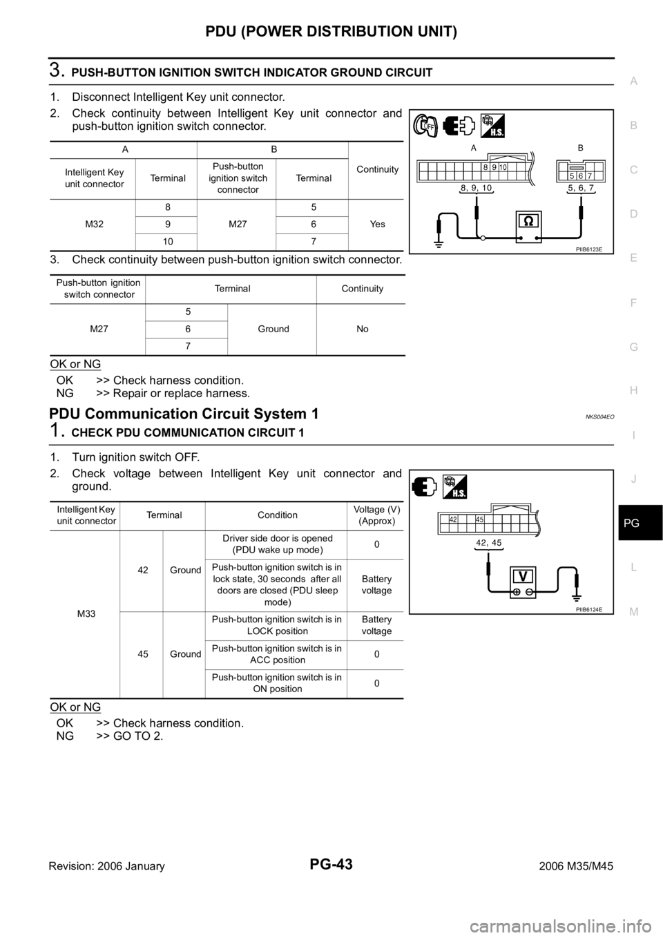
3. PUSH-BUTTON IGNITION SWITCH INDICATOR GROUND CIRCUIT
1. Disconnect Intelligent Key unit connector.
2. Check continuity between Intelligent Key unit connector and
push-button ignition switch connector.
3. Check continuity between push-button ignition switch connector.
OK or NG
OK >> Check harness condition.
NG >> Repair or replace harness.
PDU Communication Circuit System 1NKS004EO
1. CHECK PDU COMMUNICATION CIRCUIT 1
1. Turn ignition switch OFF.
2. Check voltage between Intelligent Key unit connector and
ground.
OK or NG
OK >> Check harness condition.
NG >> GO TO 2.
AB
Continuity
Intelligent Key
unit connectorTerminalPush-button
ignition switch
connectorTe r m i n a l
M328
M275
Ye s 96
10 7
P u s h - b u t t o n i g n i t i o n
switch connectorTerminal Continuity
M275
Ground No 6
7
PIIB6123E
Intelligent Key
unit connectorTerminal ConditionVoltage (V)
(Approx)
M3342 GroundDriver side door is opened
(PDU wake up mode)0
Push-button ignition switch is in
lock state, 30 seconds after all
doors are closed (PDU sleep
mode)Battery
voltage
45 GroundPush-button ignition switch is in
LOCK positionBattery
voltage
Push-button ignition switch is in
ACC position0
Push-button ignition switch is in
ON position0
PIIB6124E
Page 4881 of 5621

PG-54
GROUND
Revision: 2006 January2006 M35/M45
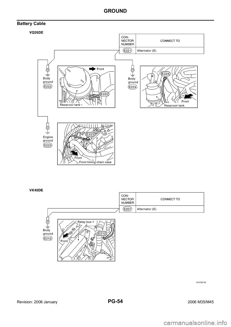
Battery Cable
CKIT0674E