instrument panel INFINITI Q70 HYBRID 2014 User Guide
[x] Cancel search | Manufacturer: INFINITI, Model Year: 2014, Model line: Q70 HYBRID, Model: INFINITI Q70 HYBRID 2014Pages: 522, PDF Size: 4.02 MB
Page 90 of 522

JVO0132X
1. Side ventilator (P.4-33)
2. Meters and gauges (P.2-6)
3. Hazard warning flasher switch (P.6-2)
4. Rear window and outside mirrordefroster switch (P.2-37)
5. Center display (P.4-4)/Navigation sys- tem* (if so equipped)
6. Clock (P.2-49)
7. Center multi-function control panel —Navigation system* (if so
equipped) —
Vehicle information and setting
buttons (P.4-10)
— Bluetooth
®Hands-Free Phone Sys-
tem (P.4-84, P.4-95)
— Audio system (P.4-48)
8. Automatic climate control system (P.4-34)/Forest Air
®system* (P.4-34)
9. Center ventilator (P.4-33)
10. Audio system (P.4-48)
11. Front passenger supplemental air bag (P.1-37)
12. Hood release handle (P.3-16)
13. Fuse box cover (P.8-24)
14. Parking brake —Parking (P.5-18)
15. Push-button ignition switch (P.5-9)
16. Front passenger air bag status light (P.1-44)
17. Climate controlled seat switch (if so equipped) (P.2-46)/Seat heater switch
(if so equipped) (P.2-44)
18. Drive mode select switch (P.5-18)
19. Cigarette lighter and ashtray (P.2-50)
20. Glove box lid release handle (P.2-52)
21. Trunk release power cancel switch (P.3-18)
*: Refer to the separate Navigation System Owner’s Manual.
Instruments and controls2-5
INSTRUMENT PANEL
Page 92 of 522

SIC4318
Speedometer
SPEEDOMETER AND ODOMETER
Speedometer
The speedometer indicates vehicle speed
in miles per hour (MPH) and kilometers per
hour (km/h).
SIC4319
Odometer/twin trip odometer
Odometer/twin trip odometer
The odometer*1and twin trip odometer
*2are displayed on the dot matrix liquid
crystal display when the ignition switch is
in the ON position.
The odometer records the total distance
the vehicle has been driven.
The twin trip odometer records the dis-
tance of individual trips.
Changing the display:
Pushing the TRIP RESET switch
*3on the
right of the combination meter panel
changes the display as follows: TRIP A
?TRIP B ?TRIP A
Resetting the trip odometer:
Pushing the TRIP RESET switch
*3for more
than 1 second resets the trip odometer to
zero.
Average fuel economy and distance to
empty information is also available. (See
“Dot matrix liquid crystal display” (P.2-21)
and “How to use STATUS button” (P.4-10).)
Instruments and controls2-7
Page 103 of 522

2-18Instruments and controls
(P.2-40).
Approaching Vehicle Sound
for Pedestrians (VSP) OFF indicator
light
This light comes on if there is a malfunc-
tion in the Approaching Vehicle Sound for
Pedestrians (VSP) system.
Automatic Transmission (AT)
position indicator light
When the ignition switch is pushed to the
ON position, the indicator shows the
automatic shift position.
In the manual shift mode, when the
transmission does not shift to the selected
gear due to a transmission protection
mode, the AT position indicator light will
blink and a chime will sound.
See “Automatic transmission” (P.5-13) for
further details.
Blind Spot Intervention (BSI)
ON indicator light (green; if so
equipped)
The light comes on in green when the Blind
Spot Intervention (BSI) system is turned
on. The light turns off when the system is
turned off. NOTE:
This light is common with the blind spot
warning light (orange). (See
“Blind Spot
Warning (BSW)/Blind Spot Intervention
(BSI) system warning light” (P.2-11).)
For more details, see “Blind Spot Warning
(BSW) system/Blind Spot Intervention
TM
(BSI) system” (P.5-31).
ECO drive indicator light
When the ignition switch is pushed to the
ON position, the light will come on in
orange, turn green, and then turn off.
When the drive mode select switch is
turned to the ECO mode, the ECO drive
indicator light will illuminate or change its
color depending on the accelerator pedal
operation to help assist the driver to drive
economically. For more details, see “Eco
mode” (P.5-19).
EV indicator light
This illuminates to indicate the vehicle is
being driven powered only by the motor.
Exterior light indicator
This indicator illuminates when the head-
light switch is turned to the AUTO,orposition and the front parking lights, instrument panel lights, rear combination
lights, license plate lights or headlights are
on. The indicator turns off when these
lights are turned off.
Front fog light indicator light
The front fog light indicator light illumi-
nates when the front fog lights are on. (See
“Fog light switch”
(P.2-43).)
Front passenger air bag status
light
The front passenger air bag status light
() will be lit and the passenger front air
bag will be OFF depending on how the front
passenger seat is being used.
For front passenger air bag status light
operation, see “INFINITI Advanced Air Bag
System (front seats)” (P.1-42).
High beam indicator light
This light comes on when the headlight
high beam is on and goes out when the low
beam is selected.
Intelligent Brake Assist (IBA)
off indicator light (if so equipped)
The light illuminates when the Intelligent
Brake Assist (IBA) off switch is pushed to
OFF. This indicates that the Intelligent
Page 113 of 522

2-28Instruments and controls
SIC4327
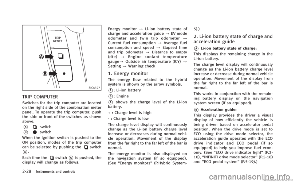
TRIP COMPUTER
Switches for the trip computer are located
on the right side of the combination meter
panel. To operate the trip computer, push
the side or front of the switches as shown
above.
*Aswitch
*Bswitch
When the ignition switch is pushed to the
ON position, modes of the trip computer
can be selected by pushing the
switch
*A.
Each time the
switch*Ais pushed, the
display will change as follows: Energy monitor
?Li-ion battery state of
charge and acceleration guide ?EV mode
odometer and twin trip odometer ?
Current fuel consumption ?Average fuel
consumption and speed ?Elapsed time
and trip odometer ?Distance to empty
(dte) ?Engine coolant temperature
gauge? Outside air temperature (ICY) ?
Setting ?Warning check
1. Energy monitor
The energy flow related to the hybrid
system is shown by the arrow symbols.
*A: Li-ion battery
*B: Engine
*Ashows the charge level of the Li-ion
battery.
+ : Charge level is high
- : Charge level is low
The charge level display will continuously
change as the Li-ion battery charge level
increase or decreases during normal vehi-
cle operation. Movement of the display
from the far right to the far left of the bar is
normal.
The energy monitor is also displayed on
the navigation system (if so equipped).
(See “Energy monitors” (P.Hybrid System- 5).)
2. Li-ion battery state of charge and
acceleration guide
*ALi-ion battery state of charge:
This displays the remaining charge in the
Li-ion battery.
The charge level display will continuously
change as the Li-ion battery charge level
increase or decrease during normal vehicle
operation. Movement of the display from
the far right to the far left of the bar is
normal.
This works in conjunction with the remain-
ing battery display on the navigation
system screen (if so equipped).
*BAcceleration guide:
This display provides the driver a visual
display of how efficiently the vehicle is
being driven based on accelerator pedal
position. When the drive mode is set to
ECO using the drive mode selector, the
acceleration guide operates with the ECO
drive indicator and ECO pedal (if so
equipped) to help you improve fuel econ-
omy. (See “ECO drive indicator light” (P.2-
18), “INFINITI drive mode selector” (P.5-18)
and “ECO pedal system” (P.5-19).)
Page 119 of 522

2-34Instruments and controls
INFINITI VEHICLE IMMOBILIZER
SYSTEM
The INFINITI Vehicle Immobilizer System
will not allow the hybrid system to start
without the use of the registered Intelligent
Key.Never leave these keys in the vehicle.
FCC Notice:
For USA:
This device complies with Part 15 of the
FCC Rules. Operation is subject to the
following two conditions: (1) This device
may not cause harmful interference, and
(2) this device must accept any interfer-
ence received, including interference that
may cause undesired operation.
NOTE:
Changes or modifications not expressly
approved by the party responsible for
compliance could void the user’s authority
to operate the equipment.
For Canada:
This device complies with RSS-210 of
Industry Canada. Operation is subject to
the following two conditions: (1) this
device may not cause interference, and
(2) this device must accept any interfer-
ence, including interference that may cause undesired operation of the device.
SIC2045
Security indicator light
The security indicator light is located on
the meter panel. It indicates the status of
the INFINITI Vehicle Immobilizer System.
The light blinks after the ignition switch
was in the LOCK, ACC or OFF position. This
function indicates the security systems
equipped on the vehicle are operational.
If the INFINITI Vehicle Immobilizer System
is malfunctioning, this light will remain on
while the ignition switch is in the ON
position.
Page 124 of 522

SIC3268
Autolight system
The autolight system allows the headlights
to be set so they turn on and off
automatically.
To set the autolight system:
1. Make sure the headlight switch is in theAUTO position
*1.
2. Push the ignition switch to the ON position.
3. The autolight system automatically turns the headlights on and off.
To turn the autolight system off, turn the
switch to the OFF,
orposition. The autolight system can turn on the
headlights automatically when it is dark
and turn off the headlights when it is light.
For US models: The headlights will also be
turned on automatically at twilight or in
rainy weather (when the windshield wiper
is operated continuously).
If the ignition switch is pushed to the OFF
position and one of the doors is opened
and this condition is continued, the head-
lights remain on for 5 minutes.
Automatic headlights off delay:
You can keep the headlights on for up to
180 seconds after you push the ignition
switch to OFF and open any door then close
all the doors.
You can adjust the period of the automatic
headlights off delay from 0 seconds (OFF)
to 180 seconds. The factory default setting
is 45 seconds.
For automatic headlights off delay setting,
see “Comfort settings” (P.4-21).
SAA0642A
Be sure not to put anything on top of the
photo sensor
*Alocated on the top of the
instrument panel. The photo sensor con-
trols the autolight; if it is covered, the
photo sensor reacts as if it is dark and the
headlights will illuminate.
Instruments and controls2-39
Page 127 of 522

2-42Instruments and controls
SIC4331
SIC3270
Instrument brightness control
The instrument brightness control switch
can be operated when the ignition switch
is in the ON position. When the switch is
operated, the dot matrix liquid crystal
display switches to the brightness adjust-
ment mode.
Push the upper switch
*Ato brighten the
instrument panel lights. The bar
*1moves
to the + side. When reaching the maximum
brightness, “MAX”appears on the display
*2.
Push the lower switch
*Bto dim the
instrument panel lights. The bar
*1moves
to the −side. When reaching the minimum
brightness, “MIN”appears on the display
*3. However, “MIN” does not appear
during the nighttime.
The dot matrix liquid crystal display
returns to the normal display under the
following conditions:
. when the instrument brightness control
switch is not operated for more than 5
seconds.
. when the side or front of the
switch
orswitch on the right side of the
combination meter panel is pushed.
Page 144 of 522

Depending on the environment or driving
conditions, the auto reverse function may
be activated if an impact or load similar to
something being caught in the moonroof
occurs.
If the moonroof does not operate
If the moonroof does not operate properly,
perform the following procedure to initi-
alize the moonroof operation system.
1. If the moonroof is open, close it fully byrepeatedly pushing the moonroof
switch to the close position
*1to tilt
the moonroof up.
2. Push and hold the switch to the close position
*1.
3. Release the moonroof switch after the moonroof moves slightly up and down.
4. Push and hold the switch to the open position
*2to fully tilt the moonroof
down.
5. Check if the moonroof switch operates normally.
If the moonroof does not operate properly
after performing the procedure above, have
your vehicle checked by an INFINITI retailer.
CAUTION
. To avoid personal injury, keep your
hands, fingers and head away from the
sunshade arm, arm rail and sunshade
inlet port.
. Do not allow children near the rear
sunshade system. They could be injured.
. Do not place objects on or near the rear
sunshade. This could cause improper
operation or damage it.
. Do not pull or push the rear sunshade.
This could cause improper operation or
damage it.
SIC4349
The rear sunshade operates when the
power ignition is in the ON position.
The rear sunshade switch is located on the
instrument panel.
To raise and lower the sunshade, push the
switch.
The switch need not be held.
When the shift lever is moved to the “R”
(Reverse) position, the rear sunshade
automatically lowers.
Instruments and controls2-59
REAR SUNSHADE (if so equipped)
Page 169 of 522

3-16Pre-driving checks and adjustments
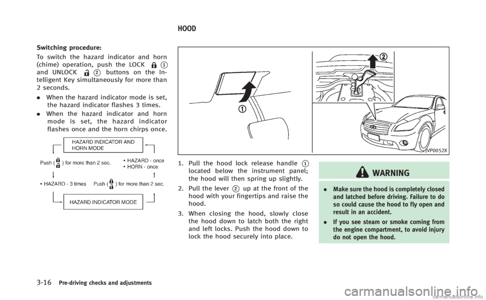
Switching procedure:
To switch the hazard indicator and horn
(chime) operation, push the LOCK
*1and UNLOCK*2buttons on the In-
telligent Key simultaneously for more than
2 seconds.
. When the hazard indicator mode is set,
the hazard indicator flashes 3 times.
. When the hazard indicator and horn
mode is set, the hazard indicator
flashes once and the horn chirps once.
JVP0052X
1. Pull the hood lock release handle*1located below the instrument panel;
the hood will then spring up slightly.
2. Pull the lever
*2up at the front of the
hood with your fingertips and raise the
hood.
3. When closing the hood, slowly close the hood down to latch both the right
and left locks. Push the hood down to
lock the hood securely into place.
WARNING
. Make sure the hood is completely closed
and latched before driving. Failure to do
so could cause the hood to fly open and
result in an accident.
. If you see steam or smoke coming from
the engine compartment, to avoid injury
do not open the hood.
HOOD
Page 170 of 522

WARNING
.Do not drive with the trunk lid open. This
could allow dangerous exhaust gases to
be drawn into the vehicle. See “Exhaust
gas (carbon monoxide)” (P.5-3).
. Closely supervise children when they are
around cars to prevent them from play-
ing and becoming locked in the trunk
where they could be seriously injured.
Keep the car locked, with the trunk
closed, when not in use, and prevent
children’s access to Intelligent Keys.
SPA2734
TRUNK LID RELEASE SWITCH
The trunk lid release switch*Ais located
on the instrument panel.
To open the trunk lid, push the release
switch. To close, push the trunk lid down.
You can open the trunk lid with Intelligent
Key. (See “Intelligent Key system” (P.3-6)
or “Remote keyless entry system” (P.3-13).)
If the trunk lid does not unlock, push the
trunk open request switch and manually lift
the trunk lid if:
. there is snow on the trunk lid.
. a heavy object such as rear spoiler is
attached to the trunk lid. .
the trunk lid is frozen.
Pre-driving checks and adjustments3-17
TRUNK LID