warning INFINITI Q70 HYBRID 2015 First Responder´s
[x] Cancel search | Manufacturer: INFINITI, Model Year: 2015, Model line: Q70 HYBRID, Model: INFINITI Q70 HYBRID 2015Pages: 42, PDF Size: 5.73 MB
Page 2 of 42
Foreword
This
manual describes first response operations and related warnings and cautions for this vehicle.
This vehicle is equipped with a high voltage battery pack. Failure to follow recommended practices
during emergency responses will cause death or serious personal injury.
Please read this manual in advance in order to understand the features of this vehicle and to help you deal
with incidents involving this vehicle. Follow the procedures in order to help assure a successful first
response operation.
This manual is periodically updated. If you are not viewing this manual on the Infiniti web site, we urge you to
go to www.infinitiusa.com orwww.infiniti-techinfo.com to make sure you have the most recent version of this
manual.
INFINITI
EMERGENCY CONTACT INFORMATION
• Infiniti Consumer Affairs: 1-800-662-6200 (US) or 1-800-361-4792 (Canada)
• Hours of operation are 8am - 5pm (Monday-Friday) Eastern, Central and Pacific time zones
IMPORTANT INFORMATION ABOUT THIS MANUAL
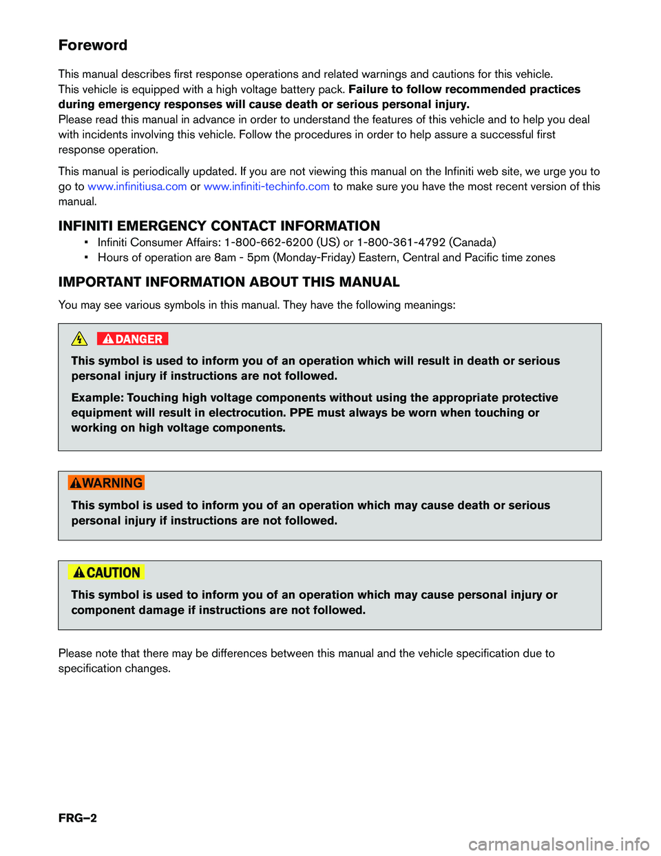
You may see various symbols in this manual. They have the following meanings: DANGER
This symbol is used to inform you of an operation which will result in death or serious
personal
injury if instructions are not followed.
Example: Touching high voltage components without using the appropriate protective
equipment will result in electrocution. PPE must always be worn when touching or
working on high voltage components. This symbol is used to inform you of an operation which may cause death or serious
personal
injury if instructions are not followed. This symbol is used to inform you of an operation which may cause personal injury or
component
damage if instructions are not followed.
Please note that there may be differences between this manual and the vehicle specification due to
specification changes.
FRG–2
Page 3 of 42
Table of Contents
FOREWORD
. . . . . . . . . . . . . . . . . . . . . . . . . . . . . . . . . . . . . . . . . . . . . . . . . . . . . . . . . . . . . . . . . . . FRG–2
INFINITI EMERGENCY CONTACT INFORMATION . . . . . . . . . . . . . . . . . . . . . . . . . . . . . . . . . . . FRG–2
IMPORTANT INFORMATION ABOUT THIS MANUAL . . . . . . . . . . . . . . . . . . . . . . . . . . . . . . . . . FRG–2
1. ABOUT THE INFINITI Q70 HYBRID . . . . . . . . . . . . . . . . . . . . . . . . . . . . . . . . . . . . . . . . . . . . . . . FRG–5
1-1 Q70 HYBRID IDENTIFICATION . . . . . . . . . . . . . . . . . . . . . . . . . . . . . . . . . . . . . . . . . . . . . . FRG–61-1.1 EXTERIOR AND ENGINE COMPARTMENT . . . . . . . . . . . . . . . . . . . . . . . . . . . . . . . FRG–6
1-1.2 INTERIOR . . . . . . . . . . . . . . . . . . . . . . . . . . . . . . . . . . . . . . . . . . . . . . . . . . . . . . . . . FRG–7
1-2 VEHICLE IDENTIFICATION NUMBER (VIN) LAYOUT . . . . . . . . . . . . . . . . . . . . . . . . . . . . . FRG–8
1-3 WARNING AND INDICATOR LAMP INFORMATION . . . . . . . . . . . . . . . . . . . . . . . . . . . . . . FRG–9
2. BASIC HIGH VOLTAGE SYSTEM AND 12-VOLT SYSTEM INFORMATION . . . . . . . . . . . . . . . FRG–10 2-1 BATTERY INFORMATION . . . . . . . . . . . . . . . . . . . . . . . . . . . . . . . . . . . . . . . . . . . . . . . . . FRG–102-1.1 12-VOLT BATTERY . . . . . . . . . . . . . . . . . . . . . . . . . . . . . . . . . . . . . . . . . . . . . . . . . FRG–10
2-1.2 HIGH VOLTAGE BATTERY . . . . . . . . . . . . . . . . . . . . . . . . . . . . . . . . . . . . . . . . . . . FRG–10
2-2 HIGH VOLTAGE-RELATED AND 12-VOLT-RELATED COMPONENT LOCATIONS AND DESCRIPTIONS . . . . . . . . . . . . . . . . . . . . . . . . . . . . . . . . . . . . . . . . . . . . . . . . . . . . FRG–11
2-3 HIGH VOLTAGE BATTERY PACK SPECIFICATIONS . . . . . . . . . . . . . . . . . . . . . . . . . . . . FRG–12
2-4 HIGH VOLTAGE SAFETY MEASURES . . . . . . . . . . . . . . . . . . . . . . . . . . . . . . . . . . . . . . . FRG–13 2-4.1 WARNING LABELS . . . . . . . . . . . . . . . . . . . . . . . . . . . . . . . . . . . . . . . . . . . . . . . . . FRG–13
2-5 HIGH VOLTAGE SAFETY SYSTEM . . . . . . . . . . . . . . . . . . . . . . . . . . . . . . . . . . . . . . . . . . FRG–14
2-6 HIGH VOLTAGE CIRCUIT SHUT-OFF SYSTEM . . . . . . . . . . . . . . . . . . . . . . . . . . . . . . . . FRG–15
2-7 PREVENTING ELECTRICAL SHOCK . . . . . . . . . . . . . . . . . . . . . . . . . . . . . . . . . . . . . . . . FRG–15
2-8 EMERGENCY MEDICAL EQUIPMENT . . . . . . . . . . . . . . . . . . . . . . . . . . . . . . . . . . . . . . . FRG–15
3. EMERGENCY RESPONSE STEPS . . . . . . . . . . . . . . . . . . . . . . . . . . . . . . . . . . . . . . . . . . . . . FRG–16 3-1 PREPARATION ITEMS . . . . . . . . . . . . . . . . . . . . . . . . . . . . . . . . . . . . . . . . . . . . . . . . . . . FRG–173-1.1
PERSONAL PROTECTIVE EQUIPMENT (PPE) PROTECTIVE WEAR CONTROL. . . FRG–17
3-1.2 DAILY INSPECTION . . . . . . . . . . . . . . . . . . . . . . . . . . . . . . . . . . . . . . . . . . . . . . . . FRG–18
3-1.3 INSULATED TOOLS . . . . . . . . . . . . . . . . . . . . . . . . . . . . . . . . . . . . . . . . . . . . . . . . FRG–18
3-2 VEHICLE IMMOBILIZATION AND STABILIZATION . . . . . . . . . . . . . . . . . . . . . . . . . . . . . . FRG–18
3-3 HOW TO HANDLE A DAMAGED VEHICLE AT AN ACCIDENT SCENE . . . . . . . . . . . . . FRG–19 3-3.1 HIGH VOLTAGE SYSTEM SHUT-DOWN PROCEDURE . . . . . . . . . . . . . . . . . . . . FRG–20
3-3.2 WATER SUBMERSION . . . . . . . . . . . . . . . . . . . . . . . . . . . . . . . . . . . . . . . . . . . . . . FRG–29
3-3.3 VEHICLE FIRE . . . . . . . . . . . . . . . . . . . . . . . . . . . . . . . . . . . . . . . . . . . . . . . . . . . . . FRG–29
FRG–3
Page 9 of 42
1-3 Warning and Indicator Lamp Information
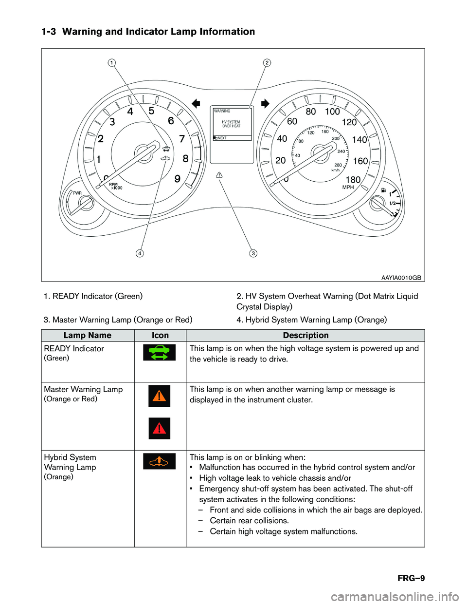
1. READY Indicator (Green) 2. HV System Overheat Warning (Dot Matrix Liquid
Crystal Display)
3. Master Warning Lamp (Orange or Red) 4. Hybrid System Warning Lamp (Orange)Lamp Name Icon
Description
READ
Y Indicator
(Green) This lamp is on when the high voltage system is powered up and
the
vehicle is ready to drive.
Master Warning Lamp
(Orange or Red) This lamp is on when another warning lamp or message is
displayed
in the instrument cluster.
Hybrid System
Warning Lamp
(Orange) This lamp is on or blinking when:
•
Malfunction has occurred in the hybrid control system and/or
• High voltage leak to vehicle chassis and/or
• Emergency shut-off system has been activated. The shut-off system activates in the following conditions:
– Front and side collisions in which the air bags are deployed.
– Certain rear collisions.
– Certain high voltage system malfunctions. AAYIA0010GB
FRG–9
Page 13 of 42
2-4 High Voltage Safety Measures
Circuit insulation
The high voltage positive (+) and negative (-) circuits are insulated from the
metal chassis.
Reducing the risk of
electrocution The high voltage components and harnesses have insulated cases or
orange-colored coverings which provide insulation and easy identification.
The high voltage battery case is electrically connected to the vehicle ground.
This connection helps protect the vehicle occupants and emergency responders
from high voltage electrical shock.
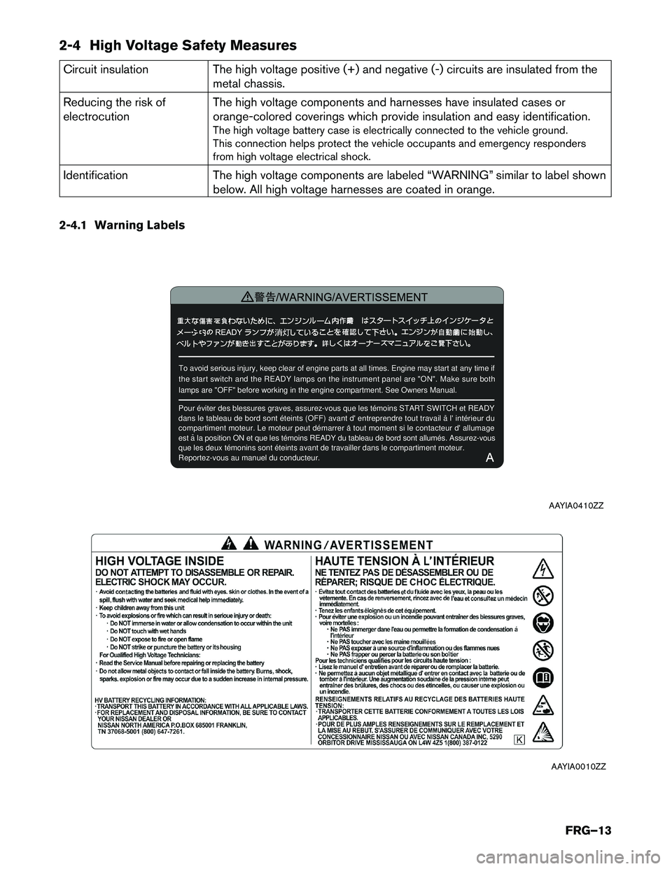
Identification The high voltage components are labeled “WARNING” similar to label shown
below. All high voltage harnesses are coated in orange.
2-4.1 Warning Labels To avoid serious injury, keep clear of engine parts at all times. Engine\
may start at any time if
t
he start switch and the READY lamps on the instrument panel are "ON". Make sure both
lamps are "OFF" before working in the engine compartment. See Owners Man\
ual. ¾¯¸æ/WARNING/AVERTISSEMENT ÖØ ´ó
ÏûµÆ
Pour éviter des blessures graves, assurez-vous que les témoins STA\
RT SWITCH et READY
d
ans le tableau de bord sont éteints (OFF) avant d' entreprendre tout travail a l' intérieur du
compartiment moteur. Le moteur peut démarrer a tout moment si le contacteur d' allumage
est a la position ON et que les témoins READY du tableau de bord sont allumés. Assurez-vous
que les deux témonins sont éteints avant de travailler dans le com\
partiment moteur.
Reportez-vous au manuel du conducteur. ÉË º¦
¶¯³ö
Ïê ÀÀ
¸º
×÷ Òµ ʱ
È· ÈÏ ×Ô ¶¯ µÄʼ ¶¯ READY
A
AAYIA0410ZZ AAYIA0010ZZ
FRG–13
Page 14 of 42
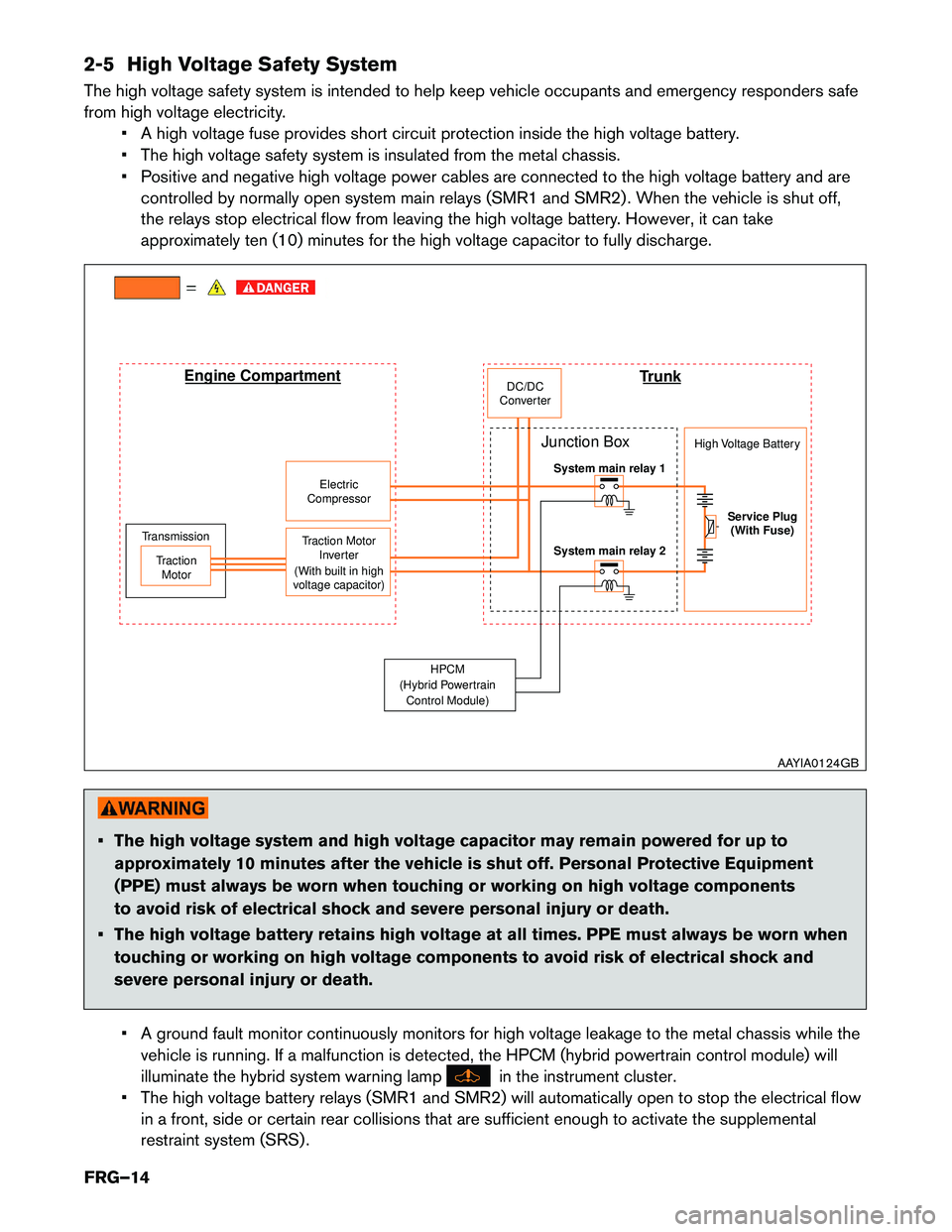
2-5 High Voltage Safety System
The
high voltage safety system is intended to help keep vehicle occupants and emergency responders safe
from high voltage electricity. • A high voltage fuse provides short circuit protection inside the high voltage battery.
• The high voltage safety system is insulated from the metal chassis.
• Positive and negative high voltage power cables are connected to the high voltage battery and arecontrolled by normally open system main relays (SMR1 and SMR2) . When the vehicle is shut off,
the relays stop electrical flow from leaving the high voltage battery. However, it can take
approximately ten (10) minutes for the high voltage capacitor to fully discharge. • The high voltage system and high voltage capacitor may remain powered for up to
approximately
10 minutes after the vehicle is shut off. Personal Protective Equipment
(PPE) must always be worn when touching or working on high voltage components
to avoid risk of electrical shock and severe personal injury or death.
• The high voltage battery retains high voltage at all times. PPE must always be worn when touching or working on high voltage components to avoid risk of electrical shock and
severe personal injury or death.
• A ground fault monitor continuously monitors for high voltage leakage to the metal chassis while the vehicle is running. If a malfunction is detected, the HPCM (hybrid powertrain control module) will
illuminate the hybrid system warning lamp in the instrument cluster.
•
The high voltage battery relays (SMR1 and SMR2) will automatically open to stop the electrical flow
in a front, side or certain rear collisions that are sufficient enough to activate the supplemental
restraint system (SRS) . Trunk
J
unction Box High Voltage Battery
System main relay 1
Service Plug (With Fuse)
System main relay 2
Transmission
Traction Motor Traction Motor
Inverter
(With built in high
voltage capacitor) Electric
Compressor DC/DC
Converter
Engine Compartment
HPCM
(Hybrid Powertrain Control Module) AAYIA0124GB
FRG–14