seats INFINITI QX4 2001 Factory Service Manual
[x] Cancel search | Manufacturer: INFINITI, Model Year: 2001, Model line: QX4, Model: INFINITI QX4 2001Pages: 2395, PDF Size: 43.2 MB
Page 375 of 2395

SFA755B
2. Pack drive flange groove with grease, apply grease to O-ring
(two places) and mating surface of drive flange, and install
flange.
3. Install snap ring.
SFA759B
4. Install hub cap using a suitable tool.
Do not reuse hub cap. When installing, replace it with a new
one.
FA858
DISASSEMBLYNBAX0010IRemove grease seal and bearing outer races with suitable
brass bar.
INSPECTIONNBAX0011Thoroughly clean wheel bearings and wheel hub.
Wheel BearingNBAX0011S01IMake sure wheel bearing rolls freely and is free from noise,
crack, pitting and wear.
Wheel HubNBAX0011S02ICheck wheel hub for crack by using a magnetic exploration or
dyeing test.
SFA197-A
ASSEMBLYNBAX00121. Install bearing outer race with Tool until it seats in hub.
FRONT AXLE
Wheel Hub and Rotor Disc (Cont'd)
AX-8
Page 474 of 2395
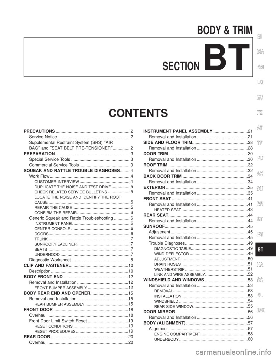
BODY & TRIM
SECTION
BT
CONTENTS
PRECAUTIONS...............................................................2
Service Notice..............................................................2
Supplemental Restraint System (SRS)²AIR
BAG²and²SEAT BELT PRE-TENSIONER²...............2
PREPARATION...............................................................3
Special Service Tools ..................................................3
Commercial Service Tools ...........................................3
SQUEAK AND RATTLE TROUBLE DIAGNOSES.........4
Work Flow ....................................................................4
CUSTOMER INTERVIEW...........................................4
DUPLICATE THE NOISE AND TEST DRIVE................5
CHECK RELATED SERVICE BULLETINS...................5
LOCATE THE NOISE AND IDENTIFY THE ROOT
CAUSE
.....................................................................5
REPAIR THE CAUSE.................................................5
CONFIRM THE REPAIR.............................................6
Generic Squeak and Rattle Troubleshooting ..............6
INSTRUMENT PANEL................................................6
CENTER CONSOLE..................................................6
DOORS.....................................................................6
TRUNK.....................................................................7
SUNROOF/HEADLINER.............................................7
SEATS......................................................................7
UNDERHOOD...........................................................7
Diagnostic Worksheet ..................................................8
CLIP AND FASTENER..................................................10
Description .................................................................10
BODY FRONT END.......................................................12
Removal and Installation ...........................................12
FRONT BUMPER ASSEMBLY..................................12
BODY REAR END AND OPENER................................15
Removal and Installation ...........................................15
REAR BUMPER ASSEMBLY....................................15
FRONT DOOR...............................................................18
Overhaul ....................................................................18
Front Door Limit Switch Reset ..................................19
RESET CONDITIONS..............................................19
RESET PROCEDURES............................................19
REAR DOOR.................................................................20
Overhaul ....................................................................20INSTRUMENT PANEL ASSEMBLY.............................21
Removal and Installation ...........................................21
SIDE AND FLOOR TRIM...............................................28
Removal and Installation ...........................................28
DOOR TRIM...................................................................30
Removal and Installation ...........................................30
ROOF TRIM...................................................................32
Removal and Installation ...........................................32
BACK DOOR TRIM.......................................................34
Removal and Installation ...........................................34
EXTERIOR.....................................................................35
Removal and Installation ...........................................35
FRONT SEAT................................................................41
Removal and Installation ...........................................41
HEATED SEAT........................................................43
REAR SEAT...................................................................44
Removal and Installation ...........................................44
SUNROOF......................................................................45
Adjustment .................................................................45
Removal and Installation ...........................................45
Trouble Diagnoses.....................................................49
DIAGNOSTIC TABLE................................................49
WIND DEFLECTOR.................................................49
ADJUSTMENT.........................................................50
DRAIN HOSES........................................................51
WEATHERSTRIP.....................................................51
LINK AND WIRE ASSEMBLY....................................52
WINDSHIELD AND WINDOWS....................................53
Removal and Installation ...........................................53
REMOVAL...............................................................53
INSTALLATION........................................................53
WINDSHIELD..........................................................54
REAR SIDE WINDOW..............................................55
DOOR MIRROR.............................................................56
Removal and Installation ...........................................56
BODY (ALIGNMENT)....................................................57
Alignment ...................................................................57
ENGINE COMPARTMENT........................................58
UNDERBODY..........................................................60
GI
MA
EM
LC
EC
FE
AT
TF
PD
AX
SU
BR
ST
RS
HA
SC
EL
IDX
Page 480 of 2395
TRUNK=NBBT0025S04Trunk noises are often caused by a loose jack or loose items put into the trunk by the owner.
In addition look for:
1. Trunk lid bumpers out of adjustment
2. Trunk lid striker out of adjustment
3. The trunk lid torsion bars knocking together
4. A loose license plate or bracket
Most of these incidents can be repaired by adjusting, securing or insulating the item(s) or component(s) caus-
ing the noise.
SUNROOF/HEADLINERNBBT0025S05Noises in the sunroof/headliner area can often be traced to one of the following:
1. Sunroof lid, rail, linkage or seals making a rattle or light knocking noise
2. Sunvisor shaft shaking in the holder
3. Front or rear windshield touching headliner and squeaking
Again, pressing on the components to stop the noise while duplicating the conditions can isolate most of these
incidents. Repairs usually consist of insulating with felt cloth tape.
SEATSNBBT0025S06When isolating seat noises it's important to note the position the seat is in and the load placed on the seat
when the noise is present. These conditions should be duplicated when verifying and isolating the cause of
the noise.
Cause of seat noise include:
1. Headrest rods and holders
2. A squeak between the seat pad cushion and frame
3. The rear seat back lock and bracket
These noises can be isolated by moving or pressing on the suspected components while duplicating the con-
ditions under which the noise occurs. Most of these incidents can be repaired by repositioning the component
or applying urethane tape to the contact area.
UNDERHOODNBBT0025S07Some interior noises may be caused by components under the hood or on the engine wall. The noise is then
transmitted into the passenger compartment.
Causes of transmitted underhood noises include:
1. Any component mounted to the engine wall
2. Components that pass through the engine wall
3. Engine wall mounts and connectors
4. Loose radiator mounting pins
5. Hood bumpers out of adjustment
6. Hood striker out of adjustment
These noises can be difficult to isolate since they cannot be reached from the interior of the vehicle. The best
method is to secure, move or insulate one component at a time and test drive the vehicle. Also, engine RPM
or load can be changed to isolate the noise. Repairs can usually be made by moving, adjusting, securing, or
insulating the component causing the noise.
GI
MA
EM
LC
EC
FE
AT
TF
PD
AX
SU
BR
ST
RS
HA
SC
EL
IDX
SQUEAK AND RATTLE TROUBLE DIAGNOSES
Generic Squeak and Rattle Troubleshooting (Cont'd)
BT-7
Page 501 of 2395

Removal and InstallationNBBT0009CAUTION:
Wrap the tip of flat-bladed screwdriver with a cloth when removing metal clips from garnishes.
1. Remove front and rear seats. Refer to ªFRONT SEATº and ªREAR SEATº for details, BT-41, BT-44.
2. Remove front and rear seat belts. Refer to RS-4 and RS-5, ªFront Seat Beltº and ªRear Seat Beltº for
details.
3. Remove front and rear kicking plates.
4. Remove dash side lower finishers.
5. Remove front and rear body side welts.
6. Remove front pillar garnishes.
7. Remove center assist grips.
8. Remove center pillar lower garnishes.
9. Remove center pillar upper garnishes.
10. Remove rear gate kicking plate.
11. Remove rear net hooks.
12. Remove tonneau cover assembly and rear parcel holder.
13. Remove rear side lower garnishes.
14. Remove rear side upper garnishes.
SBT694
SIDE AND FLOOR TRIM
Removal and Installation
BT-28
Page 505 of 2395

Removal and InstallationNBBT00111. Remove front and rear seats. Refer to ªFRONT SEATº and ªREAR SEATº for details, BT-41, BT-44.
2. Remove front and rear seat belts. Refer to RS-4 and RS-5, ªFront Seat Beltº and ªRear Seat Beltº for
details.
3. Remove body side trim. Refer to ªSIDE AND FLOOR TRIMº for details, BT-28.
4. Remove roof console assembly.
5. Remove inside mirror assembly.
6. Remove sun visors.
7. Remove interior lamp assembly and luggage room lamp assembly.
8. Remove assist grips.
9. Remove clips securing headlining.
10. Remove rear roof garnish.
11. Remove headlining from vehicle through either back door.
ROOF TRIM
Removal and Installation
BT-32
Page 858 of 2395
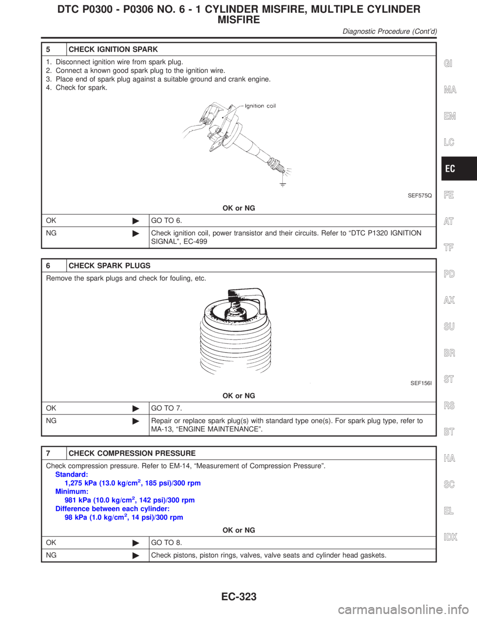
5 CHECK IGNITION SPARK
1. Disconnect ignition wire from spark plug.
2. Connect a known good spark plug to the ignition wire.
3. Place end of spark plug against a suitable ground and crank engine.
4. Check for spark.
SEF575Q
OK or NG
OK©GO TO 6.
NG©Check ignition coil, power transistor and their circuits. Refer to ªDTC P1320 IGNITION
SIGNALº, EC-499
6 CHECK SPARK PLUGS
Remove the spark plugs and check for fouling, etc.
SEF156I
OK or NG
OK©GO TO 7.
NG©Repair or replace spark plug(s) with standard type one(s). For spark plug type, refer to
MA-13, ªENGINE MAINTENANCEº.
7 CHECK COMPRESSION PRESSURE
Check compression pressure. Refer to EM-14, ªMeasurement of Compression Pressureº.
Standard:
1,275 kPa (13.0 kg/cm
2, 185 psi)/300 rpm
Minimum:
981 kPa (10.0 kg/cm
2, 142 psi)/300 rpm
Difference between each cylinder:
98 kPa (1.0 kg/cm
2, 14 psi)/300 rpm
OK or NG
OK©GO TO 8.
NG©Check pistons, piston rings, valves, valve seats and cylinder head gaskets.
GI
MA
EM
LC
FE
AT
TF
PD
AX
SU
BR
ST
RS
BT
HA
SC
EL
IDX
DTC P0300 - P0306 NO.6-1CYLINDER MISFIRE, MULTIPLE CYLINDER
MISFIRE
Diagnostic Procedure (Cont'd)
EC-323
Page 1644 of 2395
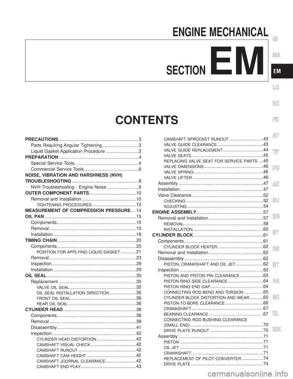
ENGINE MECHANICAL
SECTION
EM
CONTENTS
PRECAUTIONS...............................................................3
Parts Requiring Angular Tightening .............................3
Liquid Gasket Application Procedure ..........................3
PREPARATION...............................................................4
Special Service Tools ..................................................4
Commercial Service Tools ...........................................6
NOISE, VIBRATION AND HARSHNESS (NVH)
TROUBLESHOOTING.....................................................8
NVH Troubleshooting - Engine Noise .........................9
OUTER COMPONENT PARTS.....................................10
Removal and Installation ...........................................10
TIGHTENING PROCEDURES...................................12
MEASUREMENT OF COMPRESSION PRESSURE....14
OIL PAN.........................................................................15
Components...............................................................15
Removal .....................................................................15
Installation ..................................................................18
TIMING CHAIN..............................................................20
Components...............................................................20
POSITION FOR APPLYING LIQUID GASKET............21
Removal .....................................................................23
Inspection...................................................................29
Installation ..................................................................29
OIL SEAL.......................................................................35
Replacement ..............................................................35
VALVE OIL SEAL.....................................................35
OIL SEAL INSTALLATION DIRECTION.....................36
FRONT OIL SEAL....................................................36
REAR OIL SEAL......................................................36
CYLINDER HEAD..........................................................38
Components...............................................................38
Removal .....................................................................39
Disassembly...............................................................41
Inspection...................................................................42
CYLINDER HEAD DISTORTION...............................42
CAMSHAFT VISUAL CHECK....................................42
CAMSHAFT RUNOUT..............................................42
CAMSHAFT CAM HEIGHT.......................................42
CAMSHAFT JOURNAL CLEARANCE........................42
CAMSHAFT END PLAY............................................43
CAMSHAFT SPROCKET RUNOUT...........................43
VALVE GUIDE CLEARANCE....................................43
VALVE GUIDE REPLACEMENT................................44
VALVE SEATS.........................................................45
REPLACING VALVE SEAT FOR SERVICE PARTS....45
VALVE DIMENSIONS...............................................46
VALVE SPRING.......................................................46
VALVE LIFTER........................................................46
Assembly ...................................................................47
Installation ..................................................................47
Valve Clearance.........................................................52
CHECKING.............................................................52
ADJUSTING............................................................54
ENGINE ASSEMBLY.....................................................57
Removal and Installation ...........................................57
REMOVAL...............................................................58
INSTALLATION........................................................60
CYLINDER BLOCK.......................................................61
Components...............................................................61
CYLINDER BLOCK HEATER....................................62
Removal and Installation ...........................................62
Disassembly...............................................................62
PISTON, CRANKSHAFT AND OIL JET......................62
Inspection...................................................................63
PISTON AND PISTON PIN CLEARANCE..................63
PISTON RING SIDE CLEARANCE............................64
PISTON RING END GAP..........................................64
CONNECTING ROD BEND AND TORSION...............65
CYLINDER BLOCK DISTORTION AND WEAR...........65
PISTON-TO-BORE CLEARANCE..............................66
CRANKSHAFT.........................................................67
BEARING CLEARANCE...........................................67
CONNECTING ROD BUSHING CLEARANCE
(SMALL END)
..........................................................70
DRIVE PLATE RUNOUT..........................................70
Assembly ...................................................................71
PISTON..................................................................71
OIL JET..................................................................71
CRANKSHAFT.........................................................71
REPLACEMENT OF PILOT CONVERTER.................74
DRIVE PLATE.........................................................74
GI
MA
LC
EC
FE
AT
TF
PD
AX
SU
BR
ST
RS
BT
HA
SC
EL
IDX
Page 1688 of 2395
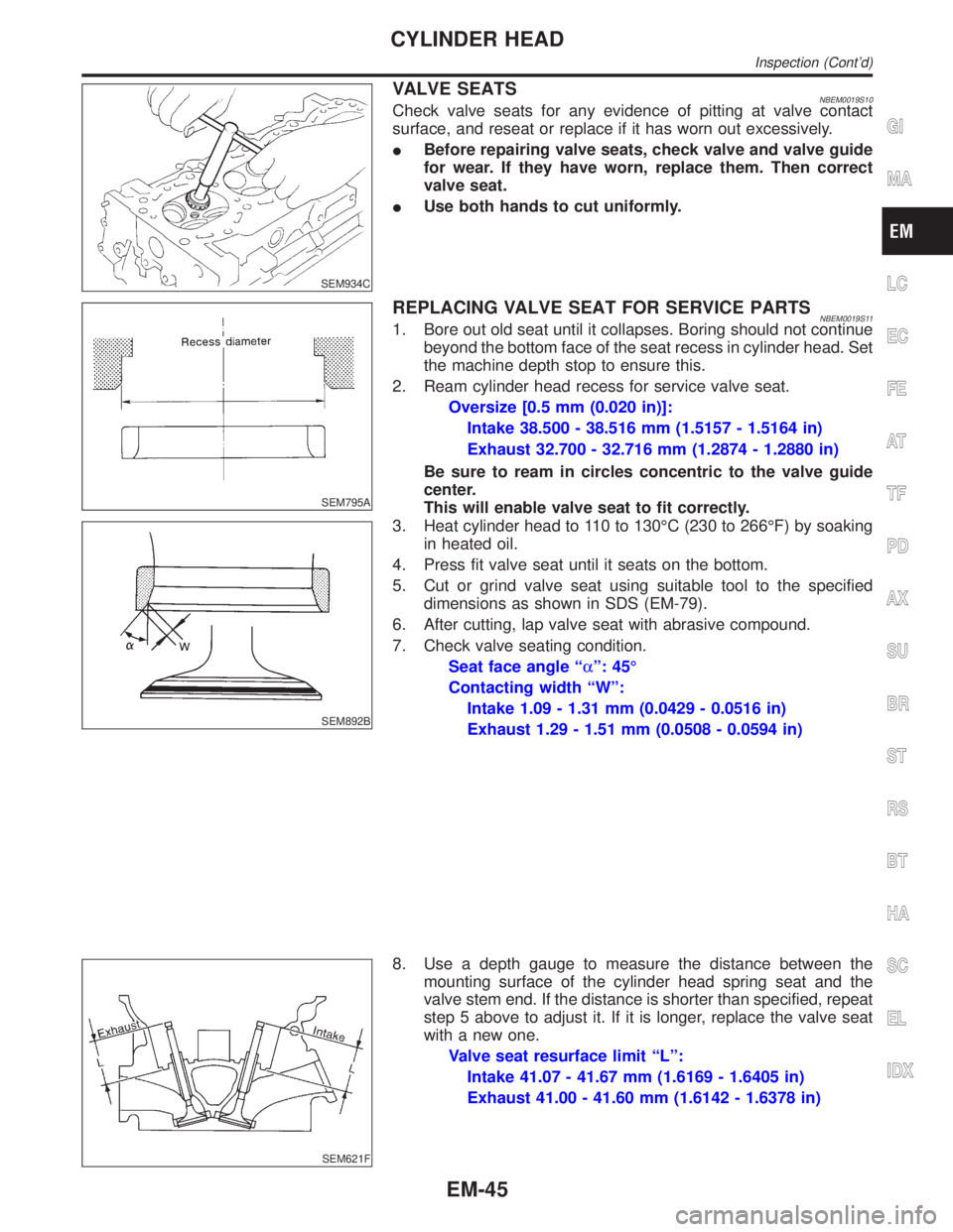
SEM934C
VALVE SEATSNBEM0019S10Check valve seats for any evidence of pitting at valve contact
surface, and reseat or replace if it has worn out excessively.
IBefore repairing valve seats, check valve and valve guide
for wear. If they have worn, replace them. Then correct
valve seat.
IUse both hands to cut uniformly.
SEM795A
REPLACING VALVE SEAT FOR SERVICE PARTSNBEM0019S111. Bore out old seat until it collapses. Boring should not continue
beyond the bottom face of the seat recess in cylinder head. Set
the machine depth stop to ensure this.
2. Ream cylinder head recess for service valve seat.
Oversize [0.5 mm (0.020 in)]:
Intake 38.500 - 38.516 mm (1.5157 - 1.5164 in)
Exhaust 32.700 - 32.716 mm (1.2874 - 1.2880 in)
Be sure to ream in circles concentric to the valve guide
center.
This will enable valve seat to fit correctly.
SEM892B
3. Heat cylinder head to 110 to 130ÉC (230 to 266ÉF) by soaking
in heated oil.
4. Press fit valve seat until it seats on the bottom.
5. Cut or grind valve seat using suitable tool to the specified
dimensions as shown in SDS (EM-79).
6. After cutting, lap valve seat with abrasive compound.
7. Check valve seating condition.
Seat face angle ªaº: 45É
Contacting width ªWº:
Intake 1.09 - 1.31 mm (0.0429 - 0.0516 in)
Exhaust 1.29 - 1.51 mm (0.0508 - 0.0594 in)
SEM621F
8. Use a depth gauge to measure the distance between the
mounting surface of the cylinder head spring seat and the
valve stem end. If the distance is shorter than specified, repeat
step 5 above to adjust it. If it is longer, replace the valve seat
with a new one.
Valve seat resurface limit ªLº:
Intake 41.07 - 41.67 mm (1.6169 - 1.6405 in)
Exhaust 41.00 - 41.60 mm (1.6142 - 1.6378 in)
GI
MA
LC
EC
FE
AT
TF
PD
AX
SU
BR
ST
RS
BT
HA
SC
EL
IDX
CYLINDER HEAD
Inspection (Cont'd)
EM-45
Page 1999 of 2395
NBMA0003
General maintenance includes those items which should be checked during the normal day-to-day operation
of the vehicle. They are essential if the vehicle is to continue operating properly. The owners can perform
checks and inspections themselves or they can have their INFINITI dealers do them.
OUTSIDE THE VEHICLE
The maintenance items listed here should be performed from time to time, unless otherwise specified.
ItemReference page
TiresCheck the pressure with a gauge periodically when at a service station,
including the spare, and adjust to the specified pressure if necessary. Check
carefully for damage, cuts or excessive wear.Ð
Wheel nutsWhen checking the tires, make sure no nuts are missing, and check for any
loose nuts. Tighten if necessary.Ð
Tire rotationTires should be rotated every 12,000 km (7,500 miles). MA-24
Wheel alignment and
balanceIf the vehicle pulls to either side while driving on a straight and level road, or
if you detect uneven or abnormal tire wear, there may be a need for wheel
alignment. If the steering wheel or seat vibrates at normal highway speeds,
wheel balancing may be needed.MA-24, SU-6, ªFront
Wheel Alignmentº
Windshield wiper
bladesCheck for cracks or wear if they do not wipe properly. Ð
Doors and engine
hoodCheck that all doors and the engine hood operate smoothly as well as the
trunk lid and back hatch. Also make sure that all latches lock securely. Lubri-
cate if necessary. Make sure that the secondary latch keeps the hood from
opening when the primary latch is released.
When driving in areas using road salt or other corrosive materials, check
lubrication frequently.MA-27
INSIDE THE VEHICLE
The maintenance items listed here should be checked on a regular basis, such as when performing periodic maintenance, cleaning the
vehicle, etc.
ItemReference page
LampsMake sure that the headlamps, stop lamps, tail lamps, turn signal lamps, and
other lamps are all operating properly and installed securely. Also check
headlamp aim.Ð
Warning lamps and
buzzers/chimesMake sure that all warning lamps and buzzers/chimes are operating properly. Ð
Windshield wiper
and washerCheck that the wipers and washer operate properly and that the wipers do
not streak.Ð
Windshield defrosterCheck that the air comes out of the defroster outlets properly and in sufficient
quantity when operating the heater or air conditioning.Ð
Steering wheelCheck that it has the specified play. Be sure to check for changes in the
steering condition, such as excessive play, hard steering or strange noises.
Free play: Less than 35 mm (1.38 in)Ð
SeatsCheck seat position controls such as seat adjusters, seatback recliner, etc. to
make sure they operate smoothly and that all latches lock securely in every
position. Check that the head restrains move up and down smoothly and that
the locks (if equipped) hold securely in all latched positions. Check that the
latches lock securely for folding-down rear seatbacks.Ð
Seat beltsCheck that all parts of the seat belt system (e.g. buckles, anchors, adjusters
and retractors) operate properly and smoothly and are installed securely.
Check the belt webbing for cuts, fraying, wear or damage.MA-28, RS-7, ªSeat Belt
Inspectionº
BrakesCheck that the brake does not pull the vehicle to one side when applied. Ð
GENERAL MAINTENANCE
MA-4
Page 2096 of 2395
Seat Belt Inspection=NBRS0029AFTER A COLLISIONNBRS0029S01WARNING:
Inspect all seat belt assemblies including retractors and attaching hardware after any collision.
NISSAN recommends that all seat belt assemblies in use during a collision be replaced unless the
collision was minor and the belts show no damage and continue to operate properly. Failure to do so
could result in serious personal injury in an accident. Seat belt assemblies not in use during a colli-
sion should also be replaced if either damage or improper operation is noted. Seat belt pre-tensioner
should be replaced even if the seat belts are not in use during a frontal collision in which the air bags
are deployed.
Replace any seat belt assembly if:
IThe seat belt was in use at the time of a collision (except for minor collisions and the belts, retractors and
buckles show no damage and continue to operate properly).
IThe seat belt was damaged in an accident. (i.e. torn webbing, bent retractor or guide, etc.)
IThe seat belt attaching point was damaged in an accident. Inspect the seat belt attaching area for dam-
age or distortion and repair as necessary before installing a new seat belt assembly.
IAnchor bolts are deformed or worn out.
IThe seat belt pre-tensioner should be replaced even if the seat belts are not in use during the collision in
which the air bags are deployed.
PRELIMINARY CHECKSNBRS0029S021. Check the seat belt warning lamp/chime for proper operation as follows:
a. Switch ignition ON. The seat belt warning lamp should illuminate. Also, the seat belt warning chime should
sound for about seven seconds.
b. Fasten driver's seat belt. The seat belt warning lamp should go out and the chime (if sounding) should
stop.
2. If the air bag warning lamp is blinking, conduct self-diagnosis using CONSULT-II, and air bag warning lamp.
Refer to ªSRS Operation Checkº, RS-38.
3. Check that the seat belt retractor, seat belt anchor and buckle bolts are securely attached.
4. Check the shoulder seat belt guide and shoulder belt height adjuster for front seats. Ensure guide swiv-
els freely and that belt lays flat and does not bind in guide. Ensure height adjuster operates properly and
holds securely.
5. Check retractor operation:
a. Fully extend the seat belt webbing and check for twists, tears or other damage.
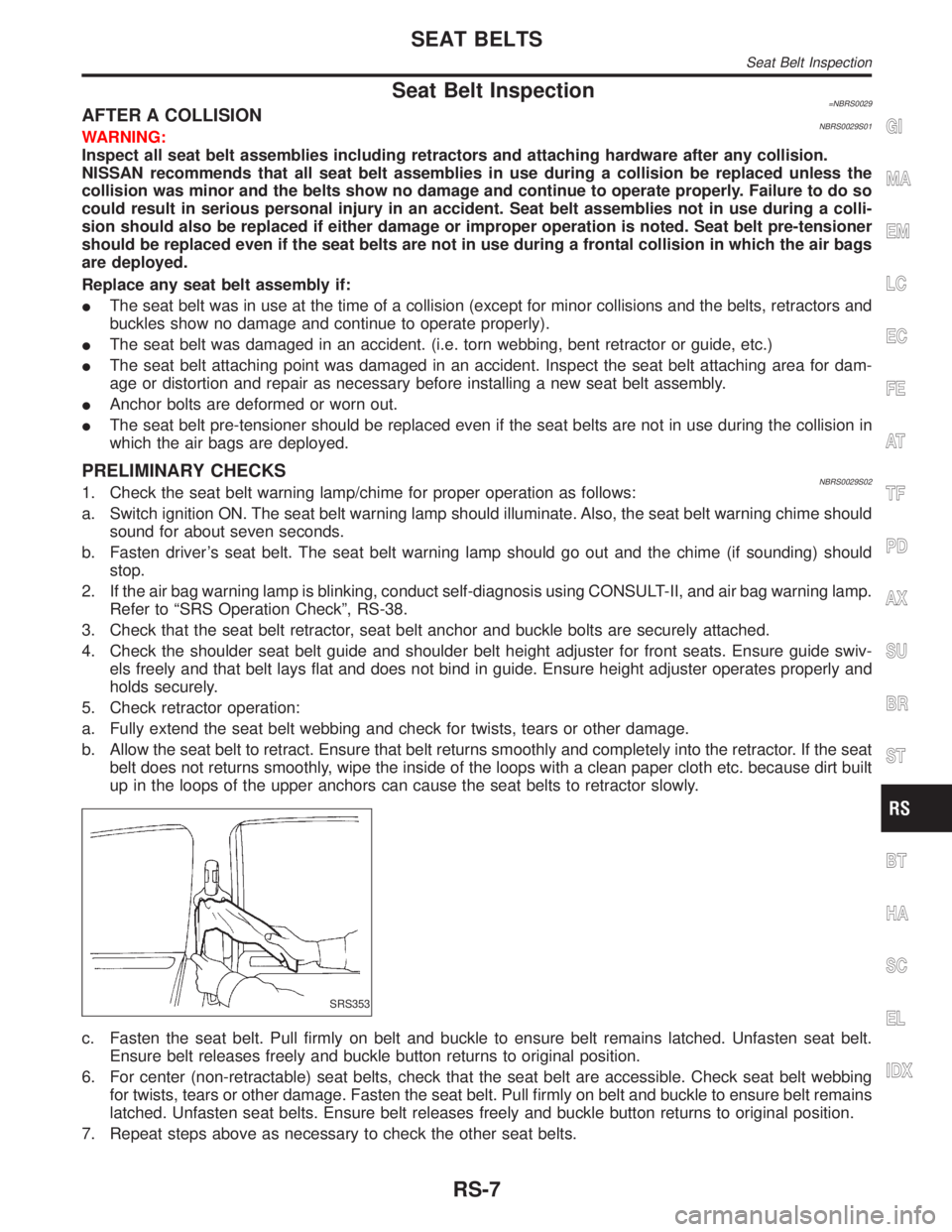
b. Allow the seat belt to retract. Ensure that belt returns smoothly and completely into the retractor. If the seat
belt does not returns smoothly, wipe the inside of the loops with a clean paper cloth etc. because dirt built
up in the loops of the upper anchors can cause the seat belts to retractor slowly.
SRS353
c. Fasten the seat belt. Pull firmly on belt and buckle to ensure belt remains latched. Unfasten seat belt.
Ensure belt releases freely and buckle button returns to original position.
6. For center (non-retractable) seat belts, check that the seat belt are accessible. Check seat belt webbing
for twists, tears or other damage. Fasten the seat belt. Pull firmly on belt and buckle to ensure belt remains
latched. Unfasten seat belts. Ensure belt releases freely and buckle button returns to original position.
7. Repeat steps above as necessary to check the other seat belts.
GI
MA
EM
LC
EC
FE
AT
TF
PD
AX
SU
BR
ST
BT
HA
SC
EL
IDX
SEAT BELTS
Seat Belt Inspection
RS-7