tires INFINITI QX4 2001 Factory Service Manual
[x] Cancel search | Manufacturer: INFINITI, Model Year: 2001, Model line: QX4, Model: INFINITI QX4 2001Pages: 2395, PDF Size: 43.2 MB
Page 153 of 2395

SAT342HA
DescriptionNBAT0051The torque converter clutch solenoid valve is activated, with the
gear in ªD
4º, by the TCM in response to signals sent from the
vehicle speed and throttle position sensors. Lock-up piston opera-
tion will then be controlled.
Lock-up operation, however, is prohibited when A/T fluid tempera-
ture is too low.
When the accelerator pedal is depressed (less than 2/8) in lock-up
condition, the engine speed should not change abruptly. If there is
a big jump in engine speed, there is no lock-up.
CONSULT-II REFERENCE VALUE IN DATA MONITOR
MODE
NBAT0051S02Remarks: Specification data are reference values.
Monitor item Condition Specification
Torque converter clutch
solenoid valve dutyLock-up ªOFFº
"
Lock-up ªONºApproximately 4%
"
Approximately 94%
TCM TERMINALS AND REFERENCE VALUENBAT0051S03Remarks: Specification data are reference values.
Terminal
No.Wire color Item ConditionJudgement
standard
(Approx.)
3 G/ORTorque converter
clutch solenoid
valve
When A/T performs lock-up. 8 - 15V
When A/T does not perform lock-up. 0V
ON BOARD DIAGNOSIS LOGICNBAT0051S04
Diagnostic trouble code Malfunction is detected when ... Check item (Possible cause)
: TCC SOLENOID/CIRC TCM detects an improper voltage drop
when it tires to operate the solenoid
valve.IHarness or connectors
(The solenoid circuit is open or shorted.)
ITorque converter clutch solenoid valve
: P0740
DTC P0740 TORQUE CONVERTER CLUTCH SOLENOID VALVE
Description
AT-148
Page 173 of 2395

SAT341H
DescriptionNBAT0060Shift solenoid valves A and B are turned ªONº or ªOFFº by the TCM
in response to signals sent from the PNP switch, vehicle speed and
throttle position sensors. Gears will then be shifted to the optimum
position.
Gear position1234
Shift solenoid valve A ON (Closed) OFF (Open) OFF (Open) ON (Closed)
Shift solenoid valve B ON (Closed) ON (Closed) OFF (Open) OFF (Open)
TCM TERMINALS AND REFERENCE VALUENBAT0060S02Remarks: Specification data are reference values.
Terminal
No.Wire color Item ConditionJudgement
standard
(Approx.)
11 L/WShift solenoid
valve A
When shift solenoid valve A operates.
(When driving in ªD
1ºorªD4º.)Battery volt-
age
When shift solenoid valve A does not operate.
(When driving in ªD
2ºorªD3º.)0V
ON BOARD DIAGNOSIS LOGICNBAT0060S03
Diagnostic trouble code Malfunction is detected when ... Check item (Possible cause)
: SFT SOL A/CIRC TCM detects an improper voltage drop
when it tires to operate the solenoid
valve.IHarness or connectors
(The solenoid circuit is open or shorted.)
IShift solenoid valve A
: P0750
SAT014K
SAT020K
DIAGNOSTIC TROUBLE CODE (DTC) CONFIRMATION
PROCEDURE
NBAT0060S01CAUTION:
Always drive vehicle at a safe speed.
NOTE:
If ªDIAGNOSTIC TROUBLE CODE CONFIRMATION PROCE-
DUREº has been previously conducted, always turn ignition
switch ªOFFº and wait at least 5 seconds before conducting
the next test.
After the repair, perform the following procedure to confirm the
malfunction is eliminated.
With CONSULT-II
1) Turn ignition switch ªONº and select ªDATA MONITORº mode
for ªENGINEº with CONSULT-II.
2) Start engine.
3) Drive vehicle in ªDº position and allow the transmission to shift
ª1º,ª2º (ªGEARº).
With GST
Follow the procedure ªWith CONSULT-IIº.
DTC P0750 SHIFT SOLENOID VALVE A
Description
AT-168
Page 177 of 2395

SAT341H
DescriptionNBAT0063Shift solenoid valves A and B are turned ªONº or ªOFFº by the TCM
in response to signals sent from the PNP switch, vehicle speed and
throttle position sensors. Gears will then be shifted to the optimum
position.
Gear position1234
Shift solenoid valve A ON (Closed) OFF (Open) OFF (Open) ON (Closed)
Shift solenoid valve B ON (Closed) ON (Closed) OFF (Open) OFF (Open)
TCM TERMINALS AND REFERENCE VALUENBAT0063S02Remarks: Specification data are reference values.
Terminal
No.Wire color Item ConditionJudgement
standard
(Approx.)
12 L/RShift solenoid
valve B
When shift solenoid valve B operates.
(When driving in ªD
1ºorªD2º.)Battery volt-
age
When shift solenoid valve B does not operate.
(When driving in ªD
3ºorªD4º.)0V
ON BOARD DIAGNOSIS LOGICNBAT0063S03
Diagnostic trouble code Malfunction is detected when ... Check item (Possible cause)
: SFT SOL B/CIRC TCM detects an improper voltage drop
when it tires to operate the solenoid
valve.IHarness or connectors
(The solenoid circuit is open or shorted.)
IShift solenoid valve B
: P0755
SAT014K
SAT020K
DIAGNOSTIC TROUBLE CODE (DTC) CONFIRMATION
PROCEDURE
NBAT0063S01CAUTION:
Always drive vehicle at a safe speed.
NOTE:
If ªDIAGNOSTIC TROUBLE CODE CONFIRMATION PROCE-
DUREº has been previously conducted, always turn ignition
switch ªOFFº and wait at least 5 seconds before conducting
the next test.
After the repair, perform the following procedure to confirm the
malfunction is eliminated.
With CONSULT-II
1) Turn ignition switch ªONº and select ªDATA MONITORº mode
for ªENGINEº with CONSULT-II.
2) Drive vehicle in ªDº position and allow the transmission to shift
1,2,3 (ªGEARº).
With GST
Follow the procedure ªWith CONSULT-IIº.
DTC P0755 SHIFT SOLENOID VALVE B
Description
AT-172
Page 369 of 2395

SBR686C
Precautions
PRECAUTIONSNBAX0001IWhen installing rubber parts, final tightening must be car-
ried out under unladen condition* with tires on ground.
*Fuel, radiator coolant and engine oil full. Spare tire, jack,
hand tools and mats in designated positions.
IUse flare nut wrench when removing and installing brake
tubes.
IAfter installing removed suspension parts, check wheel
alignment and adjust if necessary.
IAlways torque brake lines when installing.
Preparation
SPECIAL SERVICE TOOLSNBAX0002The actual shapes of Kent-Moore tools may differ from those of special service tools illustrated here.
Tool number
(Kent-Moore No.)
Tool nameDescription
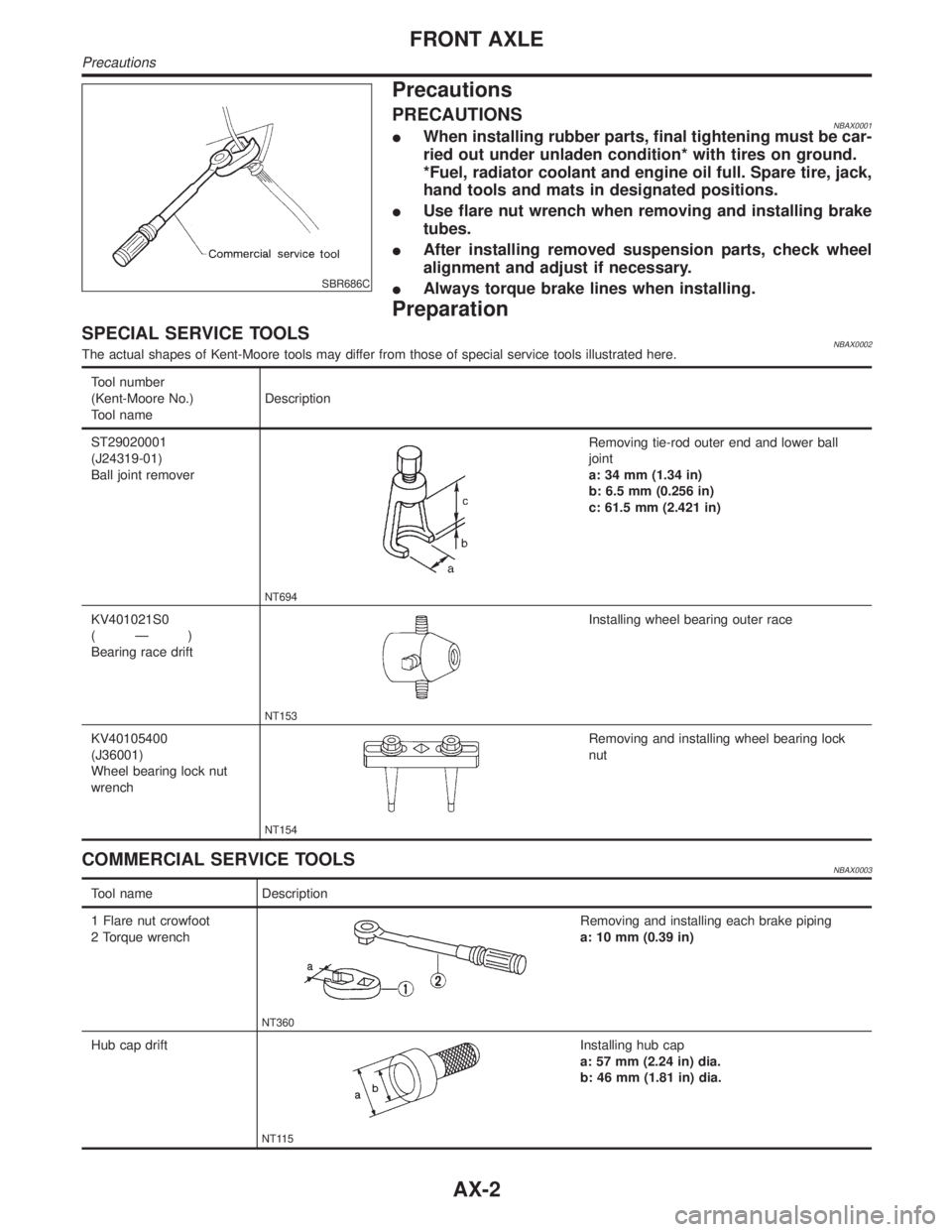
ST29020001
(J24319-01)
Ball joint remover
NT694
Removing tie-rod outer end and lower ball
joint
a: 34 mm (1.34 in)
b: 6.5 mm (0.256 in)
c: 61.5 mm (2.421 in)
KV401021S0
(Ð)
Bearing race drift
NT153
Installing wheel bearing outer race
KV40105400
(J36001)
Wheel bearing lock nut
wrench
NT154
Removing and installing wheel bearing lock
nut
COMMERCIAL SERVICE TOOLSNBAX0003
Tool name Description
1 Flare nut crowfoot
2 Torque wrench
NT360
Removing and installing each brake piping
a: 10 mm (0.39 in)
Hub cap drift
NT115
Installing hub cap
a: 57 mm (2.24 in) dia.
b: 46 mm (1.81 in) dia.
FRONT AXLE
Precautions
AX-2
Page 370 of 2395

Noise, Vibration and Harshness (NVH)
Troubleshooting
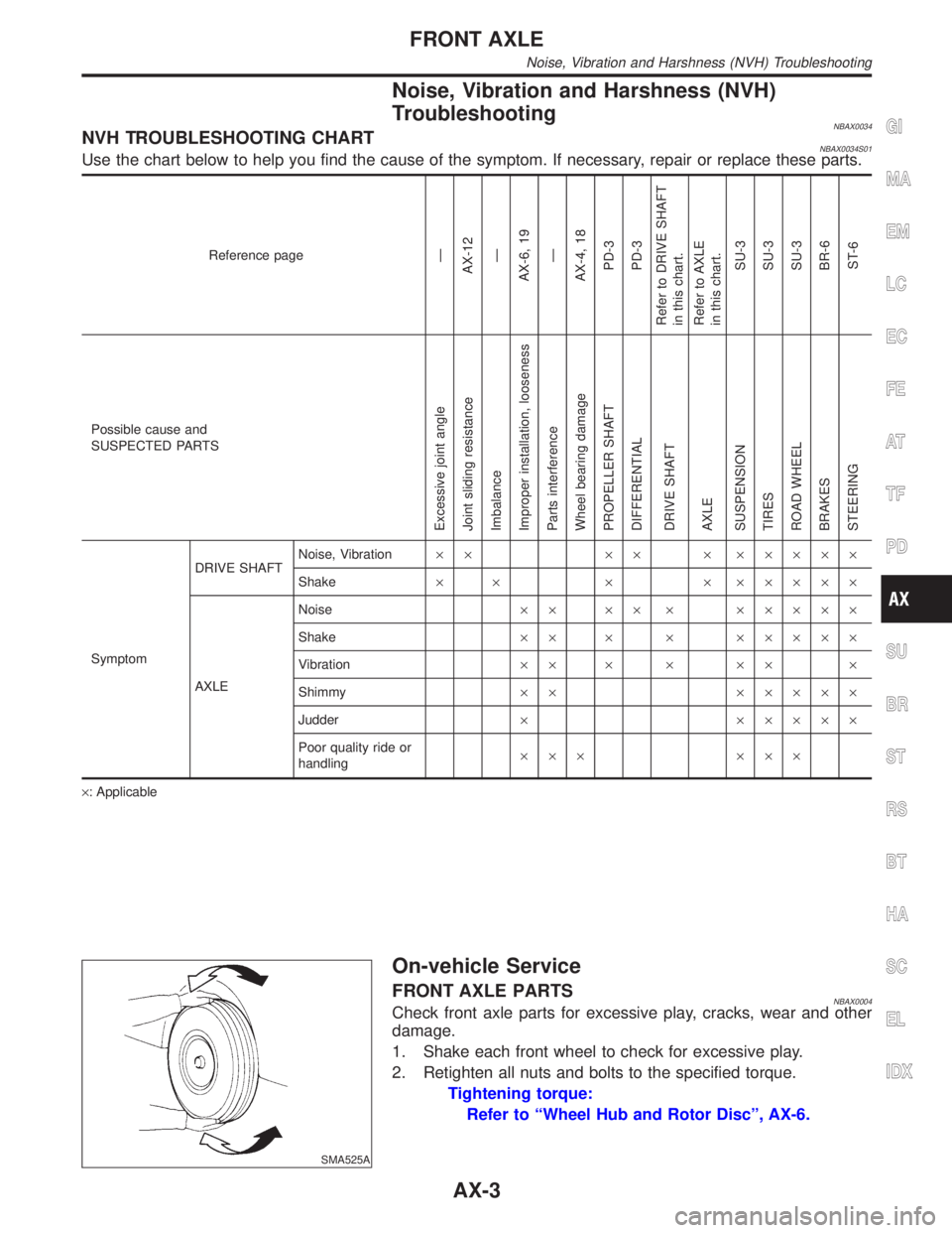
NBAX0034NVH TROUBLESHOOTING CHARTNBAX0034S01Use the chart below to help you find the cause of the symptom. If necessary, repair or replace these parts.
Reference pageÐ
AX-12
Ð
AX-6, 19
Ð
AX-4, 18
PD-3
PD-3
Refer to DRIVE SHAFT
in this chart.
Refer to AXLE
in this chart.
SU-3
SU-3
SU-3
BR-6
ST-6
Possible cause and
SUSPECTED PARTS
Excessive joint angle
Joint sliding resistance
Imbalance
Improper installation, looseness
Parts interference
Wheel bearing damage
PROPELLER SHAFT
DIFFERENTIAL
DRIVE SHAFT
AXLE
SUSPENSION
TIRES
ROAD WHEEL
BRAKES
STEERING
SymptomDRIVE SHAFTNoise, Vibration´´ ´´ ´ ´´´´´
Shake´ ´ ´ ´ ´´´´´
AXLENoise´´ ´´ ´ ´´´´´
Shake´´ ´ ´ ´´´´´
Vibration´´ ´ ´ ´´ ´
Shimmy´´ ´´´´´
Judder´ ´´´´´
Poor quality ride or
handling´´´ ´´´
´: Applicable
SMA525A
On-vehicle Service
FRONT AXLE PARTSNBAX0004Check front axle parts for excessive play, cracks, wear and other
damage.
1. Shake each front wheel to check for excessive play.
2. Retighten all nuts and bolts to the specified torque.
Tightening torque:
Refer to ªWheel Hub and Rotor Discº, AX-6.
GI
MA
EM
LC
EC
FE
AT
TF
PD
SU
BR
ST
RS
BT
HA
SC
EL
IDX
FRONT AXLE
Noise, Vibration and Harshness (NVH) Troubleshooting
AX-3
Page 384 of 2395

SBR686C
Precautions
PRECAUTIONSNBAX0023IWhen installing rubber parts, final tightening must be car-
ried out under unladen condition* with tires on ground.
*Fuel, radiator coolant and engine oil full. Spare tire, jack,
hand tools and mats in designated positions.
IUse flare nut wrench when removing and installing brake
tubes.
IAfter installing removed suspension parts, check wheel
alignment and adjust if necessary.
IAlways torque brake lines when installing.
Preparation
SPECIAL SERVICE TOOLSNBAX0024The actual shapes of Kent-Moore tools may differ from those of special service tools illustrated here.
Tool number
(Kent-Moore No.)
Tool nameDescription
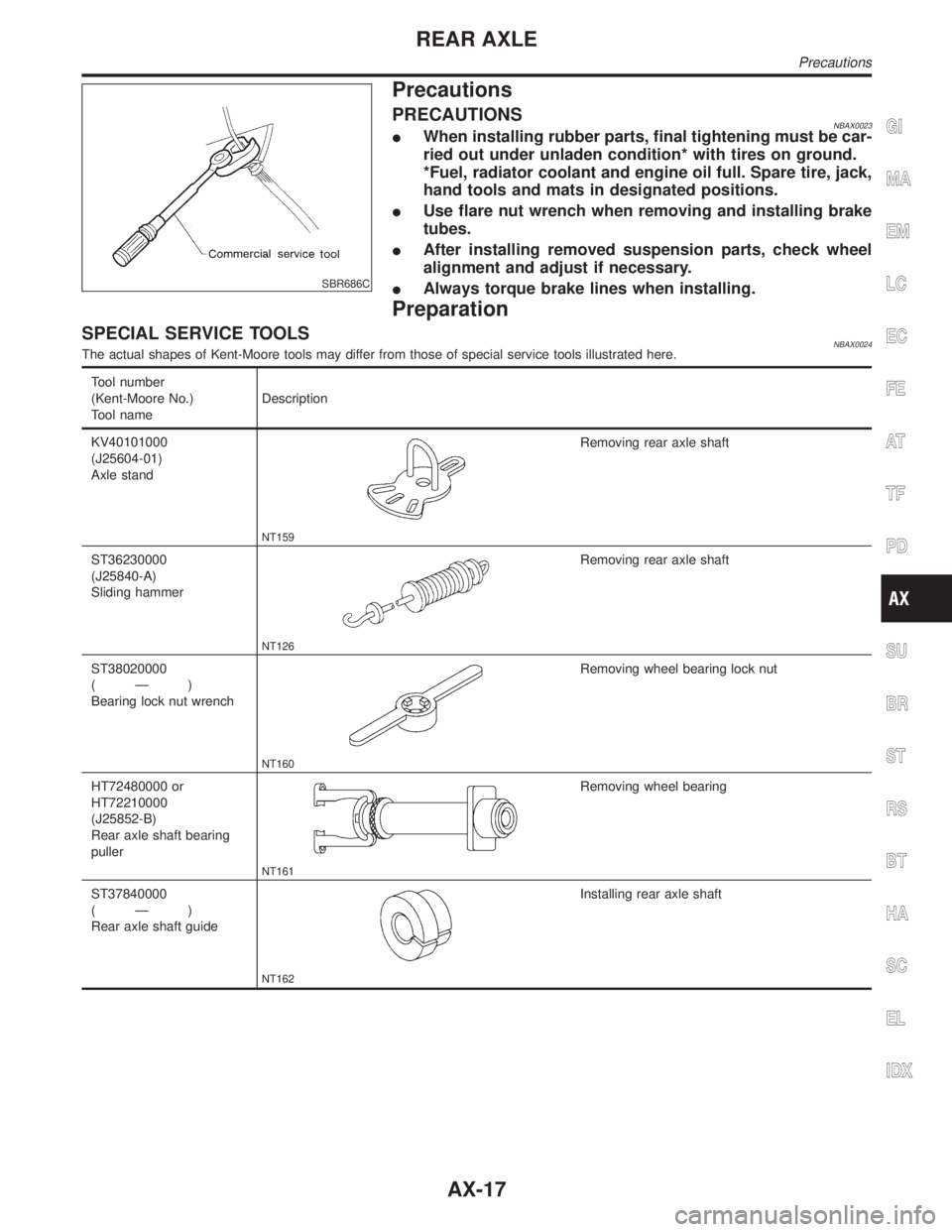
KV40101000
(J25604-01)
Axle stand
NT159
Removing rear axle shaft
ST36230000
(J25840-A)
Sliding hammer
NT126
Removing rear axle shaft
ST38020000
(Ð)
Bearing lock nut wrench
NT160
Removing wheel bearing lock nut
HT72480000 or
HT72210000
(J25852-B)
Rear axle shaft bearing
puller
NT161
Removing wheel bearing
ST37840000
(Ð)
Rear axle shaft guide
NT162
Installing rear axle shaft
GI
MA
EM
LC
EC
FE
AT
TF
PD
SU
BR
ST
RS
BT
HA
SC
EL
IDX
REAR AXLE
Precautions
AX-17
Page 395 of 2395

NBBR0085
NVH Troubleshooting ChartNBBR0085S01Use the chart below to help you find the cause of the symptom. If necessary, repair or replace these parts.
Reference page
BR-22, 28
BR-22, 28
BR-26
BR-22
Ð
Ð
BR-24, 28
Ð
Ð
Ð
BR-25
BR-28
PD-3
PD-3
AX-3
AX-3
SU-3
SU-3
SU-3
ST-6
Possible cause and
SUSPECTED PARTS
Linings or pads - damaged
Linings or pads - uneven wear
Return spring damaged
Shims damaged
Rotor or drum imbalance
Rotor or drum damage
Rotor or drum runout
Rotor or drum deformation
Rotor or drum deflection
Rotor or drum rust
Rotor thickness variation
Drum out of round
PROPELLER SHAFT
DIFFERENTIAL
DRIVE SHAFT
AXLE
SUSPENSION
TIRES
ROAD WHEEL
STEERING
Symptom BRAKENoise´´´´ ´´´´´´´´
Shake´ ´ ´´´´´´
Shimmy, Judder´´´´´´´´ ´´´´´
´: Applicable
NOISE, VIBRATION AND HARSHNESS (NVH) TROUBLESHOOTING
NVH Troubleshooting Chart
BR-6
Page 1259 of 2395

SEL350X
Aiming AdjustmentNBEL0029Before performing aiming adjustment, make sure of the following.
1) Keep all tires inflated to correct pressure.
2) Place vehicle on level ground.
3) See that vehicle is unloaded (except for full levels of coolant,
engine oil and fuel, and spare tire, jack, and tools). Have the
driver or equivalent weight placed in driver's seat.
Adjust aiming in the vertical direction by turning the adjusting
screw.
MEL327G
1. Set the distance between the screen and the center of the fog
lamp lens as shown at left.
2. Turn front fog lamps ON.
MEL328GA
3. Adjust front fog lamps so that the top edge of the high inten-
sity zone is 200 mm (7.9 in) below the height of the fog lamp
centers as shown at left.
IWhen performing adjustment, if necessary, cover the head-
lamps and opposite fog lamp.
FRONT FOG LAMP
Aiming Adjustment
EL-74
Page 1747 of 2395

Wheels & Tires ..........................................................44
LIFTING POINTS AND TOW TRUCK TOWING...........45
Screw Jack ................................................................45
Garage Jack and Safety Stand .................................46
2-pole Lift ...................................................................47
Tow Truck Towing ......................................................472WD MODELS.........................................................48
4WD MODELS.........................................................48
VEHICLE RECOVERY..............................................49
TIGHTENING TORQUE OF STANDARD BOLTS........50
SAE J1930 TERMINOLOGY LIST................................51
SAE J1930 Terminology List .....................................51
CONTENTS(Cont'd)
GI-2
Page 1789 of 2395

Wheels & TiresNBGI0007S04
Grade Road wheel/offset mm (in) Tire Spare tire size
LE17 x 8JJ Aluminum/20 (0.79)
16 x 7JJ Aluminum/20 (0.79)*P245/65R17 105S
P245/70R16 106S*P245/65R17 105S
* Option for 2WD model
IDENTIFICATION INFORMATION
Wheels & Tires
GI-44