steering INFINITI QX4 2001 Factory Service Manual
[x] Cancel search | Manufacturer: INFINITI, Model Year: 2001, Model line: QX4, Model: INFINITI QX4 2001Pages: 2395, PDF Size: 43.2 MB
Page 2205 of 2395

SST609C
14. Ensure that the rack is centered. Install rear cover cap so that
its protrusion is positioned as shown in figure.
Be careful not to damage worm ring and oil seal.
15. Install retainer, spring and adjusting screw temporarily.
SST135C
16. Install new lock plate.
IAttach lock plate 2 to side rod inner socket 1.
IApply locking sealant to inner socket threads 3.
Screw inner socket into rack 4 and tighten to specified torque.
IClinch two places of lock plate at rack's groove.
CAUTION:
To prevent scratching the boot, remove burrs from lock plate.
SST655C
17. Tighten outer socket lock nut.
Tie-rod length ªLº:
Refer to SDS, ST-33.
18. Measure rack stroke.
Rack stroke ªSº:
Refer to SDS, ST-33.
SST967A
19. Before installing boot, coat the contact surfaces between boot
and tie-rod with grease.
SST619C
AdjustmentNBST0031Adjust pinion rotating torque as follows:
1. Set rack to the neutral position without fluid in the gear.
2. Coat the adjusting screw with locking sealant and screw it in.
3. Lightly tighten lock nut.
4. Tighten adjusting screw to a torque of 4.9 to 5.9 N´m (50 to 60
kg-cm, 43 to 52 in-lb).
5. Loosen adjusting screw, then retighten it to 0.2 N´m (2 kg-cm,
1.7 in-lb).
POWER STEERING GEAR AND LINKAGE
Assembly (Cont'd)
ST-24
Page 2206 of 2395
SST718CA
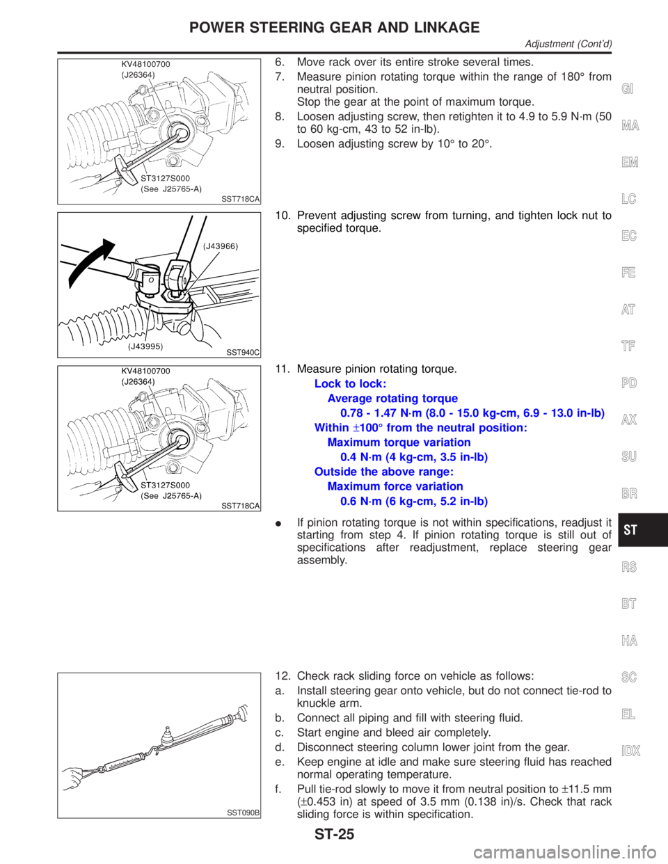
6. Move rack over its entire stroke several times.
7. Measure pinion rotating torque within the range of 180É from
neutral position.
Stop the gear at the point of maximum torque.
8. Loosen adjusting screw, then retighten it to 4.9 to 5.9 N´m (50
to 60 kg-cm, 43 to 52 in-lb).
9. Loosen adjusting screw by 10É to 20É.
SST940C
10. Prevent adjusting screw from turning, and tighten lock nut to
specified torque.
SST718CA
11. Measure pinion rotating torque.
Lock to lock:
Average rotating torque
0.78 - 1.47 N´m (8.0 - 15.0 kg-cm, 6.9 - 13.0 in-lb)
Within±100É from the neutral position:
Maximum torque variation
0.4 N´m (4 kg-cm, 3.5 in-lb)
Outside the above range:
Maximum force variation
0.6 N´m (6 kg-cm, 5.2 in-lb)
IIf pinion rotating torque is not within specifications, readjust it
starting from step 4. If pinion rotating torque is still out of
specifications after readjustment, replace steering gear
assembly.
SST090B
12. Check rack sliding force on vehicle as follows:
a. Install steering gear onto vehicle, but do not connect tie-rod to
knuckle arm.
b. Connect all piping and fill with steering fluid.
c. Start engine and bleed air completely.
d. Disconnect steering column lower joint from the gear.
e. Keep engine at idle and make sure steering fluid has reached
normal operating temperature.
f. Pull tie-rod slowly to move it from neutral position to±11.5 mm
(±0.453 in) at speed of 3.5 mm (0.138 in)/s. Check that rack
sliding force is within specification.
GI
MA
EM
LC
EC
FE
AT
TF
PD
AX
SU
BR
RS
BT
HA
SC
EL
IDX
POWER STEERING GEAR AND LINKAGE
Adjustment (Cont'd)
ST-25
Page 2207 of 2395
Rack sliding force:
167 - 254 N (17.0 - 25.9 kg, 37 - 57 lb)
IIf rack sliding force is not within specification, readjust by
repeating adjustment procedure from the beginning.
IIf rack sliding force is still out of specification after
readjustment, gear assembly needs to be replaced.
POWER STEERING GEAR AND LINKAGE
Adjustment (Cont'd)
ST-26
Page 2208 of 2395
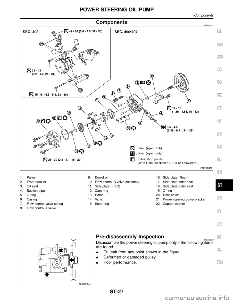
ComponentsNBST0032
SST924C
1. Pulley
2. Front bracket
3. Oil seal
4. Suction pipe
5. O-ring
6. Casing
7. Flow control valve spring
8. Flow control A valve9. Dowel pin
10. Flow control B valve assembly
11. Side plate (Front)
12. Cam ring
13. Rotor
14. Vane
15. Snap ring16. Side plate (Rear)
17. Side plate inner seal
18. Side plate outer seal
19. O-ring
20. Rear cover
21. Power steering pump bracket
22. Copper washer
SST925C
Pre-disassembly InspectionNBST0033Disassemble the power steering oil pump only if the following items
are found.
IOil leak from any point shown in the figure.
IDeformed or damaged pulley.
IPoor performance.
GI
MA
EM
LC
EC
FE
AT
TF
PD
AX
SU
BR
RS
BT
HA
SC
EL
IDX
POWER STEERING OIL PUMP
Components
ST-27
Page 2209 of 2395

DisassemblyNBST0034CAUTION:
IParts which can be disassembled are strictly limited.
Never disassemble parts other than those specified.
IDisassemble in as clean a place as possible.
IClean your hands before disassembly.
IDo not use rags; use nylon cloths or paper towels.
IFollow the procedures and cautions in the Service
Manual.
IWhen disassembling and reassembling, do not let foreign
matter enter or contact the parts.
1. Fix power steering pump to vise.
CAUTION:
When fixing the pump to vise, use an aluminum plate or such
to avoid damaging the fitting plane of the steering pump.
2. Remove the front bracket mounting bolt, and remove the front
bracket from the casing.
3. Remove the rear cover mounting bolt, and remove the rear
cover from the casing.
4. Remove the O-ring from the casing.
SST926C
5. Remove side plate (rear side) from cam ring, then remove side
plate inner/outer seals from side plate (rear side).
6. Remove rotor snap ring using snap ring pliers, and remove
pulley from casing.
CAUTION:
Do not damage pulley shaft when removing rotor snap ring.
SST928C
7. Remove the followings from casing.
ICam ring
IRotor
IVane
ISide plate (front side)
IFlow control A valve
IFlow control valve spring
IFlow control B valve assembly
CAUTION:
Be careful not to drop flow control valve.
8. Remove inlet connector mounting bolt, and remove inlet con-
nector from casing.
9. Remove inlet connector seal from inlet connector.
10. Remove drive shaft seal from casing with a screwdriver.
CAUTION:
Do not damage casing surface with the screwdriver.
POWER STEERING OIL PUMP
Disassembly
ST-28
Page 2210 of 2395
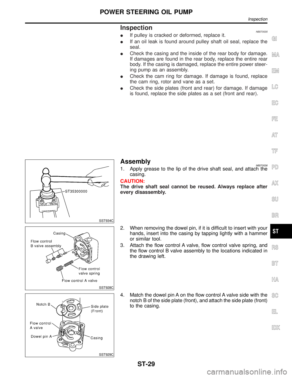
InspectionNBST0035IIf pulley is cracked or deformed, replace it.
IIf an oil leak is found around pulley shaft oil seal, replace the
seal.
ICheck the casing and the inside of the rear body for damage.
If damages are found in the rear body, replace the entire rear
body. If the casing is damaged, replace the entire power steer-
ing pump as an assembly.
ICheck the cam ring for damage. If damage is found, replace
the cam ring, rotor and vane as a set.
ICheck the side plates (front and rear) for damage. If damage
is found, replace the side plates as a set (front and rear).
SST934C
AssemblyNBST00361. Apply grease to the lip of the drive shaft seal, and attach the
casing.
CAUTION:
The drive shaft seal cannot be reused. Always replace after
every disassembly.
SST928C
2. When removing the dowel pin, if it is difficult to insert with your
hands, insert into the casing by tapping lightly with a hammer
or similar tool.
3. Attach the flow control A valve, flow control valve spring, and
the flow control B valve assembly to the locations indicated in
the drawing left.
SST929C
4. Match the dowel pin A on the flow control A valve side with the
notch B of the side plate (front), and attach the side plate (front)
to the casing.
GI
MA
EM
LC
EC
FE
AT
TF
PD
AX
SU
BR
RS
BT
HA
SC
EL
IDX
POWER STEERING OIL PUMP
Inspection
ST-29
Page 2211 of 2395

SST930C
5. Face the cam ring side with fewer pores towards the casing,
and attach the cam ring on top of the side plate (front).
6. Attach the pulley to the casing.
CAUTION:
Attach with care so as not to damage the drive shaft seal.
SST289A
7. Face the side of the rotor with the punch mark towards the
casing, and attach the rotor to the pulley shaft.
SST843A
8. Attach the vane to the rotor so that the vane's arc touches the
cam ring.
SST931C
9. Use a hammer or suitable tool to insert the rotor snap ring into
the pulley shaft channel.
CAUTION:
IThe rotor snap ring cannot be reused. Always replace after
every disassembly.
IInsert with care so as not to damage the rotor or the pul-
ley shaft.
IIf the rotor is damaged, replace the power steering as an
assembly.
SST932C
10. Match the dowel pin A on the flow control A valve side with the
notch B of the side plate (rear), and attach the side plate (rear)
to the cam ring.
11. Apply Genuine Nissan PSF II or equivalent to O-ring and
attach to the casing.
CAUTION:
The O-ring cannot be reused. Always replace after every dis-
assembly.
POWER STEERING OIL PUMP
Assembly (Cont'd)
ST-30
Page 2212 of 2395
SST933C
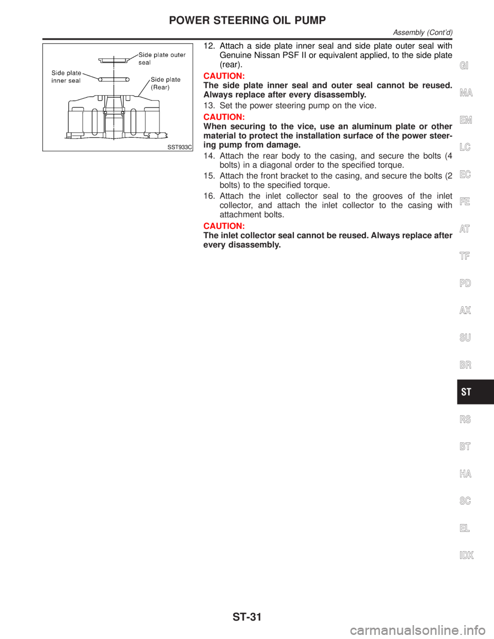
12. Attach a side plate inner seal and side plate outer seal with
Genuine Nissan PSF II or equivalent applied, to the side plate
(rear).
CAUTION:
The side plate inner seal and outer seal cannot be reused.
Always replace after every disassembly.
13. Set the power steering pump on the vice.
CAUTION:
When securing to the vice, use an aluminum plate or other
material to protect the installation surface of the power steer-
ing pump from damage.
14. Attach the rear body to the casing, and secure the bolts (4
bolts) in a diagonal order to the specified torque.
15. Attach the front bracket to the casing, and secure the bolts (2
bolts) to the specified torque.
16. Attach the inlet collector seal to the grooves of the inlet
collector, and attach the inlet collector to the casing with
attachment bolts.
CAUTION:
The inlet collector seal cannot be reused. Always replace after
every disassembly.
GI
MA
EM
LC
EC
FE
AT
TF
PD
AX
SU
BR
RS
BT
HA
SC
EL
IDX
POWER STEERING OIL PUMP
Assembly (Cont'd)
ST-31
Page 2213 of 2395

General SpecificationsNBST0037
Applied modelAll
Steering modelPower steering
Steering gear typePR32K
Steering overall gear ratio 17.2
Turns of steering wheel
(Lock to lock)3.09
Steering column type Collapsible, tilt
Steering WheelNBST0038Unit: mm (in)
Steering wheel axial play0 (0)
Steering wheel play35 (1.38) or less
Movement of gear housing±2(±0.08) or less
Steering ColumnNBST0039Unit: mm (in)
Steering column length ªL1º 716.7 - 718.7 (28.22 - 28.30)
Steering column lower shaft length ªL
2º 178 - 180 (7.01 - 7.09)
Steering column upper joint length ªL
3º 430.7 - 432.7 (16.96 - 17.04)
SST739C
Steering Transfer GearNBST0041
Rotating torque0.25 - 0.69 N´m (2.5 - 7.0 kg-cm, 2.2 - 6.1 in-lb)
SERVICE DATA AND SPECIFICATIONS (SDS)
General Specifications
ST-32
Page 2214 of 2395
Steering Gear and LinkageNBST0040
Applied modelAll
Steering gear typePR32K
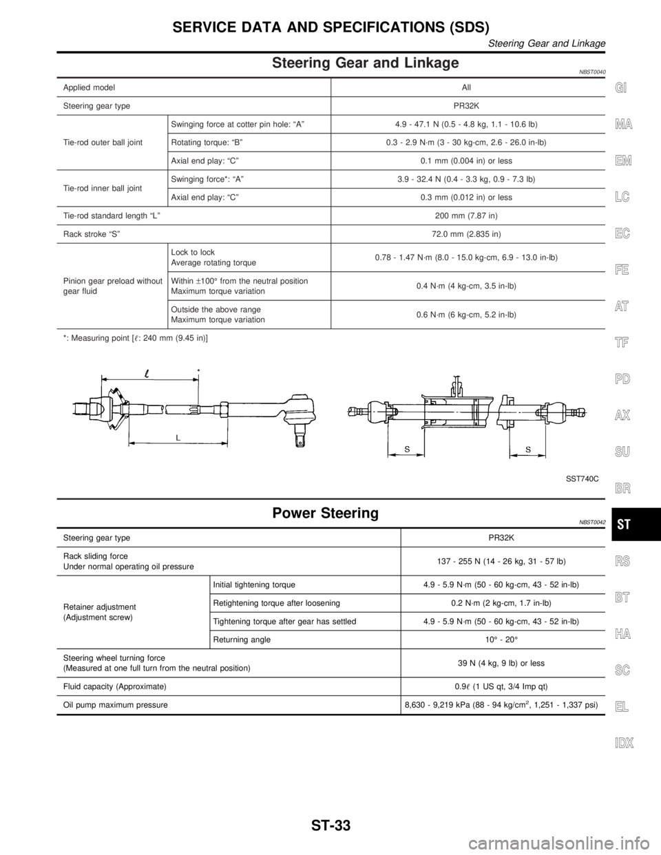
Tie-rod outer ball jointSwinging force at cotter pin hole: ªAº 4.9 - 47.1 N (0.5 - 4.8 kg, 1.1 - 10.6 lb)
Rotating torque: ªBº 0.3 - 2.9 N´m (3 - 30 kg-cm, 2.6 - 26.0 in-lb)
Axial end play: ªCº 0.1 mm (0.004 in) or less
Tie-rod inner ball jointSwinging force*: ªAº 3.9 - 32.4 N (0.4 - 3.3 kg, 0.9 - 7.3 lb)
Axial end play: ªCº 0.3 mm (0.012 in) or less
Tie-rod standard length ªLº200 mm (7.87 in)
Rack stroke ªSº72.0 mm (2.835 in)
Pinion gear preload without
gear fluidLock to lock
Average rotating torque0.78 - 1.47 N´m (8.0 - 15.0 kg-cm, 6.9 - 13.0 in-lb)
Within±100É from the neutral position
Maximum torque variation0.4 N´m (4 kg-cm, 3.5 in-lb)
Outside the above range
Maximum torque variation0.6 N´m (6 kg-cm, 5.2 in-lb)
*: Measuring point [: 240 mm (9.45 in)]
SST740C
Power SteeringNBST0042
Steering gear typePR32K
Rack sliding force
Under normal operating oil pressure137 - 255 N (14 - 26 kg, 31 - 57 lb)
Retainer adjustment
(Adjustment screw)Initial tightening torque 4.9 - 5.9 N´m (50 - 60 kg-cm, 43 - 52 in-lb)
Retightening torque after loosening 0.2 N´m (2 kg-cm, 1.7 in-lb)
Tightening torque after gear has settled 4.9 - 5.9 N´m (50 - 60 kg-cm, 43 - 52 in-lb)
Returning angle 10É - 20É
Steering wheel turning force
(Measured at one full turn from the neutral position)39 N (4 kg, 9 lb) or less
Fluid capacity (Approximate)0.9(1 US qt, 3/4 Imp qt)
Oil pump maximum pressure 8,630 - 9,219 kPa (88 - 94 kg/cm
2, 1,251 - 1,337 psi)
GI
MA
EM
LC
EC
FE
AT
TF
PD
AX
SU
BR
RS
BT
HA
SC
EL
IDX
SERVICE DATA AND SPECIFICATIONS (SDS)
Steering Gear and Linkage
ST-33