load capacity INFINITI QX4 2001 Factory Service Manual
[x] Cancel search | Manufacturer: INFINITI, Model Year: 2001, Model line: QX4, Model: INFINITI QX4 2001Pages: 2395, PDF Size: 43.2 MB
Page 1965 of 2395

LSV (Load sensing valve) ..............................BR-12
Lubricant (R134a) A/C..................................HA-146
Lubricants .......................................................MA-11
Lubrication circuit (engine) ...............................LC-3
Lubrication-locks, hinges and hood
latches ........................................................MA-27
Luggage room lamp ........................................EL-88
M
MAFS - Wiring diagram................................EC-154
Magnet clutch .......................................HA-104, 150
MAIN - Wiring diagram.................................EC-142
Main oil pump (Transfer)...............................TF-131
Mainshaft (Transfer) ......................................TF-125
Maintenance (engine) ....................................MA-13
MAJOR OVERHALL......................................AT-281
Major overhaul (Transfer) .............................TF-120
Malfunction indicator lamp (MIL) ....................EC-74
Mass air flow sensor (MAFS) .......................EC-150
Master cylinder (brake) ..................................BR-16
Meter ...............................................................EL-94
METER - Wiring diagram................................EL-99
MIL & Data link connectors circuit ...............EC-648
MIL/DL - Wiring diagram ..............................EC-648
MIRROR - Wiring diagram............................EL-177
Mirror defogger .............................................EL-151
Mirror, door......................................................BT-56
Mirror, out side ................................................BT-56
Misfire ...........................................................EC-320
Mode door control linkage adjustment ...........HA-81
Mode door motor ............................................HA-75
Model variation ................................................GI-41
Molding - See Exterior ....................................BT-35
MULTI - Wiring diagram ................................EL-274
Multi-remote control system..........................EL-270
Multiplex communication ..............................HA-142
Multiport fuel injection (MFI) system ..............EC-28
Multiport fuel injection precautions ....................GI-6
N
NATS (Nissan anti-theft system)...................EL-328
NATS (Nissan anti-theft system)
precautions ....................................................GI-3
NATS - Wiring diagram .................................EL-330
NAVI - wiring diagram ...................................EL-394
Navigation System ........................................EL-385
Neutral-4LO switch ........................................TF-112
NVH troubleshooting (AX) ..........................AX-3, 18
NVH troubleshooting (BR)................................BR-6
NVH troubleshooting (PD)................................PD-3
NVH troubleshooting (ST).................................ST-6
NVH troubleshooting (SU) .........................SU-3, 15O
Oil change (capacity) .....................................MA-11
Oil filter (Transfer) .........................................TF-118
Oil pan (engine) .............................................EM-15
Oil pressure (engine) ........................................LC-4
Oil pump (A/T) ...............................................AT-297
Oil pump (engine) .............................................LC-5
Oil pump regulator valve (engine) ....................LC-6
Oil seal replacement (engine)........................EM-35
Oil seal replacement (front final drive
4WD) ...........................................................PD-15
Oil seal replacement (front of final
drive) ...........................................................PD-40
On board diagnostic system ..........................EC-59
Out side mirror ................................................BT-56
Overdrive control switch ................................AT-263
Overrun clutch ...............................................AT-320
Overrun clutch solenoid valve .......................AT-189
P
P/ANT - Wiring diagram ................................EL-170
Park/Neutral position switch .........................EC-604
Park/neutral position switch (A/T) .........AT-103, 263
Parking brake control .....................................BR-30
Parking lamp ...................................................EL-61
PCV (positive crankcase ventilation) .............EC-38
PGC/V - Wiring diagram ......................EC-370, 544
PHASE - Wiring diagram .............................EC-342
Pinion bearing preload diff. ............................PD-25
Pinion gear height diff. .............................PD-25, 53
Piston assembly .............................................EM-71
Piston pin inspection ......................................EM-63
Piston ring inspection.....................................EM-64
Piston to bore clearance ................................EM-66
Planetary carrier (Transfer) ...........................TF-134
PNP/SW - Wiring diagram ...........................EC-607
POS - Wiring diagram ..................................EC-517
POWER - Wiring diagram...............................EL-10
Power antenna ..............................................EL-169
Power door lock ............................................EL-254
Power door mirror .........................................EL-177
Power seat ....................................................EL-181
Power steering fluid level .....................MA-27, ST-8
Power steering gear........................................ST-17
Power steering hydraulic pressure .................ST-10
Power steering oil pressure switch ..............EC-634
Power steering oil pump .................................ST-27
Power steering system bleeding.......................ST-9
Power supply routing ........................................EL-9
Power transistor & ignition coil.....................EC-499
Power window ...............................................EL-241
PRE/SE - Wiring diagram ............................EC-384
Precations for Leak detection dye ...................HA-3
Precautions (General) .......................................GI-5
Pressure test (A/T) ..........................................AT-62
Propeller shaft ..................................................PD-3
ALPHABETICAL INDEX
IDX-6
Page 2087 of 2395

Service Data and Specifications (SDS)
H233B=NBPD0042General SpecificationsNBPD0042S01
Rear final drive2WD 4WD
Standard Optional
H233B
2-pinion LSD
Gear ratio4.363
Number of teeth (Ring gear/drive pinion) 48/11
Oil capacity (Approx.)(US pt, lmp pt) 2.8 (5-7/8, 4-7/8)
Ring Gear RunoutNBPD0042S02
Ring gear runout limit mm (in)0.08 (0.0031)
Side Gear AdjustmentNBPD0042S03
Side gear backlash (Clearance between side gear and differential case) mm (in) 0.10 - 0.20 (0.0039 - 0.0079)
Available side
gear thrust
washersThickness mm (in) Part number*
1.75 (0.0689)
1.80 (0.0709)
1.85 (0.0728)38424-T5000
38424-T5001
38424-T5002
*: Always check with the Parts Department for the latest parts information.
Differential Torque Adjustment (LSD models)NBPD0042S04
Differential torque N´m (kg-m, ft-lb) 88 - 108 (9 - 11, 65 - 80)
Number of discs and plates (One
side)Friction disc 2
Friction plate 9
Spring plate 2
Wear limit of plate and disc mm (in) 0.1 (0.004)
Allowable warpage of friction disc and plate mm (in) 0.08 (0.0031)
Available discs
and platesPlate name Thickness mm (in) Part number*
Friction disc1.48 - 1.52 (0.0583 - 0.0598)
1.38 - 1.42 (0.0543 - 0.0559)
1.58 - 1.62 (0.0622 - 0.0638)38433-C6002 (Standard type)
38433-C6004 (Adjusting type)
38433-C6003 (Adjusting type)
Friction plate1.48 - 1.52 (0.0583 - 0.0598)
1.38 - 1.42 (0.0543 - 0.0559)
1.58 - 1.62 (0.0622 - 0.0638)38432-C6001
38432-C6002
38432-C6003
Spring plate 1.48 - 1.52 (0.0583 - 0.0598) 38435-S9200
*: Always check with the Parts Department for the latest parts information.
Total Preload AdjustmentNBPD0042S05
Total preload N´m (kg-cm, in-lb) P1+ [0.3 - 0.4 (3 - 4, 2.6 - 3.5)]
Ring gear backlash mm (in) 0.13 - 0.18 (0.0051 - 0.0071)
Side bearing adjusting methodSide adjuster
P1: Drive pinion preload
REAR FINAL DRIVEH233B
Service Data and Specifications (SDS)
PD-62
Page 2180 of 2395

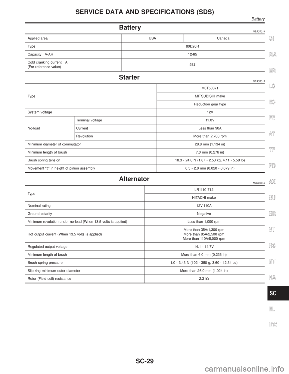
BatteryNBSC0014
Applied area USA Canada
Type80D26R
Capacity V-AH12-65
Cold cranking current A
(For reference value)582
StarterNBSC0015
TypeM0T50371
MITSUBISHI make
Reduction gear type
System voltage12V
No-loadTerminal voltage 11.0V
Current Less than 90A
Revolution More than 2,700 rpm
Minimum diameter of commutator28.8 mm (1.134 in)
Minimum length of brush7.0 mm (0.276 in)
Brush spring tension18.3 - 24.8 N (1.87 - 2.53 kg, 4.11 - 5.58 lb)
Movement ªº in height of pinion assembly 0.5 - 2.0 mm (0.020 - 0.079 in)
AlternatorNBSC0016
TypeLR1110-712
HITACHI make
Nominal rating12V-110A
Ground polarityNegative
Minimum revolution under no-load (When 13.5 volts is applied) Less than 1,000 rpm
Hot output current (When 13.5 volts is applied)More than 35A/1,300 rpm
More than 85A/2,500 rpm
More than 110A/5,000 rpm
Regulated output voltage14.1 - 14.7V
Minimum length of brushMore than 6.0 mm (0.236 in)
Brush spring pressure 1.0 - 3.43 N (102 - 350 g, 3.60 - 12.34 oz)
Slip ring minimum outer diameter More than 26.0 mm (1.024 in)
Rotor (Field coil) resistance2.31W
GI
MA
EM
LC
EC
FE
AT
TF
PD
AX
SU
BR
ST
RS
BT
HA
EL
IDX
SERVICE DATA AND SPECIFICATIONS (SDS)
Battery
SC-29
Page 2214 of 2395

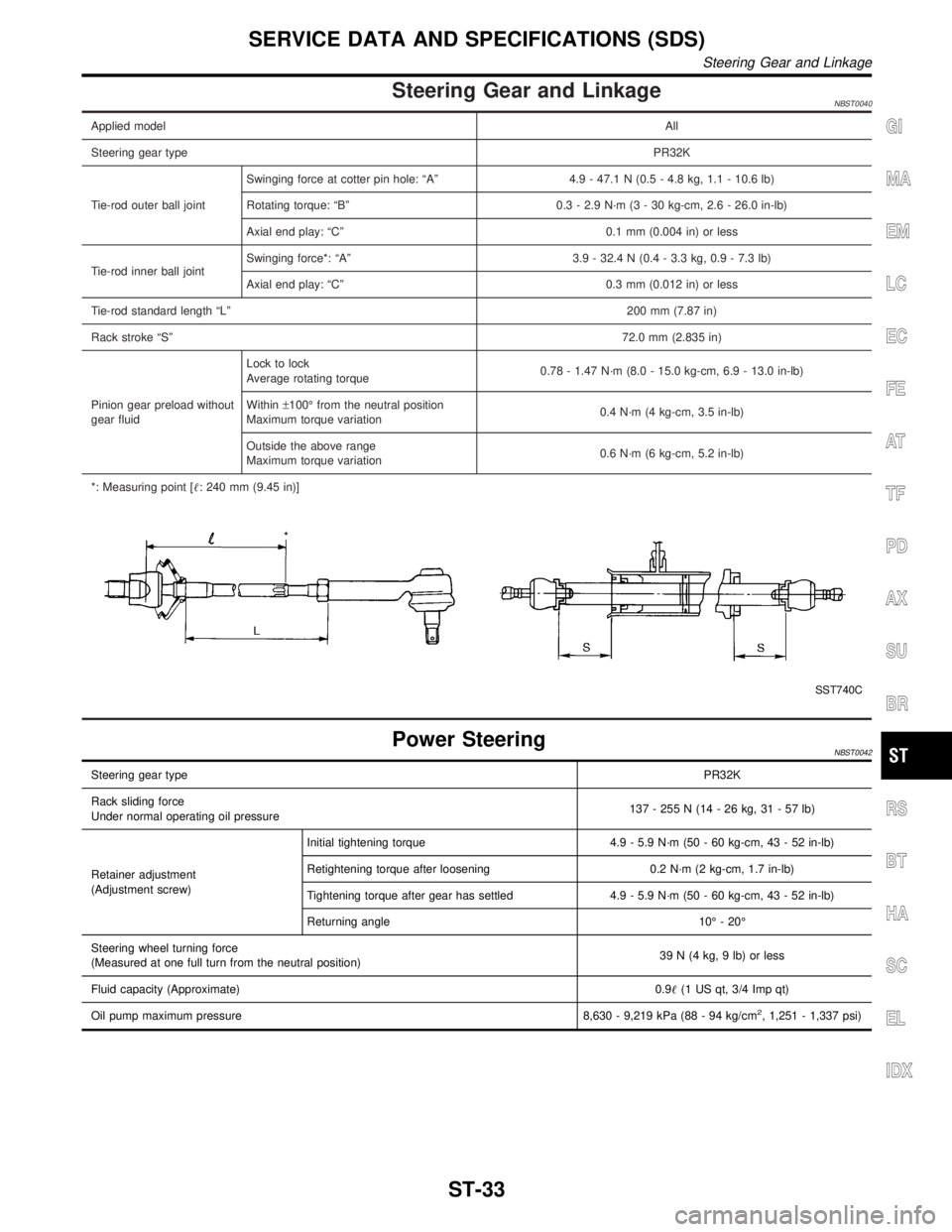
Steering Gear and LinkageNBST0040
Applied modelAll
Steering gear typePR32K
Tie-rod outer ball jointSwinging force at cotter pin hole: ªAº 4.9 - 47.1 N (0.5 - 4.8 kg, 1.1 - 10.6 lb)
Rotating torque: ªBº 0.3 - 2.9 N´m (3 - 30 kg-cm, 2.6 - 26.0 in-lb)
Axial end play: ªCº 0.1 mm (0.004 in) or less
Tie-rod inner ball jointSwinging force*: ªAº 3.9 - 32.4 N (0.4 - 3.3 kg, 0.9 - 7.3 lb)
Axial end play: ªCº 0.3 mm (0.012 in) or less
Tie-rod standard length ªLº200 mm (7.87 in)
Rack stroke ªSº72.0 mm (2.835 in)
Pinion gear preload without
gear fluidLock to lock
Average rotating torque0.78 - 1.47 N´m (8.0 - 15.0 kg-cm, 6.9 - 13.0 in-lb)
Within±100É from the neutral position
Maximum torque variation0.4 N´m (4 kg-cm, 3.5 in-lb)
Outside the above range
Maximum torque variation0.6 N´m (6 kg-cm, 5.2 in-lb)
*: Measuring point [: 240 mm (9.45 in)]
SST740C
Power SteeringNBST0042
Steering gear typePR32K
Rack sliding force
Under normal operating oil pressure137 - 255 N (14 - 26 kg, 31 - 57 lb)
Retainer adjustment
(Adjustment screw)Initial tightening torque 4.9 - 5.9 N´m (50 - 60 kg-cm, 43 - 52 in-lb)
Retightening torque after loosening 0.2 N´m (2 kg-cm, 1.7 in-lb)
Tightening torque after gear has settled 4.9 - 5.9 N´m (50 - 60 kg-cm, 43 - 52 in-lb)
Returning angle 10É - 20É
Steering wheel turning force
(Measured at one full turn from the neutral position)39 N (4 kg, 9 lb) or less
Fluid capacity (Approximate)0.9(1 US qt, 3/4 Imp qt)
Oil pump maximum pressure 8,630 - 9,219 kPa (88 - 94 kg/cm
2, 1,251 - 1,337 psi)
GI
MA
EM
LC
EC
FE
AT
TF
PD
AX
SU
BR
RS
BT
HA
SC
EL
IDX
SERVICE DATA AND SPECIFICATIONS (SDS)
Steering Gear and Linkage
ST-33