ECO mode INFINITI QX4 2001 Factory Service Manual
[x] Cancel search | Manufacturer: INFINITI, Model Year: 2001, Model line: QX4, Model: INFINITI QX4 2001Pages: 2395, PDF Size: 43.2 MB
Page 1125 of 2395

6 DETECT MALFUNCTIONING PART
Check the following.
IHarness connectors B152, B151 and B101, B43
IHarness connectors B1, M2 and M94, F27
IHarness for open or short between vacuum cut valve bypass valve and ECM
©Repair open circuit or short to ground or short to power in harness or connectors.
7 CHECK VACUUM CUT VALVE BYPASS VALVE
With CONSULT-II
1. Reconnect harness disconnected connectors.
2. Turn ignition switch ON.
3. Perform ªVC/V BYPASS/Vº in ªACTIVE TESTº mode.
4. Check air passage continuity and operation delay time under the following conditions.
SEF016Z
Without CONSULT-II
Check air passage continuity and operation delay time under the following conditions.
SEF358X
OK or NG
OK©GO TO 8.
NG©Replace vacuum cut valve bypass valve.
8 CHECK INTERMITTENT INCIDENT
Refer to ªTROUBLE DIAGNOSIS FOR INTERMITTENT INCIDENTº, EC-140.
©INSPECTION END
DTC P1490 VACUUM CUT VALVE BYPASS VALVE (CIRCUIT)
Diagnostic Procedure (Cont'd)
EC-590
Page 1127 of 2395

On Board Diagnosis LogicNBEC0356Malfunction is detected when vacuum cut valve bypass valve does
not operate properly.
Possible CauseNBEC0593IVacuum cut valve bypass valve
IVacuum cut valve
IBypass hoses for clogging
IEVAP control system pressure sensor and circuit
IEVAP canister vent control valve
IHose between fuel tank and vacuum cut valve clogged
IHose between vacuum cut valve and EVAP canister clogged
IEVAP canister
IEVAP purge port of fuel tank for clogging
SEF210Y
SEF211Y
SEF239Y
DTC Confirmation ProcedureNBEC0357CAUTION:
Always drive vehicle at a safe speed.
NOTE:
If ªDTC Confirmation Procedureº has been previously conducted,
always turn ignition switch ªOFFº and wait at least 10 seconds
before conducting the next test.
TESTING CONDITION:
For best results, perform test at a temperature of 5 to 30ÉC (41
to 86ÉF).
WITH CONSULT-IINBEC0357S011) Turn ignition switch ªONº.
2) Start engine and warm it up to normal operating temperature.
3) Turn ignition switch ªOFFº and wait at least 10 seconds.
4) Start engine and let it idle for at least 70 seconds.
5) Select ªVC CUT/V BP/V P1491º of ªEVAPORATIVE SYSTEMº
in ªDTC WORK SUPPORTº mode with CONSULT-II.
6) Touch ªSTARTº.
7) When the following conditions are met, ªTESTINGº will be dis-
played on the CONSULT-II screen. Maintain the conditions
continuously until ªTESTINGº changes to ªCOMPLETEDº. (It
will take at least 30 seconds.)
ENG SPEED Idle speed or more
Selector lever Suitable position
Vehicle speed 37 km/h (23 MPH) or more
B/FUEL SCHDL 1.3 - 10 msec
If ªTESTINGº is not displayed after 5 minutes, retry from
step 3.
8) Make sure that ªOKº is displayed after touching ªSELF-DIAG
DTC P1491 VACUUM CUT VALVE BYPASS VALVE
On Board Diagnosis Logic
EC-592
Page 1136 of 2395

14 CHECK EVAP CANISTER VENT CONTROL VALVE-I
1. Remove EVAP canister vent control valve from EVAP canister.
2. Check portionBof EVAP canister vent control valve for being rusted.
SEF337X
OK or NG
OK©GO TO 15.
NG©Replace EVAP canister vent control valve.
15 CHECK EVAP CANISTER VENT CONTROL VALVE-II
With CONSULT-II
1. Reconnect harness disconnected connectors.
2. Turn ignition switch ON.
3. Perform ªVENT CONTROL/Vº in ªACTIVE TESTº mode.
4. Check air passage continuity and operation delay time.
SEF991Y
Without CONSULT-II
Check air passage continuity and operation delay time under the following conditions.
SEF339X
Make sure new O-ring is installed properly.
OK or NG
OK©GO TO 17.
NG©GO TO 16.
GI
MA
EM
LC
FE
AT
TF
PD
AX
SU
BR
ST
RS
BT
HA
SC
EL
IDX
DTC P1491 VACUUM CUT VALVE BYPASS VALVE
Diagnostic Procedure (Cont'd)
EC-601
Page 1138 of 2395

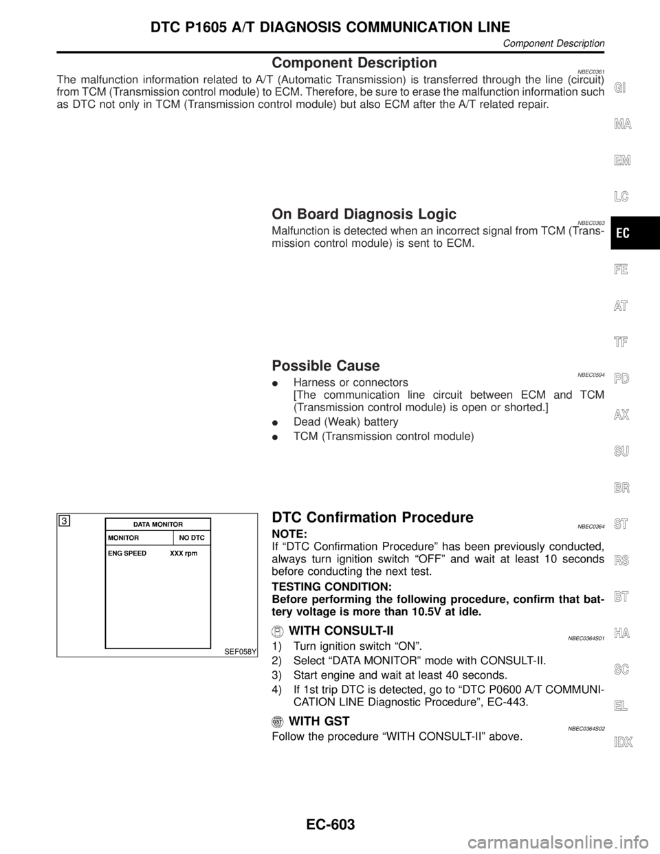
Component DescriptionNBEC0361The malfunction information related to A/T (Automatic Transmission) is transferred through the line (circuit)
from TCM (Transmission control module) to ECM. Therefore, be sure to erase the malfunction information such
as DTC not only in TCM (Transmission control module) but also ECM after the A/T related repair.
On Board Diagnosis LogicNBEC0363Malfunction is detected when an incorrect signal from TCM (Trans-
mission control module) is sent to ECM.
Possible CauseNBEC0594IHarness or connectors
[The communication line circuit between ECM and TCM
(Transmission control module) is open or shorted.]
IDead (Weak) battery
ITCM (Transmission control module)
SEF058Y
DTC Confirmation ProcedureNBEC0364NOTE:
If ªDTC Confirmation Procedureº has been previously conducted,
always turn ignition switch ªOFFº and wait at least 10 seconds
before conducting the next test.
TESTING CONDITION:
Before performing the following procedure, confirm that bat-
tery voltage is more than 10.5V at idle.
WITH CONSULT-IINBEC0364S011) Turn ignition switch ªONº.
2) Select ªDATA MONITORº mode with CONSULT-II.
3) Start engine and wait at least 40 seconds.
4) If 1st trip DTC is detected, go to ªDTC P0600 A/T COMMUNI-
CATION LINE Diagnostic Procedureº, EC-443.
WITH GSTNBEC0364S02Follow the procedure ªWITH CONSULT-IIº above.
GI
MA
EM
LC
FE
AT
TF
PD
AX
SU
BR
ST
RS
BT
HA
SC
EL
IDX
DTC P1605 A/T DIAGNOSIS COMMUNICATION LINE
Component Description
EC-603
Page 1140 of 2395

DTC Confirmation ProcedureNBEC0371CAUTION:
Always drive vehicle at a safe speed.
NOTE:
If ªDTC Confirmation Procedureº has been previously conducted,
always turn ignition switch ªOFFº and wait at least 10 seconds
before conducting the next test.
SEF212Y
SEF213Y
WITH CONSULT-IINBEC0371S011) Turn ignition switch ªONº.
2) Select ªP/N POSI SWº in ªDATA MONITORº mode with CON-
SULT-II. Then check the ªP/N POSI SWº signal under the fol-
lowing conditions.
Position (Selector lever) Known-good signal
ªNº and ªPº position ON
Except the above position OFF
If NG, go to ªDiagnostic Procedureº, EC-608.
If OK, go to following step.
3) Select ªDATA MONITORº mode with CONSULT-II.
4) Start engine and warm it up to normal operating temperature.
5) Maintain the following conditions for at least 60 consecutive
seconds.
ENG SPEED 1,500 - 2,500 rpm
COOLAN TEMP/S More than 70ÉC (158ÉF)
B/FUEL SCHDL 3.6 - 12 msec
VHCL SPEED SE 70 - 100 km/h (43 - 62 MPH)
Selector lever Suitable position
6) If 1st trip DTC is detected, go to ªDiagnostic Procedureº,
EC-608.
GI
MA
EM
LC
FE
AT
TF
PD
AX
SU
BR
ST
RS
BT
HA
SC
EL
IDX
DTC P1706 PARK/NEUTRAL POSITION (PNP) SWITCH
DTC Confirmation Procedure
EC-605
Page 1160 of 2395

System DescriptionNBEC0392
Sensor Input Signal to ECMECM func-
tionActuator
Crankshaft position sensor (POS) Engine speed (POS signal)
Fuel pump
controlFuel pump relay Crankshaft position sensor (REF) Engine speed (REF signal)
Ignition switch Start signal
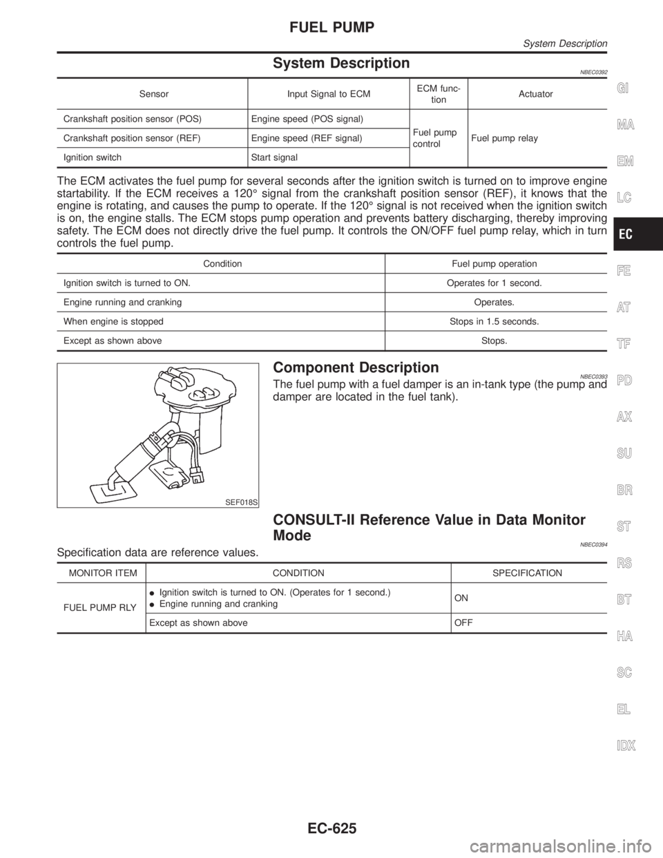
The ECM activates the fuel pump for several seconds after the ignition switch is turned on to improve engine
startability. If the ECM receives a 120É signal from the crankshaft position sensor (REF), it knows that the
engine is rotating, and causes the pump to operate. If the 120É signal is not received when the ignition switch
is on, the engine stalls. The ECM stops pump operation and prevents battery discharging, thereby improving
safety. The ECM does not directly drive the fuel pump. It controls the ON/OFF fuel pump relay, which in turn
controls the fuel pump.
Condition Fuel pump operation
Ignition switch is turned to ON. Operates for 1 second.
Engine running and cranking Operates.
When engine is stopped Stops in 1.5 seconds.
Except as shown aboveStops.
SEF018S
Component DescriptionNBEC0393The fuel pump with a fuel damper is an in-tank type (the pump and
damper are located in the fuel tank).
CONSULT-II Reference Value in Data Monitor
Mode
NBEC0394Specification data are reference values.
MONITOR ITEM CONDITION SPECIFICATION
FUEL PUMP RLYIIgnition switch is turned to ON. (Operates for 1 second.)
IEngine running and crankingON
Except as shown above OFF
GI
MA
EM
LC
FE
AT
TF
PD
AX
SU
BR
ST
RS
BT
HA
SC
EL
IDX
FUEL PUMP
System Description
EC-625
Page 1167 of 2395

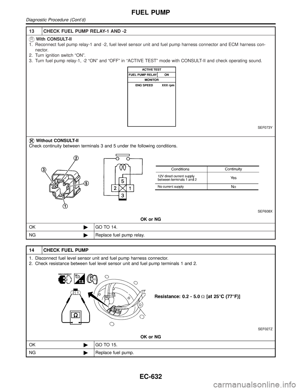
13 CHECK FUEL PUMP RELAY-1 AND -2
With CONSULT-II
1. Reconnect fuel pump relay-1 and -2, fuel level sensor unit and fuel pump harness connector and ECM harness con-
nector.
2. Turn ignition switch ªONº.
3. Turn fuel pump relay-1, -2 ªONº and ªOFFº in ªACTIVE TESTº mode with CONSULT-II and check operating sound.
SEF073Y
Without CONSULT-II
Check continuity between terminals 3 and 5 under the following conditions.
SEF608X
OK or NG
OK©GO TO 14.
NG©Replace fuel pump relay.
14 CHECK FUEL PUMP
1. Disconnect fuel level sensor unit and fuel pump harness connector.
2. Check resistance between fuel level sensor unit and fuel pump terminals 1 and 2.
SEF027Z
OK or NG
OK©GO TO 15.
NG©Replace fuel pump.
FUEL PUMP
Diagnostic Procedure (Cont'd)
EC-632
Page 1279 of 2395

Component Parts and Harness Connector
Location
NBEL0041
SEL351X
System DescriptionNBEL0042UNIFIED CONTROL METERNBEL0042S06ISpeedometer, odo/trip meter, tachometer, fuel gauge and water temperature gauge are controlled totally
by control unit.
IDigital meter is adopted for odo/trip meter.*
*The record of the odo meter is kept even if the battery cable is disconnected. The record of the trip meter
is erased when the battery cable is disconnected.
IOdo/trip meter is indicated for about 30 seconds after ignition switch has been turned OFF.
IOdo/trip meter segment can be checked in diagnosis mode.
IMeter/gauge can be checked in diagnosis mode.
HOW TO CHANGE THE DISPLAY FOR ODO/TRIP METERNBEL0042S07
SEL175W
NOTE:
Turn ignition switch to the ªONº position to operate odo/trip meter.
METERS AND GAUGES
Component Parts and Harness Connector Location
EL-94
Page 1285 of 2395

Meter/Gauge Operation and Odo/Trip Meter
Segment Check in Diagnosis Mode
NBEL0200DIAGNOSIS FUNCTIONNBEL0200S01IOdo/trip meter segment can be checked in diagnosis mode.
IMeters/gauges can be checked in diagnosis mode.
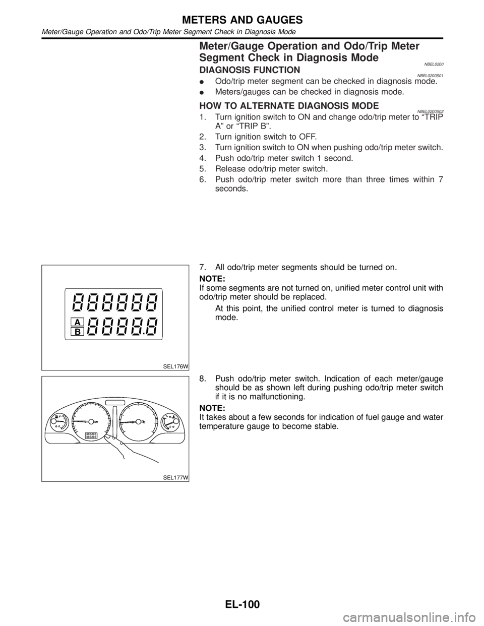
HOW TO ALTERNATE DIAGNOSIS MODENBEL0200S021. Turn ignition switch to ON and change odo/trip meter to ªTRIP
Aº or ªTRIP Bº.
2. Turn ignition switch to OFF.
3. Turn ignition switch to ON when pushing odo/trip meter switch.
4. Push odo/trip meter switch 1 second.
5. Release odo/trip meter switch.
6. Push odo/trip meter switch more than three times within 7
seconds.
SEL176W
7. All odo/trip meter segments should be turned on.
NOTE:
If some segments are not turned on, unified meter control unit with
odo/trip meter should be replaced.
At this point, the unified control meter is turned to diagnosis
mode.
SEL177W
8. Push odo/trip meter switch. Indication of each meter/gauge
should be as shown left during pushing odo/trip meter switch
if it is no malfunctioning.
NOTE:
It takes about a few seconds for indication of fuel gauge and water
temperature gauge to become stable.
METERS AND GAUGES
Meter/Gauge Operation and Odo/Trip Meter Segment Check in Diagnosis Mode
EL-100
Page 1297 of 2395

Trouble DiagnosesNBEL0048PRELIMINARY CHECK FOR THERMOMETERNBEL0048S02
1 COOL DOWN CHECK
1. Turn the ignition key switch to the ªACCº position.
2. Cool down the ambient air temperature sensor with water or ice, so that the indicated temperature falls.
Does the indicated temperature fall?
Ye s©GO TO 2.
No©The system is malfunctioning. Check the system following ªINSPECTION/COMPASS
AND THERMOMETERº.
2 WARM UP CHECK
1. Leave the vehicle for 10 minutes, so that the indicated temperature rises.
2. With the ignition key in the ªACCº position, disconnect and reconnect the ambient air temperature sensor connector.
Does the indicated temperature rise?
Ye s©The system is OK.
No©The system is malfunctioning. Check the system following ªINSPECTION/COMPASS
AND THERMOMETERº.
NOTE:
IWhen the outside temperature is between 55ÉC (130ÉF) and 70ÉC (158ÉF), the display shows 55ÉC
(130ÉF). When the outside temperature is lower than þ30ÉC (þ20ÉF) or higher than 70ÉC (158ÉF), the dis-
play shows only ª---º.
IThe indicated temperature on the thermometer is not readily affected by engine heat. It changes only when
one of the following conditions is present.
a) The temperature detected by the ambient air temperature sensor is lower than the indicated temperature
on the thermometer.
b) The difference in temperature detected during a period of 40 seconds is less than 1ÉC (1.8ÉF) when vehicle
speed has been greater than 24 km/h (15 MPH) for more than 100 seconds.
(This is to prevent the indicated temperature from being affected by engine heat or cooling fan operation
during low-speed driving.)
c) The ignition key has been turned to the ªOFFº position for more than 4 hours. (The engine is cold.)
INSPECTION/COMPASS AND THERMOMETERNBEL0048S01
Symptom Possible causes Repair order
No display at all 1. 10A fuse
2. Ground circuit
3. Compass and thermometer1. Check 10A fuse [No. 9, located in fuse block (J/B)].
Turn the ignition switch ON and verify that battery positive
voltage is at terminal 7 of compass and thermometer.
2. Check ground circuit for compass and thermometer.
3. Replace compass and thermometer.
Forward direction indi-
cation slips off the
mark or incorrect.1. In manual correction mode (Bar
and display vanish.)
2. Zone variation change is not done.1. Drive the vehicle and turn at an angle of 90É.
2. Perform the zone variation change.
Compass reading
remains unchanged.1. Vehicle speed sensor is not
entered.
2. Compass and thermometer1. Check harness for open or short between combination meter
terminal 13 and compass and thermometer terminal 1.
2. Replace compass and thermometer.
Displays wrong tem-
perature when ambient
temperature is between
þ30ÉC (þ20ÉF) and
55ÉC (130ÉF). (See
NOTE above.)1. Check operation
2. Ambient air temperature sensor
circuit
3. Vehicle speed sensor is not
entered.
4. Ambient air temperature sensor
5. Compass and thermometer1. Perform preliminary check shown above.
2. Check harness for open or short between ambient air tem-
perature sensor and compass and thermometer.
3. Check harness for open or short between combination meter
terminal 13 and compass and thermometer terminal 1.
4. Replace ambient air temperature sensor.
5. Replace compass and thermometer.
COMPASS AND THERMOMETER
Trouble Diagnoses
EL-112