clutch INFINITI QX4 2001 Factory Service Manual
[x] Cancel search | Manufacturer: INFINITI, Model Year: 2001, Model line: QX4, Model: INFINITI QX4 2001Pages: 2395, PDF Size: 43.2 MB
Page 2346 of 2395

NBTF0038
SMT858D
4WD Shift SwitchNBTF0038S01Check continuity between each terminal.
Terminals Switch position Continuity
1-22WD Yes
Except 2WD No
1-3,1-4AUTO Yes
Except AUTO No
1-4,1-54H Yes
Except 4H No
1-4,1-64LO Yes
Except 4LO No
SMT079D
2-4WD Shift Solenoid Valve and Transfer Fluid
Temperature Sensor
NBTF0038S02Measure resistance between terminals of transfer terminal cord
assembly sub-harness connector located on rear-right of transfer
unit.
Component parts Terminals Resistance
2-4WD shift solenoid valve 4 - 5Approx. 20ÉC (68ÉF):
Approx. 22.8 - 25.2W
Transfer fluid temperature
sensor2-3Approx. 20ÉC (68ÉF): Approx. 2.5 kW
Approx. 80ÉC (176ÉF): Approx. 0.3
kW
SMT080D
4WD Solenoid Valve, Clutch Pressure Switch
and Line Pressure Switch
NBTF0038S03Measure resistance between terminals of transfer terminal cord
assembly sub-harness connector located on rear-right of transfer
unit.
GI
MA
EM
LC
EC
FE
AT
PD
AX
SU
BR
ST
RS
BT
HA
SC
EL
IDX
COMPONENT INSPECTION
4WD Shift Switch
TF-111
Page 2347 of 2395

Component
partsTerminals Remarks
4WD solenoid
valve6
Ground
terminalApprox. 20ÉC (68ÉF): Approx. 3.0 - 3.4W
Clutch pres-
sure switch7In room temperature
I2-4WD shift solenoid valve ªOFFº: No
continuity
I2-4WD shift solenoid valve and transfer
motor ªONº: Continuity exists
Line pressure
switch1In room temperature
ITurn ignition switch to ªOFFº position
and leave vehicle for more than 5 min-
utes. (OFF): No continuity
ITransfer motor ªONº: Continuity exists
SMT081D
Front Revolution SensorNBTF0038S04Measure resistance between terminals of front revolution sensor
sub-harness connector located on rear-right of transfer unit.
Terminals Resistance
16 - 17 500 - 650W
18 - 17 No continuity
18 - 16 No continuity
SMT806D
Transfer Dropping ResistorNBTF0038S07Check resistance between terminals.
Resistance: 11.2 - 12.8W
SMT083D
ATP Switch, Neutral-4LO Switch and Wait
Detection Switch
NBTF0038S06Measure resistance between terminals of transfer switch assembly
sub-harness connector located on rear-right of transfer unit.
COMPONENT INSPECTION
4WD Solenoid Valve, Clutch Pressure Switch and Line Pressure Switch (Cont'd)
TF-112
Page 2349 of 2395

SMT087D
TRANSFER SWITCH ASSEMBLY SUB-HARNESS
CONNECTOR
NBTF0038S0902Check continuity between terminals shown in the figure.
SMT088D
TRANSFER TERMINAL CORD ASSEMBLY
SUB-HARNESS CONNECTOR
NBTF0038S0903Check continuity between terminals shown in the figure.
Terminals on solenoid valve
Terminals Components
6 4WD solenoid valve
4, 5 2-4WD shift solenoid valve
2, 3 Transfer fluid temperature sensor
7 Clutch pressure switch
1 Line pressure switch
SMT807D
Transfer Shift Relay (High & low)NBTF0038S10Check continuity between terminals 3 and 4.
Condition Continuity
12V direct current supply
between terminals 1 and 2No
No current supply Yes
COMPONENT INSPECTION
Transfer Sub-harness (Cont'd)
TF-114
Page 2356 of 2395

Transfer ComponentsNBTF0076
SMT810D
1. Oil seal
2. Transfer cover
3. Snap ring
4. Washer
5. Snap ring
6. Main gear bearing
7. Front case
8. Check plug
9. Check spring
10. Check ball
11. Internal gear
12. Snap ring
13. Bearing race
14. Thrust needle bearing
15. Planetary carrier
16. Thrust needle bearing
17. Sun gear18. L-H sleeve
19. 2-4 sleeve
20. Radial needle bearing
21. Front revolution sensor
22. Roll pin
23. L-H fork
24. 2-4 fork
25. Shift fork spring
26. Fork guide
27. Roll pin
28. Shift rod
29. Self-lock nut
30. Companion flange
31. Oil seal
32. Drain plug
33. Wait detection switch
34. Needle bearing35. Mainshaft
36. Drive chain
37. Clutch drum
38. Clutch hub
39. Snap ring
40. Driven plate
41. Drive plate
42. Retaining plate
43. Return spring assembly
44. Press flange
45. Washer
46. Thrust needle bearing
47. Snap ring
48. Seal ring
49. Front bearing
50. Front drive shaft
51. Rear bearing
GI
MA
EM
LC
EC
FE
AT
PD
AX
SU
BR
ST
RS
BT
HA
SC
EL
IDX
OVERHAUL
Transfer Components
TF-121
Page 2357 of 2395

SMT811D
55. Thrust needle bearing race
56. Clutch piston
57. D-ring
58. Lip seal
59. Oil gutter
60. Center case
61. Stem bleeder
62. Mainshaft rear bearing
63. Thrust washer
64. Speedometer drive gear
65. Snap ring
66. Rear case
67. ATP switch
68. Neutral-4LO switch69. Oil seal
70. Magnet
71. Baffle plate
72. Oil strainer
73. O-ring
74. Control valve assembly
75. Lip seal (7 pieces)
76. Filler plug
77. Inner gear
78. Outer gear
79. Oil pump housing
80. Bushing
81. Oil pump shaft
82. Oil pressure check plug83. Oil pump gasket
84. Sub-oil pump housing
85. Outer gear
86. Inner gear
87. O-ring
88. Sub-oil pump cover
89. O-ring
90. Transfer motor
91. O-ring
92. Oil filter stud
93. O-ring
94. O-ring
95. Oil filter
OVERHAUL
Transfer Components (Cont'd)
TF-122
Page 2360 of 2395

SMT900C
Front Drive Shaft and Drive ChainNBTF0078S011. Remove oil gutter from center case.
2. With front drive shaft held by one hand as shown in the figure,
tap center case with a plastic hammer to remove it with drive
chain.
IDo not tap drive chain with a plastic hammer.
SMT901CB
3. Set a puller (ST30021000) and an adapter (ST33052000).
Remove front drive shaft front bearing.
SMT902CB
4. Set the puller (ST30021000) and the adapter (ST33052000).
Remove front drive shaft rear bearing.
SMT903CA
Mainshaft and Clutch DrumNBTF0078S021. Remove mounting bolts to detach baffle plate.
SMT904C
2. Set center case to press stand. Remove mainshaft from cen-
ter case.
GI
MA
EM
LC
EC
FE
AT
PD
AX
SU
BR
ST
RS
BT
HA
SC
EL
IDX
DISASSEMBLY
Center Case (Cont'd)
TF-125
Page 2362 of 2395

SMT910C
8. Remove press flange from mainshaft.
SMT911C
9. Remove return spring assembly from clutch hub.
SMT912C
10. Remove each plate from clutch drum.
SMT913C
11. Remove snap ring from mainshaft.
IDo not reuse snap ring.
SMT914C
12. Tap mainshaft with a plastic hammer to remove it from clutch
drum and clutch hub.
13. Remove needle bearing from mainshaft.
GI
MA
EM
LC
EC
FE
AT
PD
AX
SU
BR
ST
RS
BT
HA
SC
EL
IDX
DISASSEMBLY
Center Case (Cont'd)
TF-127
Page 2363 of 2395

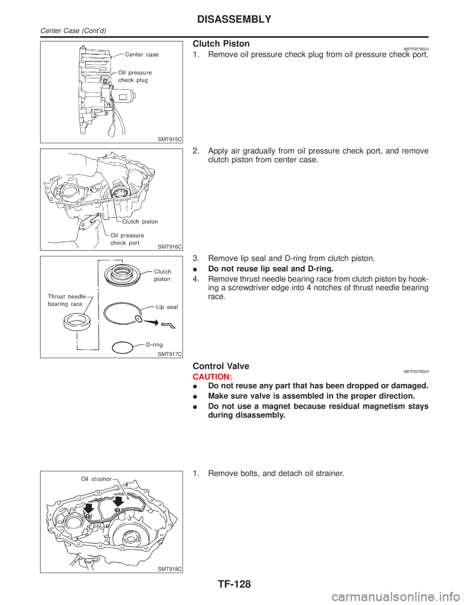
SMT915C
Clutch PistonNBTF0078S031. Remove oil pressure check plug from oil pressure check port.
SMT916C
2. Apply air gradually from oil pressure check port, and remove
clutch piston from center case.
SMT917C
3. Remove lip seal and D-ring from clutch piston.
IDo not reuse lip seal and D-ring.
4. Remove thrust needle bearing race from clutch piston by hook-
ing a screwdriver edge into 4 notches of thrust needle bearing
race.
Control ValveNBTF0078S04CAUTION:
IDo not reuse any part that has been dropped or damaged.
IMake sure valve is assembled in the proper direction.
IDo not use a magnet because residual magnetism stays
during disassembly.
SMT918C
1. Remove bolts, and detach oil strainer.
DISASSEMBLY
Center Case (Cont'd)
TF-128
Page 2365 of 2395

SMT924C
7. Remove 4WD solenoid valve, clutch pressure switch, 2-4WD
shift solenoid valve, line pressure switch, and transfer fluid
temperature sensor from control valve assembly.
8. Remove O-rings from each solenoid valve, switch and termi-
nal body.
IDo not reuse O-rings.
SMT925C
9. Place control valve with lower body facing up, remove two
mounting bolts, and then remove lower body and separator
plate from upper body.
CAUTION:
IBe careful not to drop relief balls. Detach lower body care-
fully.
IDo not reuse separator plate.
SMT926C
10. Make sure reverse balls, relief balls and relief springs, accu-
mulator pistons, valve springs, and filters are securely installed
as shown in the figure, and remove them.
SMT927C
11. Remove retainer plates.
SMT928CA
12. Remove each control valve, spring and plug.
DISASSEMBLY
Center Case (Cont'd)
TF-130
Page 2373 of 2395

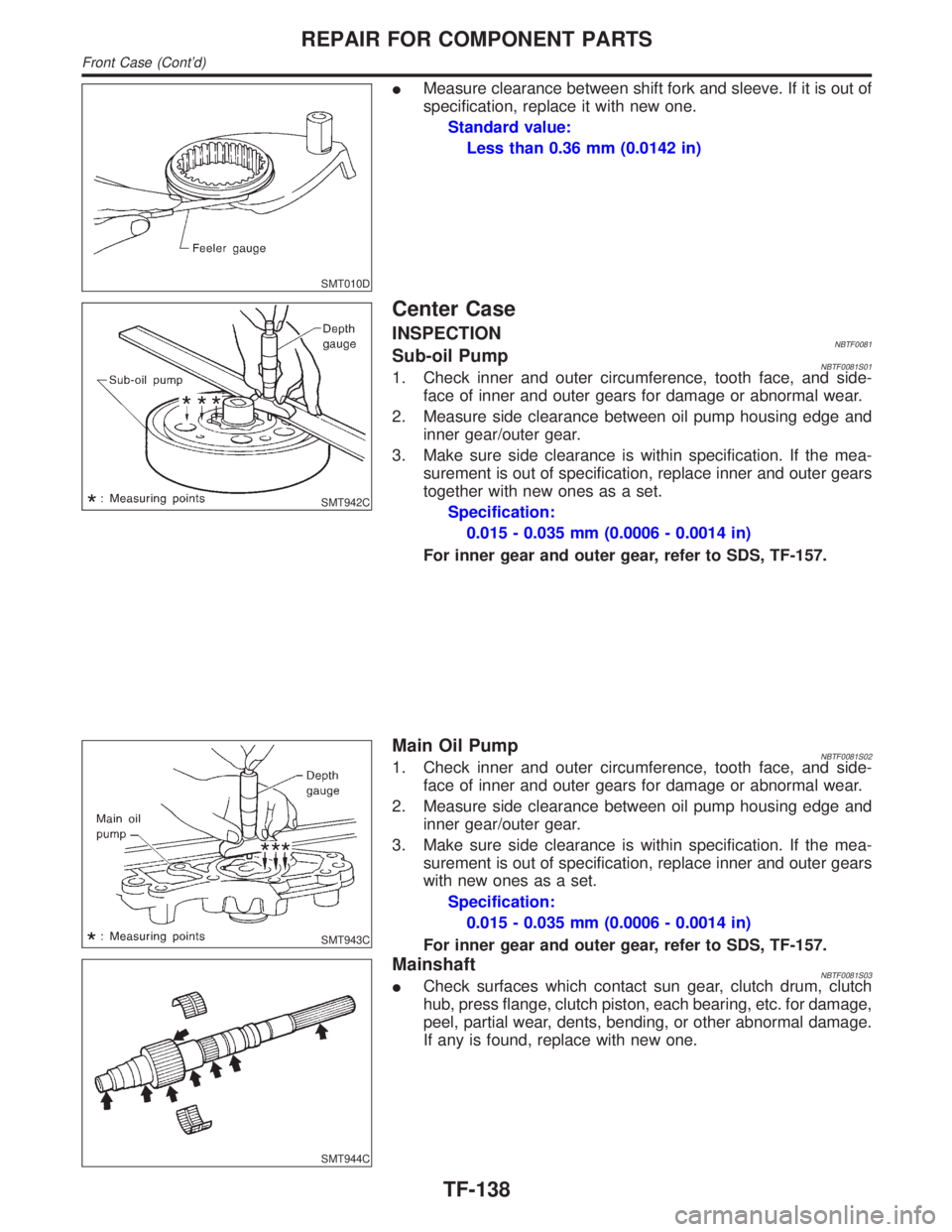
SMT010D
IMeasure clearance between shift fork and sleeve. If it is out of
specification, replace it with new one.
Standard value:
Less than 0.36 mm (0.0142 in)
SMT942C
Center Case
INSPECTIONNBTF0081Sub-oil PumpNBTF0081S011. Check inner and outer circumference, tooth face, and side-
face of inner and outer gears for damage or abnormal wear.
2. Measure side clearance between oil pump housing edge and
inner gear/outer gear.
3. Make sure side clearance is within specification. If the mea-
surement is out of specification, replace inner and outer gears
together with new ones as a set.
Specification:
0.015 - 0.035 mm (0.0006 - 0.0014 in)
For inner gear and outer gear, refer to SDS, TF-157.
SMT943C
Main Oil PumpNBTF0081S021. Check inner and outer circumference, tooth face, and side-
face of inner and outer gears for damage or abnormal wear.
2. Measure side clearance between oil pump housing edge and
inner gear/outer gear.
3. Make sure side clearance is within specification. If the mea-
surement is out of specification, replace inner and outer gears
with new ones as a set.
Specification:
0.015 - 0.035 mm (0.0006 - 0.0014 in)
For inner gear and outer gear, refer to SDS, TF-157.
SMT944C
MainshaftNBTF0081S03ICheck surfaces which contact sun gear, clutch drum, clutch
hub, press flange, clutch piston, each bearing, etc. for damage,
peel, partial wear, dents, bending, or other abnormal damage.
If any is found, replace with new one.
REPAIR FOR COMPONENT PARTS
Front Case (Cont'd)
TF-138