width INFINITI QX4 2001 Factory Service Manual
[x] Cancel search | Manufacturer: INFINITI, Model Year: 2001, Model line: QX4, Model: INFINITI QX4 2001Pages: 2395, PDF Size: 43.2 MB
Page 300 of 2395
SAT039B
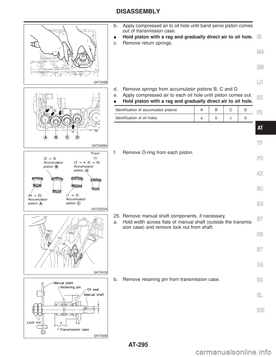
b. Apply compressed air to oil hole until band servo piston comes
out of transmission case.
IHold piston with a rag and gradually direct air to oil hole.
c. Remove return springs.
SAT040BA
d. Remove springs from accumulator pistons B, C and D.
e. Apply compressed air to each oil hole until piston comes out.
IHold piston with a rag and gradually direct air to oil hole.
Identification of accumulator pistons A B C D
Identification of oil holes a b c d
SAT523GA
f. Remove O-ring from each piston.
SAT041B
25. Remove manual shaft components, if necessary.
a. Hold width across flats of manual shaft (outside the transmis-
sion case) and remove lock nut from shaft.
SAT042B
b. Remove retaining pin from transmission case.
GI
MA
EM
LC
EC
FE
TF
PD
AX
SU
BR
ST
RS
BT
HA
SC
EL
IDX
DISASSEMBLY
AT-295
Page 472 of 2395
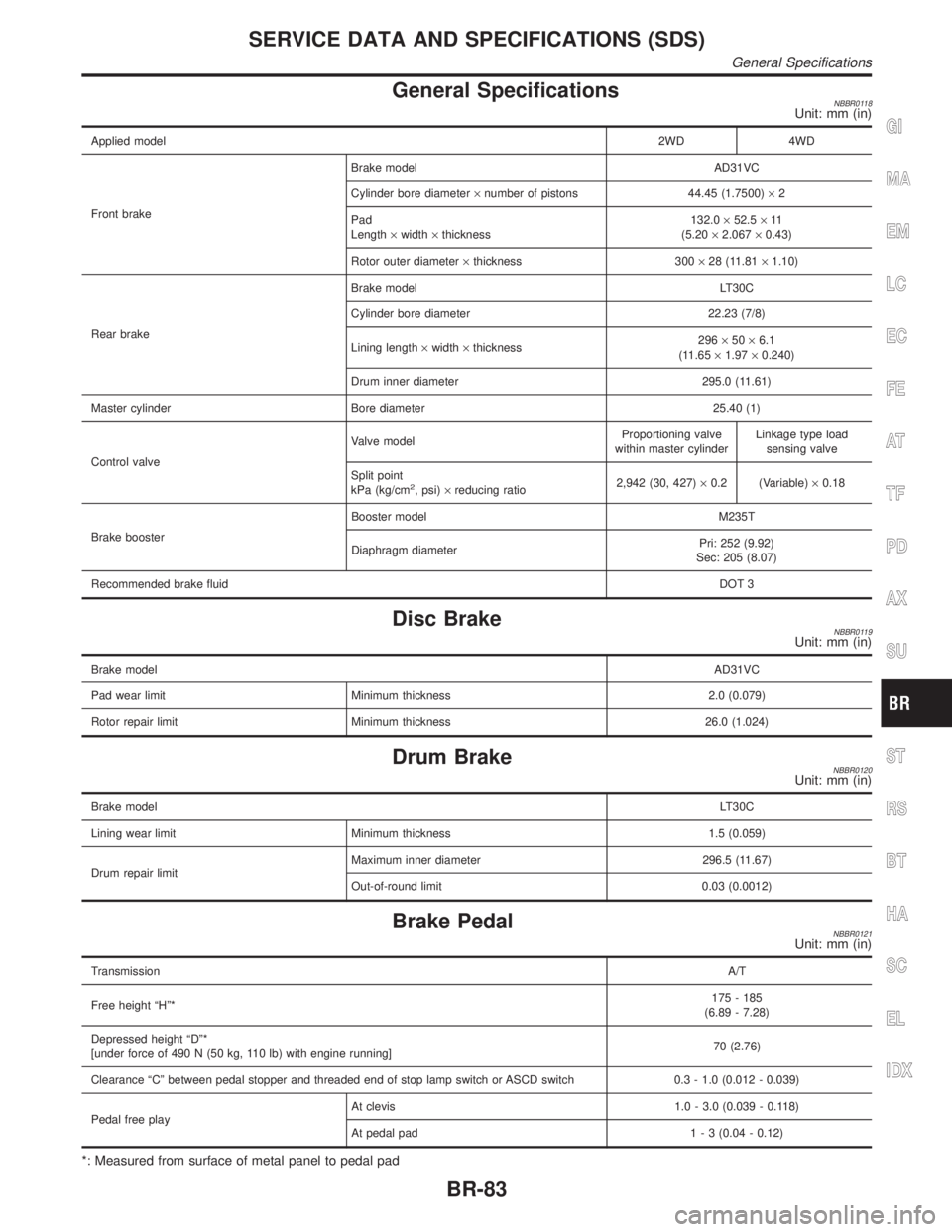
General SpecificationsNBBR0118Unit: mm (in)
Applied model2WD 4WD
Front brakeBrake model AD31VC
Cylinder bore diameter´number of pistons 44.45 (1.7500)´2
Pad
Length´width´thickness132.0´52.5´11
(5.20´2.067´0.43)
Rotor outer diameter´thickness 300´28 (11.81´1.10)
Rear brakeBrake model LT30C
Cylinder bore diameter 22.23 (7/8)
Lining length´width´thickness296´50´6.1
(11.65´1.97´0.240)
Drum inner diameter 295.0 (11.61)
Master cylinder Bore diameter 25.40 (1)
Control valveValve modelProportioning valve
within master cylinderLinkage type load
sensing valve
Split point
kPa (kg/cm
2, psi)´reducing ratio2,942 (30, 427)´0.2 (Variable)´0.18
Brake boosterBooster model M235T
Diaphragm diameterPri: 252 (9.92)
Sec: 205 (8.07)
Recommended brake fluidDOT 3
Disc BrakeNBBR0119Unit: mm (in)
Brake modelAD31VC
Pad wear limit Minimum thickness 2.0 (0.079)
Rotor repair limit Minimum thickness 26.0 (1.024)
Drum BrakeNBBR0120Unit: mm (in)
Brake modelLT30C
Lining wear limit Minimum thickness 1.5 (0.059)
Drum repair limitMaximum inner diameter 296.5 (11.67)
Out-of-round limit 0.03 (0.0012)
Brake PedalNBBR0121Unit: mm (in)
TransmissionA/T
Free height ªHº*175 - 185
(6.89 - 7.28)
Depressed height ªDº*
[under force of 490 N (50 kg, 110 lb) with engine running]70 (2.76)
Clearance ªCº between pedal stopper and threaded end of stop lamp switch or ASCD switch 0.3 - 1.0 (0.012 - 0.039)
Pedal free playAt clevis 1.0 - 3.0 (0.039 - 0.118)
At pedal pad1 - 3 (0.04 - 0.12)
*: Measured from surface of metal panel to pedal pad
GI
MA
EM
LC
EC
FE
AT
TF
PD
AX
SU
ST
RS
BT
HA
SC
EL
IDX
SERVICE DATA AND SPECIFICATIONS (SDS)
General Specifications
BR-83
Page 564 of 2395

Mixture Ratio Feedback Control (Closed loop control)NBEC0014S04
SEF336WA
The mixture ratio feedback system provides the best air-fuel mixture ratio for driveability and emission con-
trol. The warm-up three way catalyst can then better reduce CO, HC and NOx emissions. This system uses
a heated oxygen sensor 1 (front) in the exhaust manifold to monitor if the engine operation is rich or lean. The
ECM adjusts the injection pulse width according to the sensor voltage signal. For more information about the
heated oxygen sensor 1 (front), refer to EC-192. This maintains the mixture ratio within the range of stoichio-
metric (ideal air-fuel mixture).
This stage is referred to as the closed loop control condition.
Heated oxygen sensor 2 (rear) is located downstream of the warm-up three way catalyst. Even if the switch-
ing characteristics of the heated oxygen sensor 1 (front) shift, the air-fuel ratio is controlled to stoichiometric
by the signal from the heated oxygen sensor 2 (rear).
Open Loop ControlNBEC0014S05The open loop system condition refers to when the ECM detects any of the following conditions. Feedback
control stops in order to maintain stabilized fuel combustion.
IDeceleration and acceleration
IHigh-load, high-speed operation
IMalfunction of heated oxygen sensor 1 (front) or its circuit
IInsufficient activation of heated oxygen sensor 1 (front) at low engine coolant temperature
IHigh engine coolant temperature
IDuring warm-up
IAfter shifting from ªNº to ªDº
IWhen starting the engine
Mixture Ratio Self-learning ControlNBEC0014S06The mixture ratio feedback control system monitors the mixture ratio signal transmitted from the heated oxy-
gen sensor 1 (front). This feedback signal is then sent to the ECM. The ECM controls the basic mixture ratio
as close to the theoretical mixture ratio as possible. However, the basic mixture ratio is not necessarily con-
trolled as originally designed. Both manufacturing differences (i.e., mass air flow sensor hot wire) and char-
acteristic changes during operation (i.e., injector clogging) directly affect mixture ratio.
Accordingly, the difference between the basic and theoretical mixture ratios is monitored in this system. This
is then computed in terms of ªinjection pulse durationº to automatically compensate for the difference between
the two ratios.
ªFuel trimº refers to the feedback compensation value compared against the basic injection duration. Fuel trim
includes short term fuel trim and long term fuel trim.
ªShort term fuel trimº is the short-term fuel compensation used to maintain the mixture ratio at its theoretical
value. The signal from the heated oxygen sensor 1 (front) indicates whether the mixture ratio is RICH or LEAN
compared to the theoretical value. The signal then triggers a reduction in fuel volume if the mixture ratio is
rich, and an increase in fuel volume if it is lean.
ªLong term fuel trimº is overall fuel compensation carried out long-term to compensate for continual deviation
of the short term fuel trim from the central value. Such deviation will occur due to individual engine differences,
wear over time and changes in the usage environment.
GI
MA
EM
LC
FE
AT
TF
PD
AX
SU
BR
ST
RS
BT
HA
SC
EL
IDX
ENGINE AND EMISSION BASIC CONTROL SYSTEM DESCRIPTION
Multiport Fuel Injection (MFI) System (Cont'd)
EC-29
Page 565 of 2395
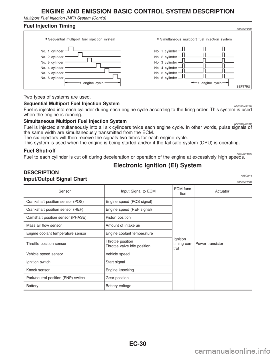
Fuel Injection TimingNBEC0014S07
SEF179U
Two types of systems are used.
Sequential Multiport Fuel Injection System
NBEC0014S0701Fuel is injected into each cylinder during each engine cycle according to the firing order. This system is used
when the engine is running.
Simultaneous Multiport Fuel Injection System
NBEC0014S0702Fuel is injected simultaneously into all six cylinders twice each engine cycle. In other words, pulse signals of
the same width are simultaneously transmitted from the ECM.
The six injectors will then receive the signals two times for each engine cycle.
This system is used when the engine is being started and/or if the fail-safe system (CPU) is operating.
Fuel Shut-offNBEC0014S08Fuel to each cylinder is cut off during deceleration or operation of the engine at excessively high speeds.
Electronic Ignition (EI) System
DESCRIPTIONNBEC0015Input/Output Signal ChartNBEC0015S01
Sensor Input Signal to ECMECM func-
tionActuator
Crankshaft position sensor (POS) Engine speed (POS signal)
Ignition
timing con-
trolPower transistor Crankshaft position sensor (REF) Engine speed (REF signal)
Camshaft position sensor (PHASE) Piston position
Mass air flow sensor Amount of intake air
Engine coolant temperature sensor Engine coolant temperature
Throttle position sensorThrottle position
Throttle valve idle position
Vehicle speed sensor Vehicle speed
Ignition switch Start signal
Knock sensor Engine knocking
Park/neutral position (PNP) switch Gear position
Battery Battery voltage
ENGINE AND EMISSION BASIC CONTROL SYSTEM DESCRIPTION
Multiport Fuel Injection (MFI) System (Cont'd)
EC-30
Page 566 of 2395
System DescriptionNBEC0015S02
SEF742M
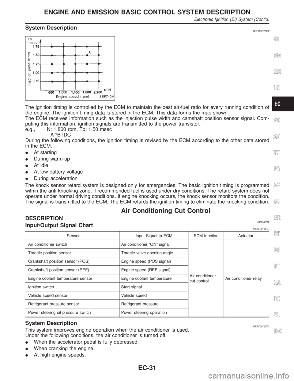
The ignition timing is controlled by the ECM to maintain the best air-fuel ratio for every running condition of
the engine. The ignition timing data is stored in the ECM. This data forms the map shown.
The ECM receives information such as the injection pulse width and camshaft position sensor signal. Com-
puting this information, ignition signals are transmitted to the power transistor.
e.g., N: 1,800 rpm, Tp: 1.50 msec
A ÉBTDC
During the following conditions, the ignition timing is revised by the ECM according to the other data stored
in the ECM.
IAt starting
IDuring warm-up
IAt idle
IAt low battery voltage
IDuring acceleration
The knock sensor retard system is designed only for emergencies. The basic ignition timing is programmed
within the anti-knocking zone, if recommended fuel is used under dry conditions. The retard system does not
operate under normal driving conditions. If engine knocking occurs, the knock sensor monitors the condition.
The signal is transmitted to the ECM. The ECM retards the ignition timing to eliminate the knocking condition.
Air Conditioning Cut Control
DESCRIPTIONNBEC0016Input/Output Signal ChartNBEC0016S01
Sensor Input Signal to ECM ECM function Actuator
Air conditioner switch Air conditioner ªONº signal
Air conditioner
cut controlAir conditioner relay Throttle position sensor Throttle valve opening angle
Crankshaft position sensor (POS) Engine speed (POS signal)
Crankshaft position sensor (REF) Engine speed (REF signal)
Engine coolant temperature sensor Engine coolant temperature
Ignition switch Start signal
Vehicle speed sensor Vehicle speed
Refrigerant pressure sensor Refrigerant pressure
Power steering oil pressure switch Power steering operation
System DescriptionNBEC0016S02This system improves engine operation when the air conditioner is used.
Under the following conditions, the air conditioner is turned off.
IWhen the accelerator pedal is fully depressed.
IWhen cranking the engine.
IAt high engine speeds.
GI
MA
EM
LC
FE
AT
TF
PD
AX
SU
BR
ST
RS
BT
HA
SC
EL
IDX
ENGINE AND EMISSION BASIC CONTROL SYSTEM DESCRIPTION
Electronic Ignition (EI) System (Cont'd)
EC-31
Page 623 of 2395
![INFINITI QX4 2001 Factory Service Manual Monitored item [Unit]ECM
input
signalsMain
signalsDescription Remarks
INT/A TEMP SE
[ÉC] or [ÉF]qqIThe intake air temperature determined
by the signal voltage of the intake air
temperature sensor is INFINITI QX4 2001 Factory Service Manual Monitored item [Unit]ECM
input
signalsMain
signalsDescription Remarks
INT/A TEMP SE
[ÉC] or [ÉF]qqIThe intake air temperature determined
by the signal voltage of the intake air
temperature sensor is](/img/42/57027/w960_57027-622.png)
Monitored item [Unit]ECM
input
signalsMain
signalsDescription Remarks
INT/A TEMP SE
[ÉC] or [ÉF]qqIThe intake air temperature determined
by the signal voltage of the intake air
temperature sensor is indicated.
EVAP SYS PRES [V]qIThe signal voltage of EVAP control sys-
tem pressure sensor is displayed.
ABSOL PRES/SE [V]qIThe signal voltage of the absolute pres-
sure sensor is displayed.
FUEL LEVEL SE [V]qIThe signal voltage of the fuel level sen-
sor is displayed.
START SIGNAL
[ON/OFF]qqIIndicates [ON/OFF] condition from the
starter signal.IAfter starting the engine, [OFF] is dis-
played regardless of the starter signal.
CLSD THL POS
[ON/OFF]qqIIndicates idle position [ON/OFF] com-
puted by ECM according to the throttle
position sensor signal.
CLSD THL/P SW
[ON/OFF]qIIndicates mechanical contact [ON/OFF]
condition of the closed throttle position
switch.
AIR COND SIG
[ON/OFF]qqIIndicates [ON/OFF] condition of the air
conditioner switch as determined by the
air conditioner signal.
P/N POSI SW
[ON/OFF]qqIIndicates [ON/OFF] condition from the
park/neutral position (PNP) switch sig-
nal.
PW/ST SIGNAL
[ON/OFF]qqI[ON/OFF] condition of the power steer-
ing oil pressure switch determined by
the power steering oil pressure signal is
indicated.
LOAD SIGNAL
[ON/OFF]qqIIndicates [ON/OFF] condition from the
electrical load signal and/or lighting
switch.
ON ... rear defogger is operating and/or
lighting switch is on.
OFF ... rear defogger is not operating
and lighting switch is not on.
IGNITION SW
[ON/OFF]qIIndicates [ON/OFF] condition from igni-
tion switch.
SWRL CONT S/V
[ON/OFF]qIThe control condition of the swirl con-
trol valve control solenoid valve (deter-
mined by ECM according to the input
signals) is indicated.
ION ... Swirl control valve is closed.
OFF ... Swirl control valve is opened.
INJ PULSE-B1
[msec]q
IIndicates the actual fuel injection pulse
width compensated by ECM according
to the input signals.IWhen the engine is stopped, a certain
computed value is indicated.
INJ PULSE-B2
[msec]
B/FUEL SCHDL
[msec]qIªBase fuel scheduleº indicates the fuel
injection pulse width programmed into
ECM, prior to any learned on board
correction.
ON BOARD DIAGNOSTIC SYSTEM DESCRIPTION
CONSULT-II (Cont'd)
EC-88
Page 625 of 2395
![INFINITI QX4 2001 Factory Service Manual Monitored item [Unit]ECM
input
signalsMain
signalsDescription Remarks
INT/V TIM (B1) [ÉCA]
IIndicate [ÉCA] of intake camshaft
advanced angle.
INT/V TIM (B2) [ÉCA]
INT/V SOL (B1) [%]IThe control con INFINITI QX4 2001 Factory Service Manual Monitored item [Unit]ECM
input
signalsMain
signalsDescription Remarks
INT/V TIM (B1) [ÉCA]
IIndicate [ÉCA] of intake camshaft
advanced angle.
INT/V TIM (B2) [ÉCA]
INT/V SOL (B1) [%]IThe control con](/img/42/57027/w960_57027-624.png)
Monitored item [Unit]ECM
input
signalsMain
signalsDescription Remarks
INT/V TIM (B1) [ÉCA]
IIndicate [ÉCA] of intake camshaft
advanced angle.
INT/V TIM (B2) [ÉCA]
INT/V SOL (B1) [%]IThe control condition of the intake
valve timing control solenoid valve is
indicated. INT/V SOL (B2) [%]
TRVL AFTER MIL
[km] or [Mile]IDistance traveled while MIL is activated
VIAS S/V
[ON/OFF]IThe control condition of the VIAS con-
trol solenoid valve (determined by ECM
according to the input signal) is indi-
cated.
IOFF ... VIAS control solenoid valve is
not operating.
ON ... VIAS control solenoid valve is
operating.
SWL CON VC SWIIndicates [ON/OFF] condition from the
swirl control valve control vacuum
check switch.
ON ... Swirl control valve is not opera-
tional.
OFF ... Swirl control valve is opera-
tional.
IDL A/V LEANIDisplay the condition of idle air volume
learning
YET ... Idle air volume learning has not
been performed yet.
CMPLT ... Idle air volume learning has
already been performed successfully.
INCMP ... Idle air volume learning has
not been performed successfully.
Voltage [V]IVoltage measured by the voltage
probe.
Frequency
[msec] or [Hz] or [%]IPulse width, frequency or duty cycle
measured by the pulse probe.IOnly ª#º is displayed if item is unable to
be measured.
IFigures with ª#ºs are temporary ones.
They are the same figures as an actual
piece of data which was just previously
measured.
NOTE:
IAny monitored item that does not match the vehicle being diagnosed is deleted from the display automatically.
IRegarding R50 model, ª-B1º indicates right bank and ª-B2º indicates left bank.
IBank 1 (-B1 or BK1) includes No. 1 cylinder.
DATA MONITOR (SPEC) MODENBEC0034S11
Monitored item [Unit]ECM
input
signalsMain
signalsDescription Remarks
MAS A/F SE-B1 [V]qqIThe signal voltage of the mass air flow sen-
sor specification is displayed.IWhen the engine is running, specifi-
cation range is indicated.
B/FUEL SCHDL
[msec]IªBase fuel scheduleº indicates the fuel injec-
tion pulse width programmed into ECM,
prior to any learned on board correction.IWhen the engine is running, specifi-
cation range is indicated.
ON BOARD DIAGNOSTIC SYSTEM DESCRIPTION
CONSULT-II (Cont'd)
EC-90
Page 671 of 2395
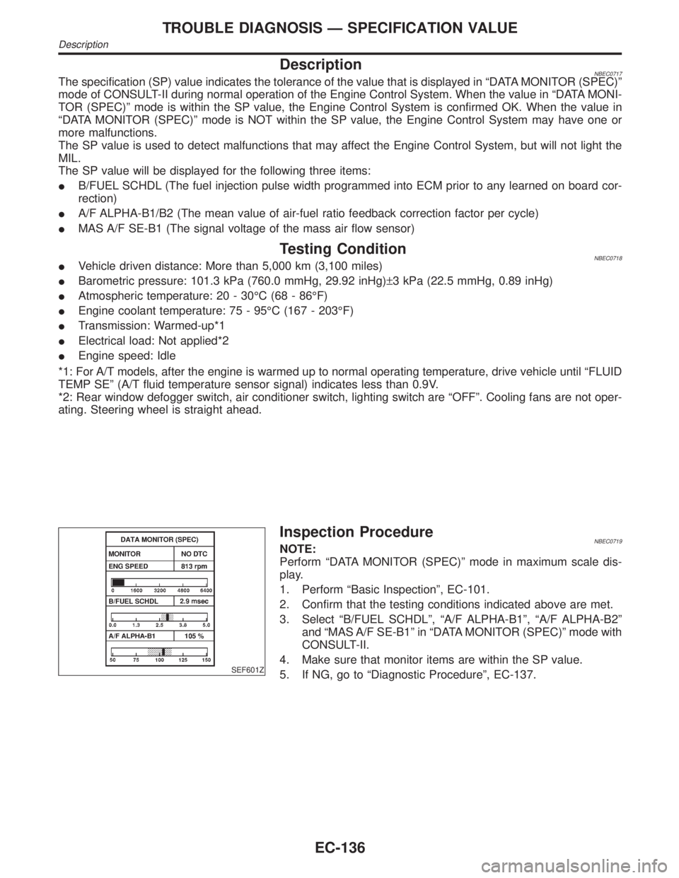
DescriptionNBEC0717The specification (SP) value indicates the tolerance of the value that is displayed in ªDATA MONITOR (SPEC)º
mode of CONSULT-II during normal operation of the Engine Control System. When the value in ªDATA MONI-
TOR (SPEC)º mode is within the SP value, the Engine Control System is confirmed OK. When the value in
ªDATA MONITOR (SPEC)º mode is NOT within the SP value, the Engine Control System may have one or
more malfunctions.
The SP value is used to detect malfunctions that may affect the Engine Control System, but will not light the
MIL.
The SP value will be displayed for the following three items:
IB/FUEL SCHDL (The fuel injection pulse width programmed into ECM prior to any learned on board cor-
rection)
IA/F ALPHA-B1/B2 (The mean value of air-fuel ratio feedback correction factor per cycle)
IMAS A/F SE-B1 (The signal voltage of the mass air flow sensor)
Testing ConditionNBEC0718IVehicle driven distance: More than 5,000 km (3,100 miles)
IBarometric pressure: 101.3 kPa (760.0 mmHg, 29.92 inHg)±3 kPa (22.5 mmHg, 0.89 inHg)
IAtmospheric temperature: 20 - 30ÉC (68 - 86ÉF)
IEngine coolant temperature: 75 - 95ÉC (167 - 203ÉF)
ITransmission: Warmed-up*1
IElectrical load: Not applied*2
IEngine speed: Idle
*1: For A/T models, after the engine is warmed up to normal operating temperature, drive vehicle until ªFLUID
TEMP SEº (A/T fluid temperature sensor signal) indicates less than 0.9V.
*2: Rear window defogger switch, air conditioner switch, lighting switch are ªOFFº. Cooling fans are not oper-
ating. Steering wheel is straight ahead.
SEF601Z
Inspection ProcedureNBEC0719NOTE:
Perform ªDATA MONITOR (SPEC)º mode in maximum scale dis-
play.
1. Perform ªBasic Inspectionº, EC-101.
2. Confirm that the testing conditions indicated above are met.
3. Select ªB/FUEL SCHDLº, ªA/F ALPHA-B1º, ªA/F ALPHA-B2º
and ªMAS A/F SE-B1º in ªDATA MONITOR (SPEC)º mode with
CONSULT-II.
4. Make sure that monitor items are within the SP value.
5. If NG, go to ªDiagnostic Procedureº, EC-137.
TROUBLE DIAGNOSIS Ð SPECIFICATION VALUE
Description
EC-136
Page 986 of 2395
SEF354Z
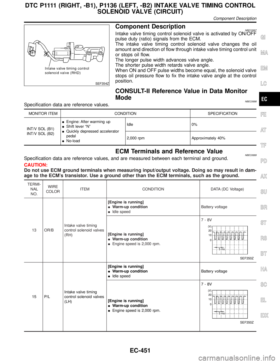
Component DescriptionNBEC0697Intake valve timing control solenoid valve is activated by ON/OFF
pulse duty (ratio) signals from the ECM.
The intake valve timing control solenoid valve changes the oil
amount and direction of flow through intake valve timing control unit
or stops oil flow.
The longer pulse width advances valve angle.
The shorter pulse width retards valve angle.
When ON and OFF pulse widths become equal, the solenoid valve
stops oil pressure flow to fix the intake valve angle at the control
position.
CONSULT-II Reference Value in Data Monitor
Mode
NBEC0698Specification data are reference values.
MONITOR ITEM CONDITION SPECIFICATION
INT/V SOL (B1)
INT/V SOL (B2)IEngine: After warming up
IShift lever ªNº
IQuickly depressed accelerator
pedal
INo-loadIdle 0%
2,000 rpm Approximately 40%
ECM Terminals and Reference ValueNBEC0699Specification data are reference values, and are measured between each terminal and ground.
CAUTION:
Do not use ECM ground terminals when measuring input/output voltage. Doing so may result in dam-
age to the ECM's transistor. Use a ground other than the ECM terminals, such as the ground.
TERMI-
NAL
NO.WIRE
COLORITEM CONDITION DATA (DC Voltage)
13 OR/BIntake valve timing
control solenoid valves
(RH)[Engine is running]
IWarm-up condition
IIdle speedBattery voltage
[Engine is running]
IWarm-up condition
IEngine speed is 2,000 rpm.7-8V
SEF350Z
15 P/LIntake valve timing
control solenoid valves
(LH)[Engine is running]
IWarm-up condition
IIdle speedBattery voltage
[Engine is running]
IWarm-up condition
IEngine speed is 2,000 rpm.7-8V
SEF350Z
GI
MA
EM
LC
FE
AT
TF
PD
AX
SU
BR
ST
RS
BT
HA
SC
EL
IDX
D T C P 1111(RIGHT, -B1), P1136 (LEFT, -B2) INTAKE VALVE TIMING CONTROL
SOLENOID VALVE (CIRCUIT)
Component Description
EC-451
Page 1574 of 2395
SEL690V
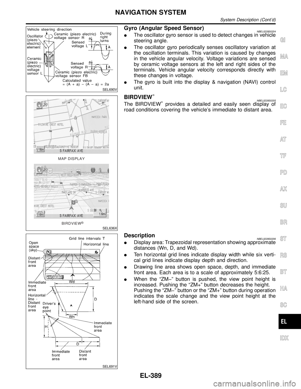
Gyro (Angular Speed Sensor)NBEL0228S0204IThe oscillator gyro sensor is used to detect changes in vehicle
steering angle.
IThe oscillator gyro periodically senses oscillatory variation at
the oscillation terminals. This variation is caused by changes
in the vehicle angular velocity. Voltage variations are sensed
by ceramic voltage sensors at the left and right sides of the
terminals. Vehicle angular velocity corresponds directly with
these changes in voltage.
IThe gyro is built into the display & navigation (NAVI) control
unit.
MAP DISPLAY
BIRDVIEW
R
SEL636X
BIRDVIEWTNBEL0228S0205The BIRDVIEWTprovides a detailed and easily seen display of
road conditions covering the vehicle's immediate to distant area.
SEL691V
DescriptionNBEL0228S0206IDisplay area: Trapezoidal representation showing approximate
distances (Wn, D, and Wd).
ITen horizontal grid lines indicate display width while six verti-
cal grid lines indicate display depth and direction.
IDrawing line area shows open space, depth, and immediate
front area. Each area is to a scale of approximately 5:6:25.
IWhen the ªZMþº button is pushed, the view point height is
increased. Pushing the ªZM+º button decreases the height.
Pushing the ªZMþº button or the ªZM+º button during operation
indicates the scale change and the view point height at the
left-hand side of the screen.
GI
MA
EM
LC
EC
FE
AT
TF
PD
AX
SU
BR
ST
RS
BT
HA
SC
IDX
NAVIGATION SYSTEM
System Description (Cont'd)
EL-389