Crankshaft position INFINITI QX4 2001 Factory User Guide
[x] Cancel search | Manufacturer: INFINITI, Model Year: 2001, Model line: QX4, Model: INFINITI QX4 2001Pages: 2395, PDF Size: 43.2 MB
Page 567 of 2395

IWhen the engine coolant temperature becomes excessively high.
IWhen operating power steering during low engine speed or low vehicle speed.
IWhen engine speed is excessively low.
IWhen refrigerant pressure is excessively low or high.
Fuel Cut Control (at no load & high engine
speed)
DESCRIPTIONNBEC0017Input/Output Signal ChartNBEC0017S01
Sensor Input Signal to ECMECM func-
tionActuator
Vehicle speed sensor Vehicle speed
Fuel cut
controlInjectors Park/neutral position (PNP) switch Neutral position
Throttle position sensor Throttle position
Engine coolant temperature sensor Engine coolant temperature
Crankshaft position sensor (POS) Engine speed (POS signal)
Crankshaft position sensor (REF) Engine speed (REF signal)
If the engine speed is above 1,800 rpm with no load (for example, in neutral and engine speed over 1,800
rpm) fuel will be cut off after some time. The exact time when the fuel is cut off varies based on engine speed.
Fuel cut will operate until the engine speed reaches 1,500 rpm, then fuel cut is cancelled.
NOTE:
This function is different from deceleration control listed under ªMultiport Fuel Injection (MFI) Systemº, EC-28.
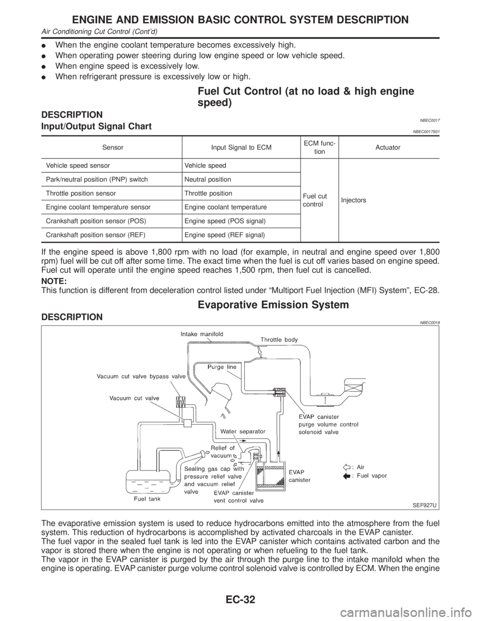
Evaporative Emission System
DESCRIPTIONNBEC0018
SEF927U
The evaporative emission system is used to reduce hydrocarbons emitted into the atmosphere from the fuel
system. This reduction of hydrocarbons is accomplished by activated charcoals in the EVAP canister.
The fuel vapor in the sealed fuel tank is led into the EVAP canister which contains activated carbon and the
vapor is stored there when the engine is not operating or when refueling to the fuel tank.
The vapor in the EVAP canister is purged by the air through the purge line to the intake manifold when the
engine is operating. EVAP canister purge volume control solenoid valve is controlled by ECM. When the engine
ENGINE AND EMISSION BASIC CONTROL SYSTEM DESCRIPTION
Air Conditioning Cut Control (Cont'd)
EC-32
Page 617 of 2395

ENGINE CONTROL COMPONENT PARTS/CONTROL
SYSTEMS APPLICATION
NBEC0034S02
ItemDIAGNOSTIC TEST MODE
WORK
SUP-
PORTSELF-DIAGNOSTIC
RESULTS
D ATA
MONI-
TORD ATA
MONI-
TOR
(SPEC)ACTIVE
TESTDTC & SRT
CONFIRMATION
DTC*1FREEZE
FRAME
DATA*2SRT
STATUSDTC
WORK
SUP-
PORT
ENGINE CONTROL COMPONENT PARTS
INPUT
Crankshaft position sensor
(POS)XXXX
Crankshaft position sensor (REF) X X X
Mass air flow sensor X X X
Engine coolant temperature sen-
sorXXXXX
Heated oxygen sensor 1 (front) X X X X X
Heated oxygen sensor 2 (rear) X X X X X
Vehicle speed sensorXXXX
Throttle position sensor X X X
Fuel tank temperature sensor X X X X
EVAP control system pressure
sensorXXX
Absolute pressure sensor X X X
Intake air temperature sensor X X X
Knock sensor X
Ignition switch (start signal) X X
Closed throttle position switch X X X
Closed throttle position switch
(throttle position sensor signal)XX
Air conditioner switch X X
Park/neutral position (PNP)
switchXXX
Power steering oil pressure
switchXX
Battery voltage X X
Ambient air temperature switch X X
Load signal X X
Swirl control valve control
vacuum check switchXXX
Fuel level sensor X X X
Intake valve timing control posi-
tion sensorXXX
ON BOARD DIAGNOSTIC SYSTEM DESCRIPTION
CONSULT-II (Cont'd)
EC-82
Page 622 of 2395
![INFINITI QX4 2001 Factory User Guide DATA MONITOR MODE=NBEC0034S06
Monitored item [Unit]ECM
input
signalsMain
signalsDescription Remarks
ENG SPEED [rpm]qqIIndicates the engine speed computed
from the REF signal (120É signal) of the
cran INFINITI QX4 2001 Factory User Guide DATA MONITOR MODE=NBEC0034S06
Monitored item [Unit]ECM
input
signalsMain
signalsDescription Remarks
ENG SPEED [rpm]qqIIndicates the engine speed computed
from the REF signal (120É signal) of the
cran](/img/42/57027/w960_57027-621.png)
DATA MONITOR MODE=NBEC0034S06
Monitored item [Unit]ECM
input
signalsMain
signalsDescription Remarks
ENG SPEED [rpm]qqIIndicates the engine speed computed
from the REF signal (120É signal) of the
crankshaft position sensor (REF).
CKPS´RPM (POS)
[rpm]qIIndicates the engine speed computed
from the POS signal (1É signal) of the
crankshaft position sensor (POS).IAccuracy becomes poor if engine
speed drops below the idle rpm.
IIf the signal is interrupted while the
engine is running, an abnormal value
may be indicated.
POS COUNTqIIndicates the number of signal plate
(Flywheel/Drive Plate) cogs (tooth) dur-
ing one revolution of the engine.
MAS A/F SE-B1 [V]qqIThe signal voltage of the mass air flow
sensor is displayed.IWhen the engine is stopped, a certain
value is indicated.
COOLAN TEMP/S
[ÉC] or [ÉF]qqIThe engine coolant temperature (deter-
mined by the signal voltage of the
engine coolant temperature sensor) is
displayed.IWhen the engine coolant temperature
sensor is open or short-circuited, ECM
enters fail-safe mode. The engine cool-
ant temperature determined by the
ECM is displayed.
HO2S1 (B1) [V]qq
IThe signal voltage of the front heated
oxygen sensor is displayed.
HO2S1 (B2) [V]qq
HO2S2 (B1) [V]qq
IThe signal voltage of the rear heated
oxygen sensor is displayed.
HO2S2 (B2) [V]qq
HO2S1 MNTR (B1)
[RICH/LEAN]qIDisplay of front heated oxygen sensor
signal during air-fuel ratio feedback
control:
RICH ... means the mixture became
ªrichº, and control is being affected
toward a leaner mixture.
LEAN ... means the mixture became
ªleanº, and control is being affected
toward a rich mixture.IAfter turning ON the ignition switch,
ªRICHº is displayed until air-fuel mixture
ratio feedback control begins.
IWhen the air-fuel ratio feedback is
clamped, the value just before the
clamping is displayed continuously. HO2S1 MNTR (B2)
[RICH/LEAN]q
HO2S2 MNTR (B1)
[RICH/LEAN]qIDisplay of rear heated oxygen sensor
signal:
RICH ... means the amount of oxygen
after three way catalyst is relatively
small.
LEAN ... means the amount of oxygen
after three way catalyst is relatively
large.IWhen the engine is stopped, a certain
value is indicated.
HO2S2 MNTR (B2)
[RICH/LEAN]q
VHCL SPEED SE
[km/h] or [mph]qqIThe vehicle speed computed from the
vehicle speed sensor signal is dis-
played.
BATTERY VOLT [V]qqIThe power supply voltage of ECM is
displayed.
THRTL POS SEN [V]qqIThe throttle position sensor signal volt-
age is displayed.
FUEL T/TMP SE
[ÉC] or [ÉF]IThe fuel temperature judged from the
tank fuel temperature sensor signal
voltage is displayed.GI
MA
EM
LC
FE
AT
TF
PD
AX
SU
BR
ST
RS
BT
HA
SC
EL
IDX
ON BOARD DIAGNOSTIC SYSTEM DESCRIPTION
CONSULT-II (Cont'd)
EC-87
Page 651 of 2395

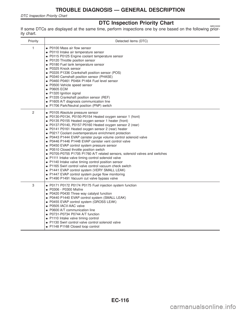
DTC Inspection Priority ChartNBEC0039If some DTCs are displayed at the same time, perform inspections one by one based on the following prior-
ity chart.
Priority Detected items (DTC)
1IP0100 Mass air flow sensor
IP0110 Intake air temperature sensor
IP0115 P0125 Engine coolant temperature sensor
IP0120 Throttle position sensor
IP0180 Fuel tank temperature sensor
IP0325 Knock sensor
IP0335 P1336 Crankshaft position sensor (POS)
IP0340 Camshaft position sensor (PHASE)
IP0460 P0461 P0464 P1464 Fuel level sensor
IP0500 Vehicle speed sensor
IP0605 ECM
IP1320 Ignition signal
IP1335 Crankshaft position sensor (REF)
IP1605 A/T diagnosis communication line
IP1706 Park/Neutral position (PNP) switch
2IP0105 Absolute pressure sensor
IP0130-P0134, P0150-P0154 Heated oxygen sensor 1 (front)
IP0135 P0155 Heated oxygen sensor 1 heater (front)
IP0137-P0140, P0157-P0160 Heated oxygen sensor 2 (rear)
IP0141 P0161 Heated oxygen sensor 2 (rear) heater
IP0217 Coolant overtemperature enrichment protection
IP0443 P1444 EVAP canister purge volume control solenoid valve
IP0446 P1446 P1448 EVAP canister vent control valve
IP0450 EVAP control system pressure sensor
IP0510 Closed throttle position switch
IP0705-P0755 P1705 P1760 A/T related sensors, solenoid valves and switches
IP 1111Intake valve timing control solenoid valve
IP1140 Intake valve timing control position sensor
IP1165 Swirl control valve control vacuum check switch
IP1441 EVAP control system (VERY SMALL LEAK)
IP1447 EVAP control system purge flow monitoring
IP1490 P1491 Vacuum cut valve bypass valve
3IP0171 P0172 P0174 P0175 Fuel injection system function
IP0306 - P0300 Misfire
IP0420 P0430 Three way catalyst function
IP0440 P1440 EVAP control system (SMALL LEAK)
IP0455 EVAP control system (GROSS LEAK)
IP0505 IACV-AAC valve
IP0600 A/T communication line
IP0731-P0734 P0744 A/T function
IP1110 Intake valve timing control
IP1130 Swirl control valve control solenoid valve
IP1148 P1168 Closed loop control
TROUBLE DIAGNOSIS Ð GENERAL DESCRIPTION
DTC Inspection Priority Chart
EC-116
Page 652 of 2395

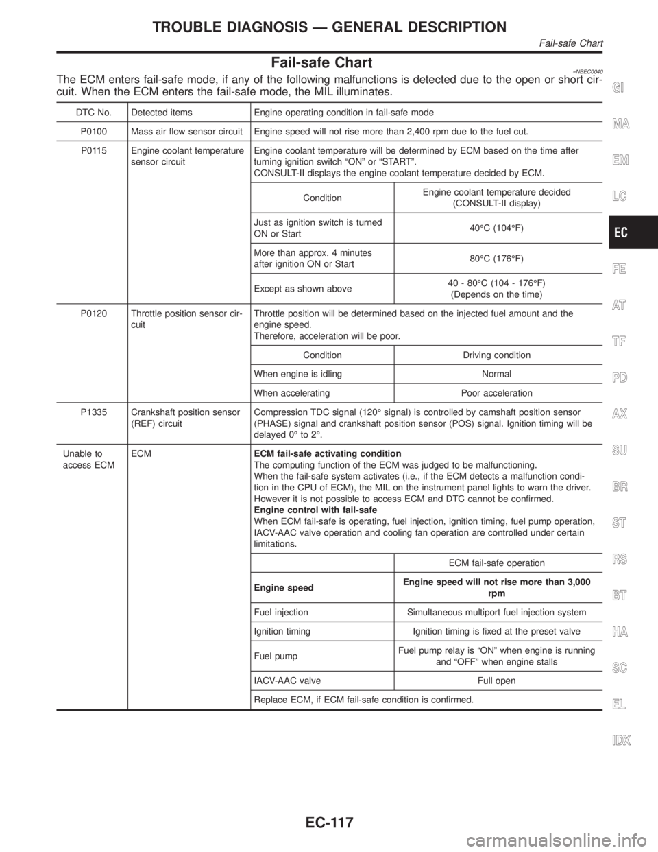
Fail-safe Chart=NBEC0040The ECM enters fail-safe mode, if any of the following malfunctions is detected due to the open or short cir-
cuit. When the ECM enters the fail-safe mode, the MIL illuminates.
DTC No. Detected items Engine operating condition in fail-safe mode
P0100 Mass air flow sensor circuit Engine speed will not rise more than 2,400 rpm due to the fuel cut.
P0115 Engine coolant temperature
sensor circuitEngine coolant temperature will be determined by ECM based on the time after
turning ignition switch ªONº or ªSTARTº.
CONSULT-II displays the engine coolant temperature decided by ECM.
ConditionEngine coolant temperature decided
(CONSULT-II display)
Just as ignition switch is turned
ON or Start40ÉC (104ÉF)
More than approx. 4 minutes
after ignition ON or Start80ÉC (176ÉF)
Except as shown above40 - 80ÉC (104 - 176ÉF)
(Depends on the time)
P0120 Throttle position sensor cir-
cuitThrottle position will be determined based on the injected fuel amount and the
engine speed.
Therefore, acceleration will be poor.
Condition Driving condition
When engine is idling Normal
When accelerating Poor acceleration
P1335 Crankshaft position sensor
(REF) circuitCompression TDC signal (120É signal) is controlled by camshaft position sensor
(PHASE) signal and crankshaft position sensor (POS) signal. Ignition timing will be
delayed 0É to 2É.
Unable to
access ECMECMECM fail-safe activating condition
The computing function of the ECM was judged to be malfunctioning.
When the fail-safe system activates (i.e., if the ECM detects a malfunction condi-
tion in the CPU of ECM), the MIL on the instrument panel lights to warn the driver.
However it is not possible to access ECM and DTC cannot be confirmed.
Engine control with fail-safe
When ECM fail-safe is operating, fuel injection, ignition timing, fuel pump operation,
IACV-AAC valve operation and cooling fan operation are controlled under certain
limitations.
ECM fail-safe operation
Engine speedEngine speed will not rise more than 3,000
rpm
Fuel injection Simultaneous multiport fuel injection system
Ignition timing Ignition timing is fixed at the preset valve
Fuel pumpFuel pump relay is ªONº when engine is running
and ªOFFº when engine stalls
IACV-AAC valve Full open
Replace ECM, if ECM fail-safe condition is confirmed.
GI
MA
EM
LC
FE
AT
TF
PD
AX
SU
BR
ST
RS
BT
HA
SC
EL
IDX
TROUBLE DIAGNOSIS Ð GENERAL DESCRIPTION
Fail-safe Chart
EC-117
Page 654 of 2395

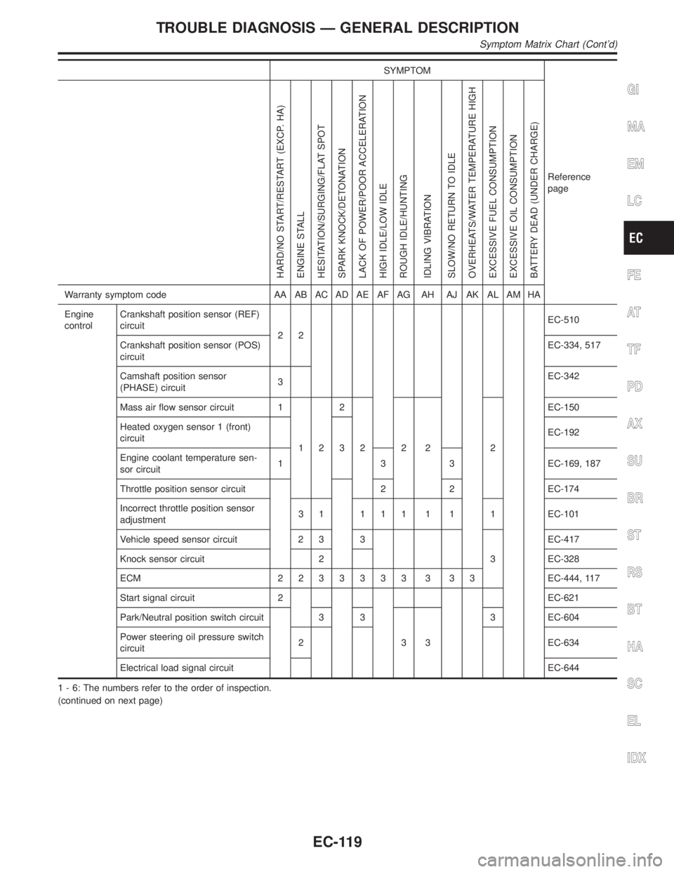
SYMPTOM
Reference
page
HARD/NO START/RESTART (EXCP. HA)
ENGINE STALL
HESITATION/SURGING/FLAT SPOT
SPARK KNOCK/DETONATION
LACK OF POWER/POOR ACCELERATION
HIGH IDLE/LOW IDLE
ROUGH IDLE/HUNTING
IDLING VIBRATION
SLOW/NO RETURN TO IDLE
OVERHEATS/WATER TEMPERATURE HIGH
EXCESSIVE FUEL CONSUMPTION
EXCESSIVE OIL CONSUMPTION
BATTERY DEAD (UNDER CHARGE)
Warranty symptom code AA AB AC AD AE AF AG AH AJ AK AL AM HA
Engine
controlCrankshaft position sensor (REF)
circuit
22EC-510
Crankshaft position sensor (POS)
circuitEC-334, 517
Camshaft position sensor
(PHASE) circuit3EC-342
Mass air flow sensor circuit 1
122
222 2EC-150
Heated oxygen sensor 1 (front)
circuit
3EC-192
Engine coolant temperature sen-
sor circuit1 3 3 EC-169, 187
Throttle position sensor circuit 2 2 EC-174
Incorrect throttle position sensor
adjustment3 1 1 1 1 1 1 1 EC-101
Vehicle speed sensor circuit 2 3 3
3EC-417
Knock sensor circuit 2 EC-328
ECM 2233333 3 33EC-444, 117
Start signal circuit 2 EC-621
Park/Neutral position switch circuit 3 3
333 EC-604
Power steering oil pressure switch
circuit2 EC-634
Electrical load signal circuitEC-644
1 - 6: The numbers refer to the order of inspection.
(continued on next page)
GI
MA
EM
LC
FE
AT
TF
PD
AX
SU
BR
ST
RS
BT
HA
SC
EL
IDX
TROUBLE DIAGNOSIS Ð GENERAL DESCRIPTION
Symptom Matrix Chart (Cont'd)
EC-119
Page 667 of 2395
![INFINITI QX4 2001 Factory User Guide TERMI-
NAL
NO.WIRE
COLORITEM CONDITION DATA (DC Voltage)
61 OR Mass air flow sensor[Engine is running]
IWarm-up condition
IIdle speed1.2 - 1.8V
[Engine is running]
IWarm-up condition
IEngine speed is INFINITI QX4 2001 Factory User Guide TERMI-
NAL
NO.WIRE
COLORITEM CONDITION DATA (DC Voltage)
61 OR Mass air flow sensor[Engine is running]
IWarm-up condition
IIdle speed1.2 - 1.8V
[Engine is running]
IWarm-up condition
IEngine speed is](/img/42/57027/w960_57027-666.png)
TERMI-
NAL
NO.WIRE
COLORITEM CONDITION DATA (DC Voltage)
61 OR Mass air flow sensor[Engine is running]
IWarm-up condition
IIdle speed1.2 - 1.8V
[Engine is running]
IWarm-up condition
IEngine speed is 2,500 rpm.1.6 - 2.2V
62 G/BHeated oxygen sensor
1 (front) (bank 2)[Engine is running]
IWarm-up condition
IEngine speed is 2,000 rpm.0 - Approximately 1.0V (Peri-
odically change)
SEF059V
63 GHeated oxygen sensor
1 (front) (bank 1)[Engine is running]
IWarm-up condition
IEngine speed is 2,000 rpm.0 - Approximately 1.0V (Peri-
odically change)
SEF059V
64 Y/PUIntake air temperature
sensor[Engine is running]Approximately 0 - 4.8V
Output voltage varies with
intake air temperature.
65
75LG
LGCrankshaft position
sensor (REF)[Engine is running]
IWarm-up condition
IIdle speedApproximately 2.3VH
(AC voltage)
SEF581X
66
76L
LCamshaft position sen-
sor (PHASE)[Engine is running]
IWarm-up condition
IIdle speedApproximately 4.2VH
(AC voltage)
SEF582X
12
67W/RPower supply for ECM
(Buck-up)[Ignition switch ªOFFº]BATTERY VOLTAGE
(11 - 14V)
70 LG/REngine coolant tem-
perature sensor[Engine is running]Approximately 0 - 4.8V
Output voltage varies with
engine coolant temperature.
TROUBLE DIAGNOSIS Ð GENERAL DESCRIPTION
ECM Terminals and Reference Value (Cont'd)
EC-132
Page 669 of 2395
![INFINITI QX4 2001 Factory User Guide TERMI-
NAL
NO.WIRE
COLORITEM CONDITION DATA (DC Voltage)
85 YCrankshaft position
sensor (POS)[Engine is running]
IIdle speedApproximately 2.4V
SEF057V
[Engine is running]
IEngine speed is 2,000 rpm.Ap INFINITI QX4 2001 Factory User Guide TERMI-
NAL
NO.WIRE
COLORITEM CONDITION DATA (DC Voltage)
85 YCrankshaft position
sensor (POS)[Engine is running]
IIdle speedApproximately 2.4V
SEF057V
[Engine is running]
IEngine speed is 2,000 rpm.Ap](/img/42/57027/w960_57027-668.png)
TERMI-
NAL
NO.WIRE
COLORITEM CONDITION DATA (DC Voltage)
85 YCrankshaft position
sensor (POS)[Engine is running]
IIdle speedApproximately 2.4V
SEF057V
[Engine is running]
IEngine speed is 2,000 rpm.Approximately 2.3V
SEF058V
86 W/L Vehicle speed sensor[Engine is running]
IJack up front wheels.
IIn 1st gear position
I10 km/h (6 MPH)Approximately 2.5VSEF583X
[Engine is running]
IJack up front wheels.
IIn 2nd gear position
I30 km/h (19 MPH)Approximately 2.0V
SEF584X
89 ORIntake valve timing
control position sen-
sors (LH)[Engine is running]
IWarm-up condition
IIdle speedApproximatley 0.5VSEF351Z
[Engine is running]
IWarm-up condition
IEngine speed is 2,000 rpm.Approximatley 0.5V
SEF352Z
TROUBLE DIAGNOSIS Ð GENERAL DESCRIPTION
ECM Terminals and Reference Value (Cont'd)
EC-134
Page 711 of 2395

ICrankshaft position sensor (REF)
ICrankshaft position sensor (POS)
IMass air flow sensor
MALFUNCTION CNBEC0430S03IHarness or connectors
(The throttle position sensor circuit is open or shorted.)
IIntake air leaks
IThrottle position sensor
DTC Confirmation ProcedureNBEC0078NOTE:
IPerform ªPROCEDURE FOR MALFUNCTION Aº first. If the
1st trip DTC cannot be confirmed, perform ªPROCEDURE
FOR MALFUNCTION Bº.
If there is no problem on ªPROCEDURE FOR MALFUNC-
TION Bº, perform ªPROCEDURE FOR MALFUNCTION Cº.
IIf ªDTC Confirmation Procedureº has been previously
conducted, always turn ignition switch ªOFFº and wait at least
10 seconds before conducting the next test.
PROCEDURE FOR MALFUNCTION ANBEC0078S01CAUTION:
Always drive vehicle at a safe speed.
TESTING CONDITION:
IBefore performing the following procedure, confirm that
battery voltage is more than 10V at idle.
IThis test may be conducted with the drive wheels lifted in
the shop or by driving the vehicle. If a road test is
expected to be easier, it is unnecessary to lift the vehicle.
SEF065Y
With CONSULT-IINBEC0078S01011) Turn ignition switch ªONº and select ªDATA MONITORº mode
with CONSULT-II.
2) Start engine and maintain the following conditions for at least
5 consecutive seconds.
Vehicle speed More than 5 km/h (3 MPH)
Selector lever Suitable position except ªPº or ªNº position
3) If 1st trip DTC is detected, go to ªDiagnostic Procedureº,
EC-181.
With GSTNBEC0078S0102Follow the procedure ªWith CONSULT-IIº above.
DTC P0120 THROTTLE POSITION SENSOR
Possible Cause (Cont'd)
EC-176
Page 720 of 2395

12 CHECK MASS AIR FLOW SENSOR
1. Reconnect harness connectors disconneted.
2. Start engine and warm it up to normal operating temperature.
3. Check voltage between ECM terminal 61 (Mass air flow sensor signal) and ground.
SEF298X
4. If the voltage is out of specification, disconnect mass air flow sensor harness connector and connect it again.
Then repeat above check.
OK or NG
OK©GO TO 13.
NG©Replace mass air flow sensor.
13 CHECK CRANKSHAFT POSITION SENSOR (POS)
1. Install all removed parts.
2. Perform ªDTC Confirmation Procedureº for DTC P0335 and P1336. Refer to EC-336, 519.
OK or NG
OK©GO TO 14.
NG©Replace crankshaft position sensor (POS).
14 CHECK CRANKSHAFT POSITION SENSOR (REF)
Perform ªDTC Confirmation Procedureº for DTC P1335. Refer to EC-511.
OK or NG
OK©GO TO 15.
NG©Replace crankshaft position sensor (REF).
GI
MA
EM
LC
FE
AT
TF
PD
AX
SU
BR
ST
RS
BT
HA
SC
EL
IDX
DTC P0120 THROTTLE POSITION SENSOR
Diagnostic Procedure (Cont'd)
EC-185