display INFINITI QX4 2001 Factory Service Manual
[x] Cancel search | Manufacturer: INFINITI, Model Year: 2001, Model line: QX4, Model: INFINITI QX4 2001Pages: 2395, PDF Size: 43.2 MB
Page 5 of 2395

Attachment No.14
TID CID
P0420 01H 01H Max. X -
P0420 02H 81H Min. X -
P0430 03H 02H Max. X -
P0430 04H 82H Min. X -
P0440 05H 03H Max. X -
P1440
★1 05H 03H Max. X -
EVAP control system purge flow monitoring P1447 06H 83H Min. X mV
EVAP control system (Very small leak) P1441
★2 07H 03H Max. X -
P0133 09H 04H Max. X ms
P0131 0AH 84H Min. X mV
P0130 0BH 04H Max. X mV
P0132 0CH 04H Max. X mV
P0134 0DH 04H Max. X s
P0153 11H 05H Max. X ms
P0151 12H 85H Min. X mV
P0150 13H 05H Max. X mV
P0152 14H 05H Max. X mV
P0154 15H 05H Max. X s
P0139 19H 86H Min. X mV/500ms
P0137 1AH 86H Min. X mV
P0140 1BH 06H Max. X mV
P0138 1CH 06H Max. X mV
P0159 21H 87H Min. X mV/500ms
P0157 22H 87H Min. X mV
P0160 23H 07H Max. X mV
P0158 24H 07H Max. X mV
P0135 29H 08H Max. X mV
P0135 2AH 88H Min. X mV
P0155 2BH 09H Max. X mV
P0155 2CH 89H Min. X mV
P0141 2DH 0AH Max. X mV
P0141 2EH 8AH Min. X mV
P0161 2FH 0BH Max. X mV
P0161 30H 8BH Min. X mV
TEST VALUE AND TEST LIMIT (GST ONLY — NOT APPLICABLE TO CONSULT-II)
The following is the information specified in Mode 6 of SAE J1979.
The test value is a parameter used to determine whether a system/circuit diagnostic test is “OK” or “NG” while
being monitored by the ECM during self-diagnosis. The test limit is a reference value which is specified as the
maximum or minimum value and is compared with the test value being monitored.
Items for which these data (test value and test limit) are displayed are the same as SRT code items.
These data (test value and test limit) are specified by Test ID (TID) and Component ID (CID) and can be dis-
played on the GST screen.
: Applicable ・: Not applicable
SRT item Self-diagnostic test item DTCTest value
(GST display)Te s t limit Application Unit
CATALYSTThree way catalyst function (Bank 1)
Three way catalyst function (Bank 2)
EVAP SYSTEMEVAP control system (Small leak)
HO2SHeated oxygen sensor 1(Bank 1)
Heated oxygen sensor 1(Bank 2)
Heated oxygen sensor 2(Bank 1)
Heated oxygen sensor 2(Bank 2)
HO2S HTRHeated oxygen sensor 1 heater(Bank 1)
Heated oxygen sensor 2 heater(Bank 2)
Heated oxygen sensor 2 heater(Bank 1)
Heated oxygen sensor 2 heater(Bank 2)
★<021103d60225025802430245025002540200024d024f02440245024c0253020002240212021202000236022702130213022502000245024e02470249024e0245020c0200023702240212021202000236022702130213022502000245024e02470249024e02
45020c02000232021502100200023602310213021502240225> engine, JR50 VQ35DE engine 2001★<021203d60225025802430245025002540200024d024f02440245024c02530200022102130213020002360231021302100224022502000245024e02470249024e0245020c02000223022102130213020002360231021302100224022502000245024e024702
49024e024502000212021002100211022d0239020e>
Page 12 of 2395
SEF291H
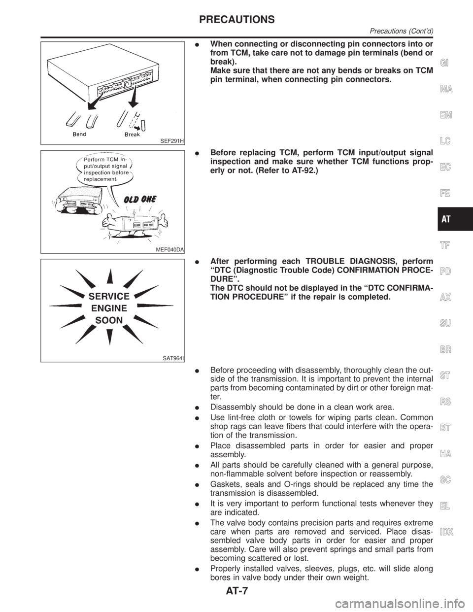
IWhen connecting or disconnecting pin connectors into or
from TCM, take care not to damage pin terminals (bend or
break).
Make sure that there are not any bends or breaks on TCM
pin terminal, when connecting pin connectors.
MEF040DA
IBefore replacing TCM, perform TCM input/output signal
inspection and make sure whether TCM functions prop-
erly or not. (Refer to AT-92.)
SAT964I
IAfter performing each TROUBLE DIAGNOSIS, perform
ªDTC (Diagnostic Trouble Code) CONFIRMATION PROCE-
DUREº.
The DTC should not be displayed in the ªDTC CONFIRMA-
TION PROCEDUREº if the repair is completed.
IBefore proceeding with disassembly, thoroughly clean the out-
side of the transmission. It is important to prevent the internal
parts from becoming contaminated by dirt or other foreign mat-
ter.
IDisassembly should be done in a clean work area.
IUse lint-free cloth or towels for wiping parts clean. Common
shop rags can leave fibers that could interfere with the opera-
tion of the transmission.
IPlace disassembled parts in order for easier and proper
assembly.
IAll parts should be carefully cleaned with a general purpose,
non-flammable solvent before inspection or reassembly.
IGaskets, seals and O-rings should be replaced any time the
transmission is disassembled.
IIt is very important to perform functional tests whenever they
are indicated.
IThe valve body contains precision parts and requires extreme
care when parts are removed and serviced. Place disas-
sembled valve body parts in order for easier and proper
assembly. Care will also prevent springs and small parts from
becoming scattered or lost.
IProperly installed valves, sleeves, plugs, etc. will slide along
bores in valve body under their own weight.
GI
MA
EM
LC
EC
FE
TF
PD
AX
SU
BR
ST
RS
BT
HA
SC
EL
IDX
PRECAUTIONS
Precautions (Cont'd)
AT-7
Page 14 of 2395
IThe threads in one or more of the converter bolt holes are damaged.
ITransmission failure did not display evidence of damaged or worn internal parts, steel particles or clutch
plate lining material in unit and inside the fluid filter.
IVehicle has been exposed to high mileage (only). The exception may be where the torque converter clutch
dampener plate lining has seen excess wear by vehicles operated in heavy and/or constant traffic, such
as taxi, delivery or police use.
ATF COOLER SERVICENBAT0004S02Replace ATF cooler if excessive foreign material is found in oil pan or clogging strainer.
Replace radiator lower tank (which includes ATF cooler) with a new one and flush cooler line using cleaning
solvent and compressed air. Refer to LC-19, ªREMOVAL AND INSTALLATIONº.
OBD-II SELF-DIAGNOSISNBAT0004S03IA/T self-diagnosis is performed by the TCM in combination with the ECM. The results can be read through
the blinking pattern of the O/D OFF indicator or the malfunction indicator lamp (MIL). Refer to the table on
AT-38 for the indicator used to display each self-diagnostic result.
IThe self-diagnostic results indicated by the MIL are automatically stored in both the ECM and TCM
memories.
Always perform the procedure ªHOW TO ERASE DTCº on AT-35 to complete the repair and avoid
unnecessary blinking of the MIL.
IThe following self-diagnostic items can be detected using ECM self-diagnostic results mode* only when
the O/D OFF indicator lamp does not indicate any malfunctions.
þ PNP switch
þ A/T 1st, 2nd, 3rd, or 4th gear function
þ A/T TCC S/V function (lock-up)
*: For details of OBD-II, refer to EC-59, ªIntroductionº.
ICertain systems and components, especially those related to OBD, may use the new style slide-
locking type harness connector. For description and how to disconnect, refer to EL-5, ªDescrip-
tionº.
Wiring Diagrams and Trouble DiagnosisNBAT0005When you read wiring diagrams, refer to the following:
IGI-11, ªHOW TO READ WIRING DIAGRAMSº.
IEL-9, ªPOWER SUPPLY ROUTINGº for power distribution circuit.
When you perform trouble diagnosis, refer to the following:
IGI-35, ªHOW TO FOLLOW TEST GROUP IN TROUBLE DIAGNOSISº.
IGI-24, ªHOW TO PERFORM EFFICIENT DIAGNOSIS FOR AN ELECTRICAL INCIDENTº.
GI
MA
EM
LC
EC
FE
TF
PD
AX
SU
BR
ST
RS
BT
HA
SC
EL
IDX
PRECAUTIONS
Service Notice or Precautions (Cont'd)
AT-9
Page 38 of 2395
IntroductionNBAT0014The A/T system has two self-diagnostic systems.
The first is the emission-related on board diagnostic system (OBD-II) performed by the TCM in combination
with the ECM. The malfunction is indicated by the MIL (malfunction indicator lamp) and is stored as a DTC in
the ECM memory but not the TCM memory.
The second is the TCM original self-diagnosis indicated by the O/D OFF indicator lamp. The malfunction is
stored in the TCM memory. The detected items are overlapped with OBD-II self-diagnostic items. For detail,
refer to AT-38.
OBD-II Function for A/T SystemNBAT0182The ECM provides emission-related on board diagnostic (OBD-II) functions for the A/T system. One function
is to receive a signal from the TCM used with OBD-related parts of the A/T system. The signal is sent to the
ECM when a malfunction occurs in the corresponding OBD-related part. The other function is to indicate a
diagnostic result by means of the MIL (malfunction indicator lamp) on the instrument panel. Sensors, switches
and solenoid valves are used as sensing elements.
The MIL automatically illuminates in One or Two Trip Detection Logic when a malfunction is sensed in rela-
tion to A/T system parts.
One or Two Trip Detection Logic of OBD-IINBAT0015ONE TRIP DETECTION LOGICNBAT0015S01If a malfunction is sensed during the first test drive, the MIL will illuminate and the malfunction will be stored
in the ECM memory as a DTC. The TCM is not provided with such a memory function.
TWO TRIP DETECTION LOGICNBAT0015S02When a malfunction is sensed during the first test drive, it is stored in the ECM memory as a 1st trip DTC
(diagnostic trouble code) or 1st trip freeze frame data. At this point, the MIL will not illuminate. Ð First Trip
If the same malfunction as that experienced during the first test drive is sensed during the second test drive,
the MIL will illuminate. Ð Second Trip
A/T-related parts for which the MIL illuminates during the first or second test drive are listed below.
ItemsMIL
One trip detection Two trip detection
Shift solenoid valve A Ð DTC: P0750 X
Shift solenoid valve B Ð DTC: P0755 X
Throttle position sensor or switch Ð DTC: P1705 X
Except aboveX
The ªtripº in the ªOne or Two Trip Detection Logicº means a driving mode in which self-diagnosis is performed
during vehicle operation.
OBD-II Diagnostic Trouble Code (DTC)NBAT0016HOW TO READ DTC AND 1ST TRIP DTCNBAT0016S01DTC and 1st trip DTC can be read by the following methods.
(
with CONSULT-II orGST)CONSULT-II or GST (Generic Scan Tool) Examples: P0705, P0710, P0720,
P0725, etc.
These DTCs are prescribed by SAE J2012.
(CONSULT-II also displays the malfunctioning component or system.)
I1st trip DTC No. is the same as DTC No.
IOutput of the diagnostic trouble code indicates that the indicated circuit has a malfunction.
However, in case of the Mode II and GST they do not indicate whether the malfunction is still
occurring or occurred in the past and returned to normal.
CONSULT-II can identify them as shown below. Therefore, using CONSULT-II (if available) is rec-
ommended.
A sample of CONSULT-II display for DTC and 1st trip DTC is shown on the next page. DTC or 1st trip DTC
of a malfunction is displayed in SELF-DIAGNOSTIC RESULTS mode for ªENGINEº with CONSULT-II. Time
data indicates how many times the vehicle was driven after the last detection of a DTC.
GI
MA
EM
LC
EC
FE
TF
PD
AX
SU
BR
ST
RS
BT
HA
SC
EL
IDX
ON BOARD DIAGNOSTIC SYSTEM DESCRIPTION
Introduction
AT-33
Page 39 of 2395

SAT014K
If the DTC is being detected currently, the time data will be ª0º.
SAT015K
If a 1st trip DTC is stored in the ECM, the time data will be ª1tº.
SAT016K
Freeze Frame Data and 1st Trip Freeze Frame DataNBAT0016S0101The ECM has a memory function, which stores the driving condition such as fuel system status, calculated
load value, engine coolant temperature, short term fuel trim, long term fuel trim, engine speed and vehicle
speed at the moment the ECM detects a malfunction.
Data which are stored in the ECM memory, along with the 1st trip DTC, are called 1st trip freeze frame data,
and the data, stored together with the DTC data, are called freeze frame data and displayed on CONSULT-II
or GST. The 1st trip freeze frame data can only be displayed on the CONSULT-II screen, not on the GST. For
detail, refer to EC-81, ªCONSULT-IIº.
Only one set of freeze frame data (either 1st trip freeze frame data of freeze frame data) can be stored in the
ECM. 1st trip freeze frame data is stored in the ECM memory along with the 1st trip DTC. There is no prior-
ity for 1st trip freeze frame data and it is updated each time a different 1st trip DTC is detected. However, once
freeze frame data (2nd trip detection/MIL on) is stored in the ECM memory, 1st trip freeze frame data is no
longer stored. Remember, only one set of freeze frame data can be stored in the ECM. The ECM has the fol-
lowing priorities to update the data.
ON BOARD DIAGNOSTIC SYSTEM DESCRIPTION
OBD-II Diagnostic Trouble Code (DTC) (Cont'd)
AT-34
Page 40 of 2395
Priority Items
1 Freeze frame data Misfire Ð DTC: P0300 - P0306
Fuel Injection System Function Ð DTC: P0171, P0172, P0174, P0175
2 Except the above items (Includes A/T related items)
3 1st trip freeze frame data
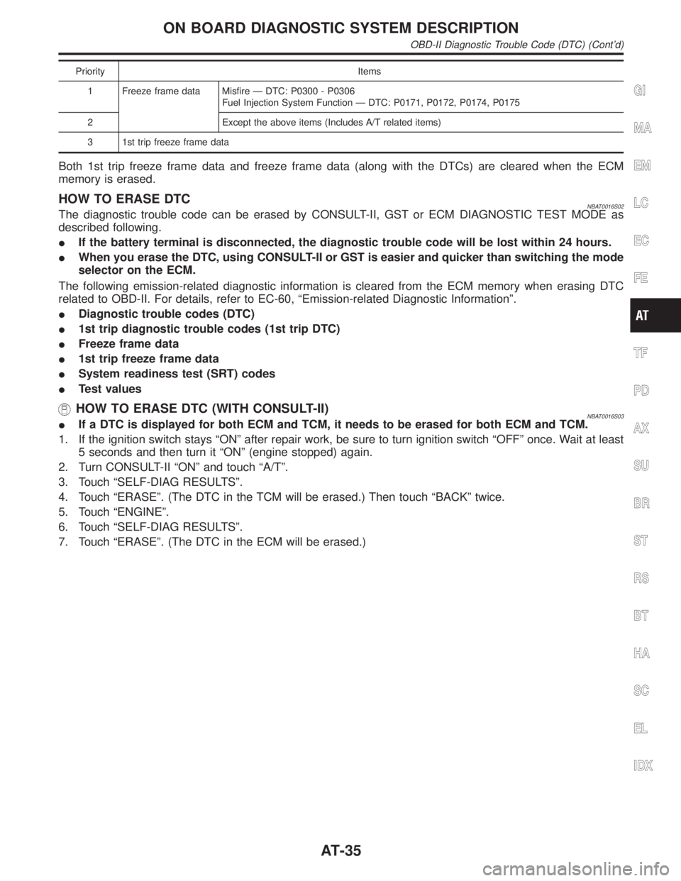
Both 1st trip freeze frame data and freeze frame data (along with the DTCs) are cleared when the ECM
memory is erased.
HOW TO ERASE DTCNBAT0016S02The diagnostic trouble code can be erased by CONSULT-II, GST or ECM DIAGNOSTIC TEST MODE as
described following.
IIf the battery terminal is disconnected, the diagnostic trouble code will be lost within 24 hours.
IWhen you erase the DTC, using CONSULT-II or GST is easier and quicker than switching the mode
selector on the ECM.
The following emission-related diagnostic information is cleared from the ECM memory when erasing DTC
related to OBD-II. For details, refer to EC-60, ªEmission-related Diagnostic Informationº.
IDiagnostic trouble codes (DTC)
I1st trip diagnostic trouble codes (1st trip DTC)
IFreeze frame data
I1st trip freeze frame data
ISystem readiness test (SRT) codes
ITest values
HOW TO ERASE DTC (WITH CONSULT-II)NBAT0016S03IIf a DTC is displayed for both ECM and TCM, it needs to be erased for both ECM and TCM.
1. If the ignition switch stays ªONº after repair work, be sure to turn ignition switch ªOFFº once. Wait at least
5 seconds and then turn it ªONº (engine stopped) again.
2. Turn CONSULT-II ªONº and touch ªA/Tº.
3. Touch ªSELF-DIAG RESULTSº.
4. Touch ªERASEº. (The DTC in the TCM will be erased.) Then touch ªBACKº twice.
5. Touch ªENGINEº.
6. Touch ªSELF-DIAG RESULTSº.
7. Touch ªERASEº. (The DTC in the ECM will be erased.)
GI
MA
EM
LC
EC
FE
TF
PD
AX
SU
BR
ST
RS
BT
HA
SC
EL
IDX
ON BOARD DIAGNOSTIC SYSTEM DESCRIPTION
OBD-II Diagnostic Trouble Code (DTC) (Cont'd)
AT-35
Page 42 of 2395
SAT964I
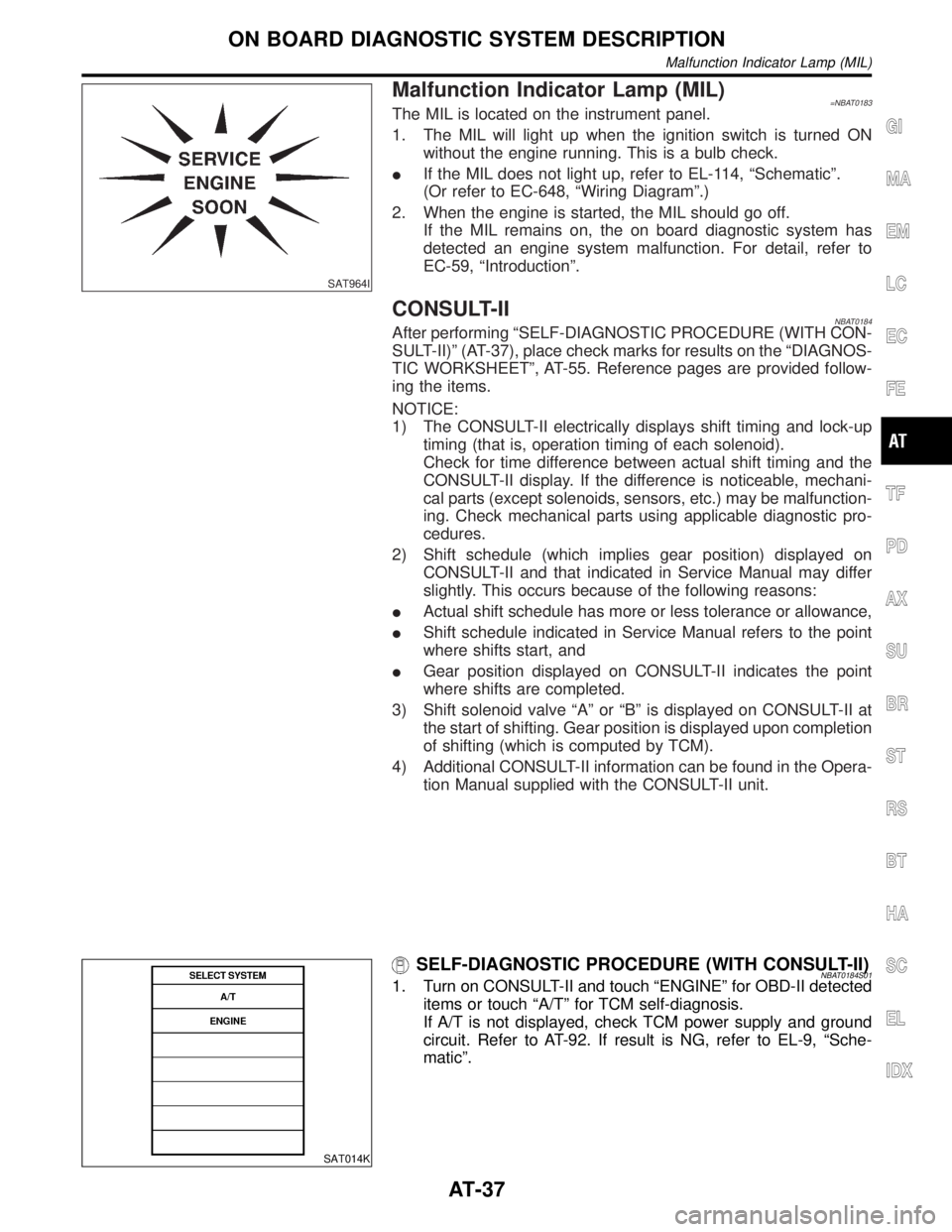
Malfunction Indicator Lamp (MIL)=NBAT0183The MIL is located on the instrument panel.
1. The MIL will light up when the ignition switch is turned ON
without the engine running. This is a bulb check.
IIf the MIL does not light up, refer to EL-114, ªSchematicº.
(Or refer to EC-648, ªWiring Diagramº.)
2. When the engine is started, the MIL should go off.
If the MIL remains on, the on board diagnostic system has
detected an engine system malfunction. For detail, refer to
EC-59, ªIntroductionº.
CONSULT-IINBAT0184After performing ªSELF-DIAGNOSTIC PROCEDURE (WITH CON-
SULT-II)º (AT-37), place check marks for results on the ªDIAGNOS-
TIC WORKSHEETº, AT-55. Reference pages are provided follow-
ing the items.
NOTICE:
1) The CONSULT-II electrically displays shift timing and lock-up
timing (that is, operation timing of each solenoid).
Check for time difference between actual shift timing and the
CONSULT-II display. If the difference is noticeable, mechani-
cal parts (except solenoids, sensors, etc.) may be malfunction-
ing. Check mechanical parts using applicable diagnostic pro-
cedures.
2) Shift schedule (which implies gear position) displayed on
CONSULT-II and that indicated in Service Manual may differ
slightly. This occurs because of the following reasons:
IActual shift schedule has more or less tolerance or allowance,
IShift schedule indicated in Service Manual refers to the point
where shifts start, and
IGear position displayed on CONSULT-II indicates the point
where shifts are completed.
3) Shift solenoid valve ªAº or ªBº is displayed on CONSULT-II at
the start of shifting. Gear position is displayed upon completion
of shifting (which is computed by TCM).
4) Additional CONSULT-II information can be found in the Opera-
tion Manual supplied with the CONSULT-II unit.
SAT014K
SELF-DIAGNOSTIC PROCEDURE (WITH CONSULT-II)NBAT0184S011. Turn on CONSULT-II and touch ªENGINEº for OBD-II detected
items or touch ªA/Tº for TCM self-diagnosis.
If A/T is not displayed, check TCM power supply and ground
circuit. Refer to AT-92. If result is NG, refer to EL-9, ªSche-
maticº.
GI
MA
EM
LC
EC
FE
TF
PD
AX
SU
BR
ST
RS
BT
HA
SC
EL
IDX
ON BOARD DIAGNOSTIC SYSTEM DESCRIPTION
Malfunction Indicator Lamp (MIL)
AT-37
Page 43 of 2395

SAT987J
2. Touch ªSELF-DIAG RESULTSº.
Display shows malfunction experienced since the last erasing
operation.
CONSULT-II performs REAL-TIME SELF-DIAGNOSIS.
Also, any malfunction detected while in this mode will be dis-
played at real time.
SELF-DIAGNOSTIC RESULT TEST MODENBAT0184S02
Detected items
(Screen terms for CONSULT-II, ªSELF-DIAG
RESULTSº test mode)
Malfunction is detected when ...TCM self-diagnosis OBD-II (DTC)
Available by
O/D OFF
indicator lamp or
ªA/Tº on CONSULT-IIAvailable by
malfunction
indicator lamp*2,
ªENGINEº on CON-
SULT-II or GST ªA/Tº ªENGINEº
PNP switch circuitITCM does not receive the cor-
rect voltage signal (based on
the gear position) from the
switch.Ð P0705
ÐPNP SW/CIRC
Revolution sensorITCM does not receive the
proper voltage signal from the
sensor.X P0720
VHCL SPEED
SEN´A/TVEH SPD SEN/CIR
AT
Vehicle speed sensor (Meter)ITCM does not receive the
proper voltage signal from the
sensor.XÐ
VHCL SPEED
SEN´MTRÐ
A/T 1st gear functionIA/T cannot be shifted to the 1st
gear position even if electrical
circuit is good.Ð P0731*1
ÐA/T 1ST GR FNCTN
A/T 2nd gear functionIA/T cannot be shifted to the 2nd
gear position even if electrical
circuit is good.Ð P0732*1
ÐA/T 2ND GR FNCTN
A/T 3rd gear functionIA/T cannot be shifted to the 3rd
gear position even if electrical
circuit is good.Ð P0733*1
ÐA/T 3RD GR FNCTN
A/T 4th gear functionIA/T cannot be shifted to the 4th
gear position even if electrical
circuit is good.Ð P0734*1
ÐA/T 4TH GR FNCTN
A/T TCC S/V function (lock-up)IA/T cannot perform lock-up
even if electrical circuit is good.Ð P0744*1
Ð A/T TCC S/V FNCTN
Shift solenoid valve AITCM detects an improper volt-
age drop when it tries to operate
the solenoid valve.X P0750
SHIFT SOLENOID/V
ASFT SOL A/CIRC
Shift solenoid valve BITCM detects an improper volt-
age drop when it tries to operate
the solenoid valve.X P0755
SHIFT SOLENOID/V
BSFT SOL B/CIRC
ON BOARD DIAGNOSTIC SYSTEM DESCRIPTION
CONSULT-II (Cont'd)
AT-38
Page 45 of 2395

X: Applicable
Ð: Not applicable
*1: These malfunctions cannot be displayed by MIL
if another malfunction is assigned to MIL.
*2: Refer to EC-74, ªDESCRIPTIONº.
DATA MONITOR MODE (A/T)NBAT0184S03
Item DisplayMonitor item
Description Remarks
TCM input
signalsMain sig-
nals
Vehicle speed sensor 1
(A/T)
(Revolution sensor)VHCL/S SE´A/T
[km/h] or [mph]
XÐIVehicle speed computed
from signal of revolution
sensor is displayed.When racing engine in ªNº
or ªPº position with vehicle
stationary, CONSULT-II
data may not indicate 0
km/h (0 mph).
Vehicle speed sensor 2
(Meter)VHCL/S SE´MTR
[km/h] or [mph]
XÐIVehicle speed computed
from signal of vehicle
speed sensor is dis-
played.Vehicle speed display may
not be accurate under
approx. 10 km/h (6 mph). It
may not indicate 0 km/h (0
mph) when vehicle is sta-
tionary.
Throttle position sensor THRTL POS
SEN
[V]XÐIThrottle position sensor
signal voltage is dis-
played.
A/T fluid temperature sen-
sorFLUID TEMP SE
[V]
XÐIA/T fluid temperature
sensor signal voltage is
displayed.
ISignal voltage lowers as
fluid temperature rises.
Battery voltage BATTERY VOLT
[V]XÐISource voltage of TCM
is displayed.
Engine speed ENGINE SPEED
[rpm]
XXIEngine speed, computed
from engine speed
signal, is displayed.Engine speed display may
not be accurate under
approx. 800 rpm. It may
not indicate 0 rpm even
when engine is not run-
ning.
Turbine revolution sensor TURBINE REV
[rpm]
XÐITurbine revolution com-
puted from signal of tur-
bine revolution sensor is
displayed.Error may occur under
approx. 800 rpm and will
not indicate 0 rpm even if
engine is not running.
Overdrive control switch OVERDRIVE SW
[ON/OFF] X ÐION/OFF state computed
from signal of overdrive
control SW is displayed.
PN position switch PN POSI SW
[ON/OFF] X ÐION/OFF state computed
from signal of PN posi-
tion SW is displayed.
R position switch R POSITION SW
[ON/OFF] X ÐION/OFF state computed
from signal of R position
SW is displayed.
D position switch D POSITION SW
[ON/OFF] X ÐION/OFF state computed
from signal of D position
SW is displayed.
2 position switch 2 POSITION SW
[ON/OFF]
XÐION/OFF status, com-
puted from signal of 2
position SW, is dis-
played.
ON BOARD DIAGNOSTIC SYSTEM DESCRIPTION
CONSULT-II (Cont'd)
AT-40
Page 46 of 2395
![INFINITI QX4 2001 Factory Service Manual Item DisplayMonitor item
Description Remarks
TCM input
signalsMain sig-
nals
1 position switch 1 POSITION SW
[ON/OFF]
XÐION/OFF status, com-
puted from signal of 1
position SW, is dis-
played.
ASCD c INFINITI QX4 2001 Factory Service Manual Item DisplayMonitor item
Description Remarks
TCM input
signalsMain sig-
nals
1 position switch 1 POSITION SW
[ON/OFF]
XÐION/OFF status, com-
puted from signal of 1
position SW, is dis-
played.
ASCD c](/img/42/57027/w960_57027-45.png)
Item DisplayMonitor item
Description Remarks
TCM input
signalsMain sig-
nals
1 position switch 1 POSITION SW
[ON/OFF]
XÐION/OFF status, com-
puted from signal of 1
position SW, is dis-
played.
ASCD cruise signal ASCD-CRUISE
[ON/OFF]
XÐIStatus of ASCD cruise
signal is displayed.
ON ... Cruising state
OFF ... Normal running
stateIThis is displayed even
when no ASCD is
mounted.
ASCD OD cut signal ASCD-OD CUT
[ON/OFF]
XÐIStatus of ASCD OD
release signal is dis-
played.
ON ... OD released
OFF ... OD not releasedIThis is displayed even
when no ASCD is
mounted.
Kickdown switch KICKDOWN SW
[ON/OFF]
XÐION/OFF status, com-
puted from signal of
kickdown SW, is dis-
played.IThis is displayed even
when no kickdown
switch is equipped.
Closed throttle position
switchCLOSED
THL/SW
[ON/OFF]XÐION/OFF status, com-
puted from signal of
closed throttle position
SW, is displayed.
Wide open throttle position
switchW/O THRL/P-SW
[ON/OFF]
XÐION/OFF status, com-
puted from signal of
wide open throttle posi-
tion SW, is displayed.
Stop lamp switch BRAKE SW
[ON/OFF]
XÐION/OFF status is dis-
played.
ON ... Brake pedal is
depressed.
OFF ... Brake pedal is
released.
Gear position GEAR
ÐXIGear position data used
for computation by TCM,
is displayed.
Selector lever position SLCT LVR POSI
ÐXISelector lever position
data, used for computa-
tion by TCM, is dis-
played.IA specific value used for
control is displayed if
fail-safe is activated due
to error.
Vehicle speed VEHICLE
SPEED
[km/h] or [mph]ÐXIVehicle speed data,
used for computation by
TCM, is displayed.
Throttle position THROTTLE
POSI
[/8]ÐXIThrottle position data,
used for computation by
TCM, is displayed.IA specific value used for
control is displayed if
fail-safe is activated due
to error.
Line pressure duty LINE PRES DTY
[%]
ÐXIControl value of line
pressure solenoid valve,
computed by TCM from
each input signal, is dis-
played.GI
MA
EM
LC
EC
FE
TF
PD
AX
SU
BR
ST
RS
BT
HA
SC
EL
IDX
ON BOARD DIAGNOSTIC SYSTEM DESCRIPTION
CONSULT-II (Cont'd)
AT-41