air filter INFINITI QX4 2001 Factory User Guide
[x] Cancel search | Manufacturer: INFINITI, Model Year: 2001, Model line: QX4, Model: INFINITI QX4 2001Pages: 2395, PDF Size: 43.2 MB
Page 249 of 2395

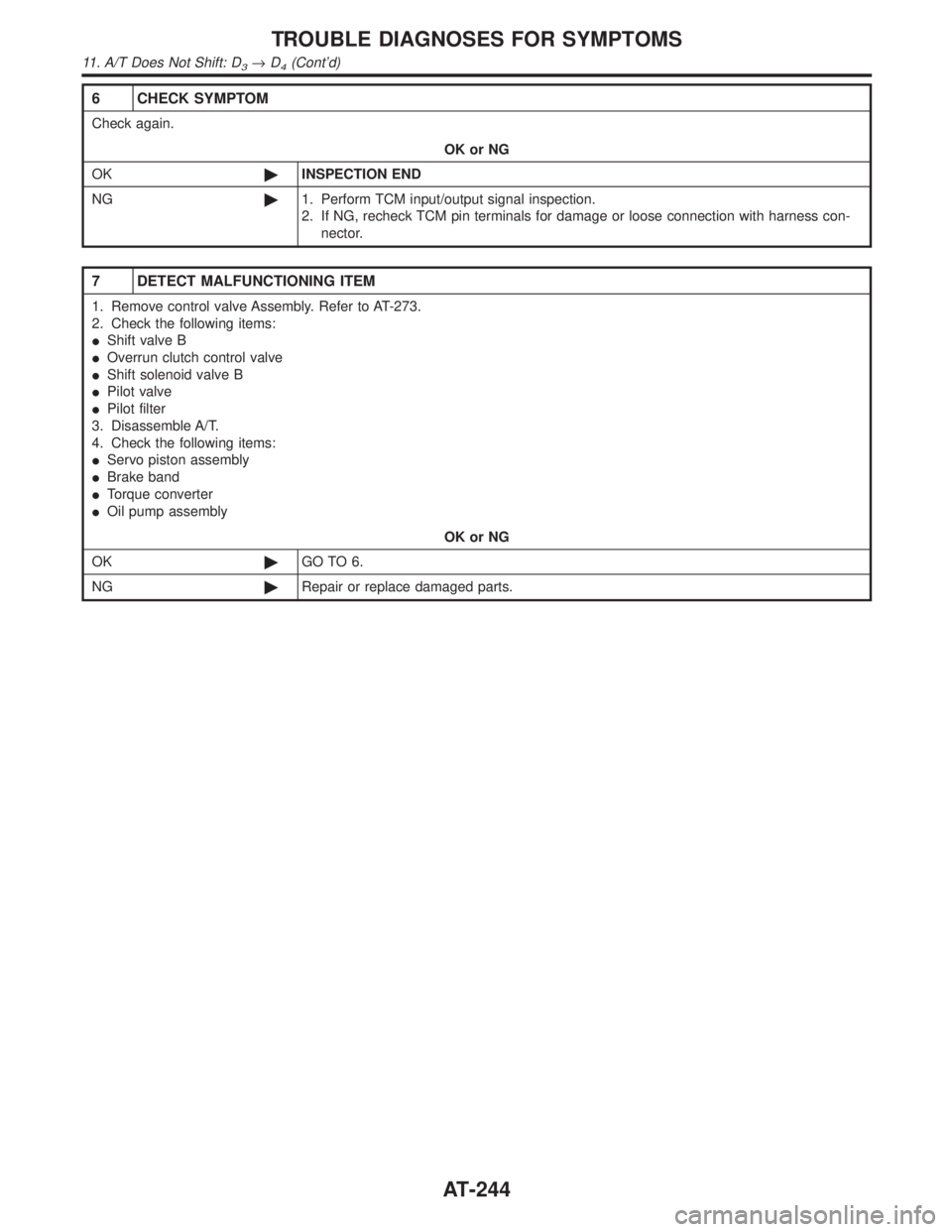
6 CHECK SYMPTOM
Check again.
OK or NG
OK©INSPECTION END
NG©1. Perform TCM input/output signal inspection.
2. If NG, recheck TCM pin terminals for damage or loose connection with harness con-
nector.
7 DETECT MALFUNCTIONING ITEM
1. Remove control valve Assembly. Refer to AT-273.
2. Check the following items:
IShift valve B
IOverrun clutch control valve
IShift solenoid valve B
IPilot valve
IPilot filter
3. Disassemble A/T.
4. Check the following items:
IServo piston assembly
IBrake band
ITorque converter
IOil pump assembly
OK or NG
OK©GO TO 6.
NG©Repair or replace damaged parts.
TROUBLE DIAGNOSES FOR SYMPTOMS
11. A/T Does Not Shift: D3®D4(Cont'd)
AT-244
Page 250 of 2395

12. A/T Does Not Perform Lock-up=NBAT0084SYMPTOM:
A/T does not perform lock-up at the specified speed.
1 CHECK SELF-DIAGNOSTIC RESULTS
Does self-diagnosis show damage to torque converter clutch solenoid valve circuit after cruise test?
SAT581I
YesorNo
Ye s©Check torque converter clutch solenoid valve circuit. Refer to ªDTC P0740º, AT-148.
No©GO TO 2.
2 CHECK THROTTLE POSITION SENSOR
Check throttle position sensor. Refer to EC-174, ªDescriptionº.
SAT142K
OK or NG
OK©GO TO 3.
NG©Repair or replace throttle position sensor.
3 DETECT MALFUNCTIONING ITEM
1. Remove control valve. Refer to AT-273.
2. Check following items:
ITorque converter clutch control valve
ITorque converter relief valve
ITorque converter clutch solenoid valve
IPilot valve
IPilot filter
OK or NG
OK©GO TO 4.
NG©Repair or replace damaged parts.
GI
MA
EM
LC
EC
FE
TF
PD
AX
SU
BR
ST
RS
BT
HA
SC
EL
IDX
TROUBLE DIAGNOSES FOR SYMPTOMS
12. A/T Does Not Perform Lock-up
AT-245
Page 252 of 2395

13. A/T Does Not Hold Lock-up Condition=NBAT0085SYMPTOM:
A/T does not hold lock-up condition for more than 30 seconds.
1 CHECK DIAGNOSTIC RESULTS
Does self-diagnosis show damage to engine speed signal circuit after cruise test?
SAT582I
YesorNo
Ye s©Check engine speed signal circuit. Refer to ªDTC P0725º, AT-116.
No©GO TO 2.
2 CHECK A/T FLUID CONDITION
1. Remove oil pan.
2. Check A/T fluid condition.
SAT171B
OK or NG
OK©GO TO 3.
NG©GO TO 5.
3 DETECT MALFUNCTIONING ITEM
1. Remove control valve assembly. Refer to AT-273.
2. Check the following items:
ITorque converter clutch control valve
IPilot valve
IPilot filter
OK or NG
OK©GO TO 4.
NG©Repair or replace damaged parts.
GI
MA
EM
LC
EC
FE
TF
PD
AX
SU
BR
ST
RS
BT
HA
SC
EL
IDX
TROUBLE DIAGNOSES FOR SYMPTOMS
13. A/T Does Not Hold Lock-up Condition
AT-247
Page 253 of 2395

4 CHECK SYMPTOM
Check again.
OK or NG
OK©INSPECTION END
NG©1. Perform TCM input/output signal inspection.
2. If NG, recheck TCM pin terminals for damage or loose connection with harness con-
nector.
5 DETECT MALFUNCTIONING ITEM
1. Remove control valve assembly. Refer to AT-273.
2. Check the following items:
ITorque converter clutch control valve
IPilot valve
IPilot filter
3. Disassemble A/T.
4. Check torque converter and oil pump assembly.
OK or NG
OK©GO TO 4.
NG©Repair or replace damaged parts.
TROUBLE DIAGNOSES FOR SYMPTOMS
13. A/T Does Not Hold Lock-up Condition (Cont'd)
AT-248
Page 307 of 2395

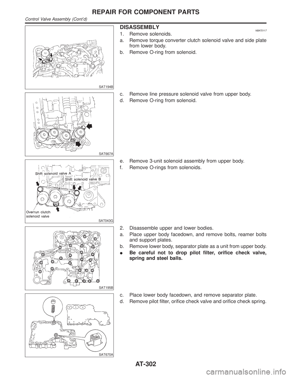
SAT194B
DISASSEMBLYNBAT01171. Remove solenoids.
a. Remove torque converter clutch solenoid valve and side plate
from lower body.
b. Remove O-ring from solenoid.
SAT667A
c. Remove line pressure solenoid valve from upper body.
d. Remove O-ring from solenoid.
SAT043G
e. Remove 3-unit solenoid assembly from upper body.
f. Remove O-rings from solenoids.
SAT195B
2. Disassemble upper and lower bodies.
a. Place upper body facedown, and remove bolts, reamer bolts
and support plates.
b. Remove lower body, separator plate as a unit from upper body.
IBe careful not to drop pilot filter, orifice check valve,
spring and steel balls.
SAT670A
c. Place lower body facedown, and remove separator plate.
d. Remove pilot filter, orifice check valve and orifice check spring.
REPAIR FOR COMPONENT PARTS
Control Valve Assembly (Cont'd)
AT-302
Page 309 of 2395

SAT676A
Pilot FilterNBAT0118S03ICheck to make sure that filter is not clogged or damaged.
SAT149G
Torque Converter Clutch Solenoid ValveNBAT0118S04ICheck that filter is not clogged or damaged.
IMeasure resistance. Refer to ªComponent Inspectionº, AT-152.
Line Pressure Solenoid ValveNBAT0118S05ICheck that filter is not clogged or damaged.
IMeasure resistance. Refer to ªComponent Inspectionº, AT-167.
SAT095B
3-Unit Solenoid Assembly (Overrun Clutch Solenoid
Valve and Shift Solenoid Valves A and B)
NBAT0118S06IMeasure resistance of each solenoid. Refer to ªComponent
Inspectionº, AT-171, AT-175 and AT-189.
SAT096BA
A/T Fluid Temperature Sensor and SwitchNBAT0118S07IMeasure resistance. Refer to ªComponent Inspectionº, AT-110
and AT-264.
SAT671A
ASSEMBLYNBAT01191. Install upper and lower bodies.
a. Place oil circuit of upper body face up. Install steel balls in their
proper positions.
REPAIR FOR COMPONENT PARTS
Control Valve Assembly (Cont'd)
AT-304
Page 310 of 2395

SAT681A
b. Install reamer bolts from bottom of upper body.
SAT682A
c. Place oil circuit of lower body face up. Install orifice check
spring, orifice check valve and pilot filter.
SAT197B
d. Install lower separator plate on lower body.
e. Install and temporarily tighten support plates, A/T fluid tem-
perature sensor and tube brackets.
SAT198B
f. Temporarily assemble lower and upper bodies, using reamer
bolt as a guide.
IBe careful not to dislocate or drop steel balls, orifice
check spring, orifice check valve and pilot filter.
GI
MA
EM
LC
EC
FE
TF
PD
AX
SU
BR
ST
RS
BT
HA
SC
EL
IDX
REPAIR FOR COMPONENT PARTS
Control Valve Assembly (Cont'd)
AT-305
Page 834 of 2395

4 CHECK FUEL PRESSURE
1. Release fuel pressure to zero. Refer to EC-39.
2. Install fuel pressure gauge and check fuel pressure. Refer to EC-39.
At idling:
When fuel pressure regulator valve vacuum hose is connected.
235 kPa (2.4 kg/cm
2, 34 psi)
When fuel pressure regulator valve vacuum hose is disconnected.
294 kPa (3.0 kg/cm
2, 43 psi)
OK or NG
OK©GO TO 6.
NG©GO TO 5.
5 DETECT MALFUNCTIONING PART
Check the following.
IFuel pump and circuit (Refer to EC-625.)
IFuel pressure regulator (Refer to EC-40.)
IFuel lines (Refer to MA-16, ªChecking Fuel Linesº.)
IFuel filter for clogging
©Repair or replace.
6 CHECK MASS AIR FLOW SENSOR
With CONSULT-II
1. Install all removed parts.
2. Check ªMASS AIR FLOWº in ªDATA MONITORº mode with CONSULT-II.
2.0 - 6.0 g´m/sec: at idling
7.0 - 20.0 g´m/sec: at 2,500 rpm
With GST
1. Install all removed parts.
2. Check mass air flow sensor signal in MODE 1 with GST.
2.0 - 6.0 g´m/sec: at idling
7.0 - 20.0 g´m/sec: at 2,500 rpm
OK or NG
OK©GO TO 7.
NG©Check connectors for rusted terminals or loose connections in the mass air flow sensor
circuit or engine grounds. Refer to EC-150.
GI
MA
EM
LC
FE
AT
TF
PD
AX
SU
BR
ST
RS
BT
HA
SC
EL
IDX
DTC P0171 (RIGHT, -B1), P0174 (LEFT, -B2) FUEL INJECTION SYSTEM
FUNCTION (LEAN)
Diagnostic Procedure (Cont'd)
EC-299
Page 859 of 2395

8 CHECK FUEL PRESSURE
1. Install all removed parts.
2. Release fuel pressure to zero. Refer to EC-39.
3. Install fuel pressure gauge and check fuel pressure. Refer to EC-39.
At idle:
Approx. 235 kPa (2.4 kg/cm
2, 34 psi)
OK or NG
OK©GO TO 10.
NG©GO TO 9.
9 DETECT MALFUNCTIONING PART
Check the following.
IFuel pump and circuit (Refer to EC-625.)
IFuel pressure regulator (Refer to EC-40.)
IFuel lines (Refer to MA-16, ªChecking Fuel Linesº.)
IFuel filter for clogging
©Repair or replace.
10 CHECK IGNITION TIMING
Check the following items. Refer to ªBasic Inspectionº, EC-101.
MTBL0655
OK or NG
OK (With CONSULT-II)©GO TO 11.
OK (Without CONSULT-
II)©GO TO 12.
NG©Follow the ªBasic Inspectionº.
DTC P0300 - P0306 NO.6-1CYLINDER MISFIRE, MULTIPLE CYLINDER
MISFIRE
Diagnostic Procedure (Cont'd)
EC-324
Page 1745 of 2395

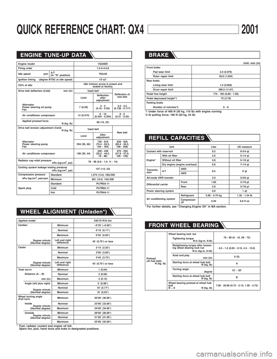
QUICK REFERENCE CHART: QX42001
Engine model VQ35DE
Firing order 1-2-3-4-5-6
Idle speed rpmA/T
(in ªNº position)750 50
Ignition timing (degree BTDC at idle speed) 15É 2É
CO% at idleIdle mixture screw is preset and
sealed at factory.
Drive belt deflection (Cold) mm (in) Used belt
Deflection of
new belt
LimitDeflection
after
adjustment
Alternator
Power steering oil pump
Fan7 (0.28)4-5
(0.16 - 0.20)3.5 - 4.5
(0.138 - 0.177)
Air conditioner compressor 12 (0.472)9-10
(0.354 - 0.394)8-9
(0.31 - 0.35)
Applied pressed force
N (kg, lb)98 (10, 22)
Drive belt tension adjustment (Cold)
N (kg, lb)Used belt
New belt
LimitAfter
adjustment
Alternator
Power steering pump
Fan294 (30, 66)730 - 818
(74.4 - 83.5,
164 - 184)838 - 926
(85.4 - 94.5,
188 - 208)
Air conditioner compressor 196 (20, 44)348 - 436
(35.5 - 44.5,
78 - 98)470 - 559
(47.9 - 57.0,
106 - 126)
Radiator cap relief pressure
kPa (kg/cm
2, psi)78 - 98 (0.8 - 1.0, 11 - 14)
Cooling system leakage testing pressure
kPa (kg/cm
2, psi)157 (1.6, 23)
Compression pressure
kPa (kg/cm
2, psi)/rpmStandard 1,275 (13.0, 185)/300
Minimum 981 (10.0, 142)/300
Spark plugStandard PLFR5A-11
Cold PLFR6A-11
Hot PLFR4A-11
Applied model 245/70 R16 tire
Camber
Degree minute
(Decimal degree)Minimum þ0É35¢(þ0.58É)
Nominal 0É10¢(0.17É)
Maximum 0É55¢(0.92É)
Left and right
difference45¢(0.75É) or less
Caster
Degree minute
(Decimal degree)Minimum 2É15¢(2.25É)
Nominal 3É00¢(3.00É)
Maximum 3É45¢(3.75É)
Left and right
difference45¢(0.75É) or less
Total toe-in Minimum 1 (0.04)
Distance (A þ B)
mm (in)Nominal 2 (0.08)
Maximum 3 (0.12)
Angle (left plus right)
Degree minute
(Decimal degree)Minimum 5¢(0.08É)
Nominal 10¢(0.17É)
Maximum 15¢(0.25É)
Wheel turning angle
(Full turn)Minimum 30É00¢(30.00É)
Inside
Degree minute
(Decimal degree)Nominal 33É00¢(33.00É)
Maximum 34É00¢(34.00É)
Outside
Degree minute
(Decimal degree)Minimum 28É00¢(28.00É)
Nominal 31É00¢(31.00É)
Maximum 32É00¢(32.00É)
* Fuel, radiator coolant and engine oil full.
Spare tire, jack, hand tools and mats in designated positions.
Unit: mm (in)Front brake
Pad wear limit 2.0 (0.079)
Rotor repair limit 26.0 (1.024)
Rear brake
Lining wear limit 1.5 (0.059)
Drum repair limit 296.5 (11.67)
Pedal free height 175 - 185 (6.89 - 7.28)
Pedal depressed height*1 70 (2.76)
Parking brake
Number of notches*2 6 - 8
*1 Under force of 490 N (50 kg, 110 lb) with engine running
*2 At pulling force: 196 N (20 kg, 44 lb)
Unit Liter US measure
Coolant with reservoir 9.2 9-3/4 qt
Engine*With oil filter 5.0 5-1/4 qt
Without oil filter 4.8 5-1/8 qt
Dry engine (engine overhaul) 6.8 7-1/4 qt
Transmis-
sionA/T2WD
8.5 9 qt
4WD
All-mode 4WD transfer 3.0 2-5/8 qt
Differential carrierFront 1.85 3-7/8 pt
Rear 2.8 5-7/8 pt
Power steering system 0.9 1 qt
Air conditioning systemRefrigerant 0.60 - 0.70 kg 1.32 - 1.54 lb
Compressor
oil0.20 6.8 fl oz
* For further details, see ªChanging Engine Oilº in MA section.
Preload
(At hub bolt)
N (kg, lb)Wheel bearing lock nut
78-98(8-10,58-72)
Tightening torque
N×m (kg-m, ft-lb)
Retightening torque after loosen-
ing wheel bearing lock nut
N×m (kg-m, in-lb)0.5 - 1.5 (0.05 - 0.15, 4.3 - 13.0)
Axial end play
mm (in)0 (0)
Starting force at wheel hub bolt
N (kg, lb)A
Turning angle
degree15É - 30É
Starting force at wheel hub bolt
N (kg, lb)B
Wheel bearing preload at wheel hub
bolt
B þ A N (kg, lb)7.06 - 20.99 (0.72 - 2.14, 1.59 - 4.72)