light INFINITI QX4 2001 Factory User Guide
[x] Cancel search | Manufacturer: INFINITI, Model Year: 2001, Model line: QX4, Model: INFINITI QX4 2001Pages: 2395, PDF Size: 43.2 MB
Page 256 of 2395
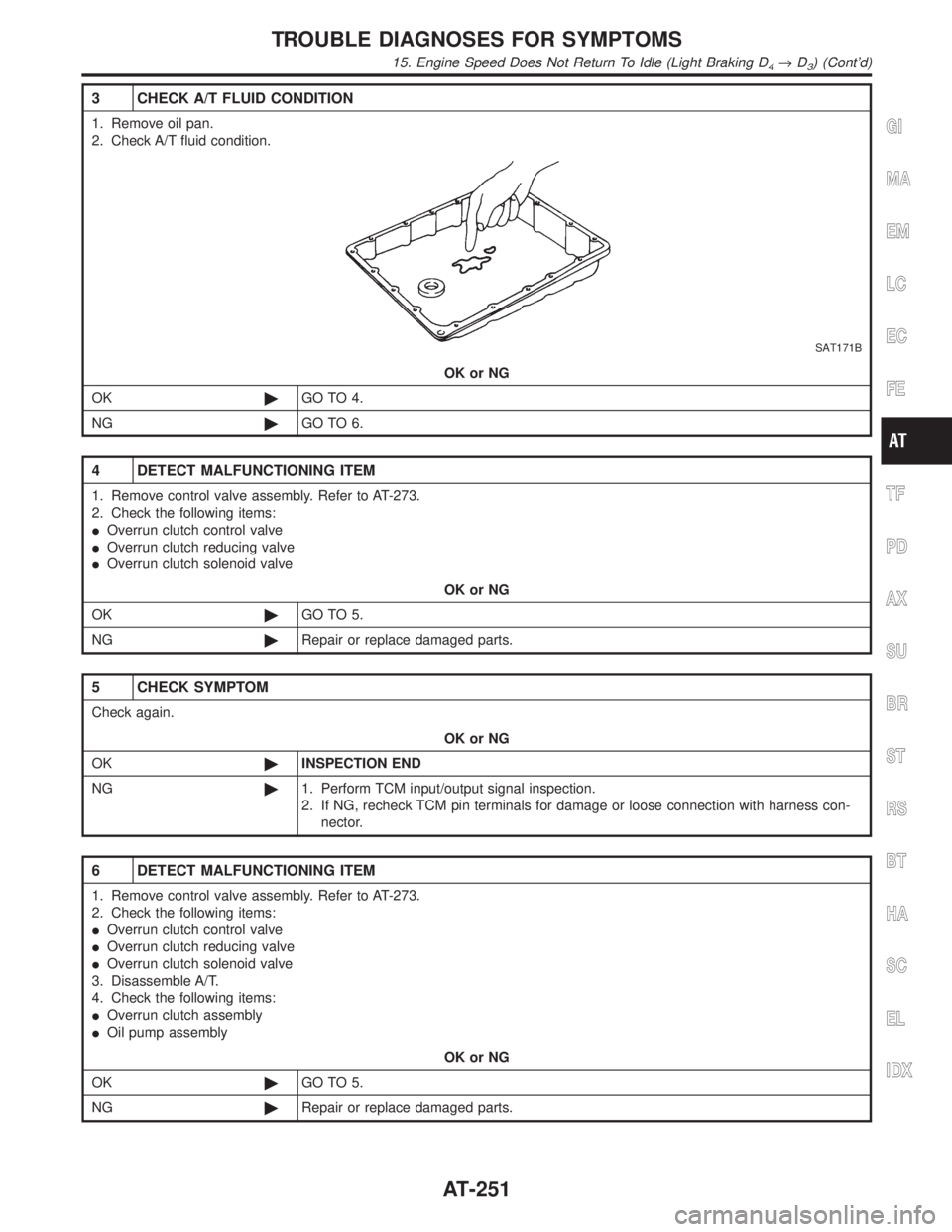
3 CHECK A/T FLUID CONDITION
1. Remove oil pan.
2. Check A/T fluid condition.
SAT171B
OK or NG
OK©GO TO 4.
NG©GO TO 6.
4 DETECT MALFUNCTIONING ITEM
1. Remove control valve assembly. Refer to AT-273.
2. Check the following items:
IOverrun clutch control valve
IOverrun clutch reducing valve
IOverrun clutch solenoid valve
OK or NG
OK©GO TO 5.
NG©Repair or replace damaged parts.
5 CHECK SYMPTOM
Check again.
OK or NG
OK©INSPECTION END
NG©1. Perform TCM input/output signal inspection.
2. If NG, recheck TCM pin terminals for damage or loose connection with harness con-
nector.
6 DETECT MALFUNCTIONING ITEM
1. Remove control valve assembly. Refer to AT-273.
2. Check the following items:
IOverrun clutch control valve
IOverrun clutch reducing valve
IOverrun clutch solenoid valve
3. Disassemble A/T.
4. Check the following items:
IOverrun clutch assembly
IOil pump assembly
OK or NG
OK©GO TO 5.
NG©Repair or replace damaged parts.
GI
MA
EM
LC
EC
FE
TF
PD
AX
SU
BR
ST
RS
BT
HA
SC
EL
IDX
TROUBLE DIAGNOSES FOR SYMPTOMS
15. Engine Speed Does Not Return To Idle (Light Braking D4®D3) (Cont'd)
AT-251
Page 261 of 2395
20. Vehicle Does Not Decelerate By Engine
Brake
NBAT0092SYMPTOM:
Vehicle does not decelerate by engine brake when shifting
from 2
2(12)to11.
1 CHECK SYMPTOM
Is ª6. Vehicle Does Not Creep Backward In ªRº Positionº OK?
YesorNo
Ye s©Go to ª15. Engine Speed Does Not Return To Idle (Light Braking D
4,D3)º, AT-250.
No©Go to ª6. Vehicle Does Not Creep Backward In ªRº Positionº, AT-227.
TROUBLE DIAGNOSES FOR SYMPTOMS
20. Vehicle Does Not Decelerate By Engine Brake
AT-256
Page 269 of 2395

SAT132K
Throttle Position SwitchNBAT0204S0403Closed Throttle Position Switch (Idle Position)
ICheck continuity between terminals 5 and 6.
[Refer to ªPreparationº, ªTCM SELF-DIAGNOSTIC PROCE-
DURE (No Tools)º, AT-46.]
Accelerator pedal condition Continuity
Released Yes
Depressed No
ITo adjust closed throttle position switch, refer to EC-431, ªSystem
Descriptionº.
SAT137K
Wide Open Throttle Position Switch
ICheck continuity between terminals 4 and 5.
Accelerator pedal condition Continuity
Released No
Depressed Yes
SAT251JA
A/T Fluid Temperature SwitchNBAT0204S04041. Make sure the A/T fluid warning lamp lights when the key is
inserted and turned to ªONº.
2. Make sure the A/T fluid warning lamp goes off when turning the
ignition switch to ªONº.
3. Check resistance between terminal 10 and ground while
changing temperature as shown at left.
Temperature ÉC (ÉF) Resistance
140 (284) or more Yes
140 (284) or less No
TROUBLE DIAGNOSES FOR SYMPTOMS
21. TCM Self-diagnosis Does Not Activate (PNP, Overdrive Control and Throttle Position Switches Circuit Checks) (Cont'd)
AT-264
Page 284 of 2395
SAT017B
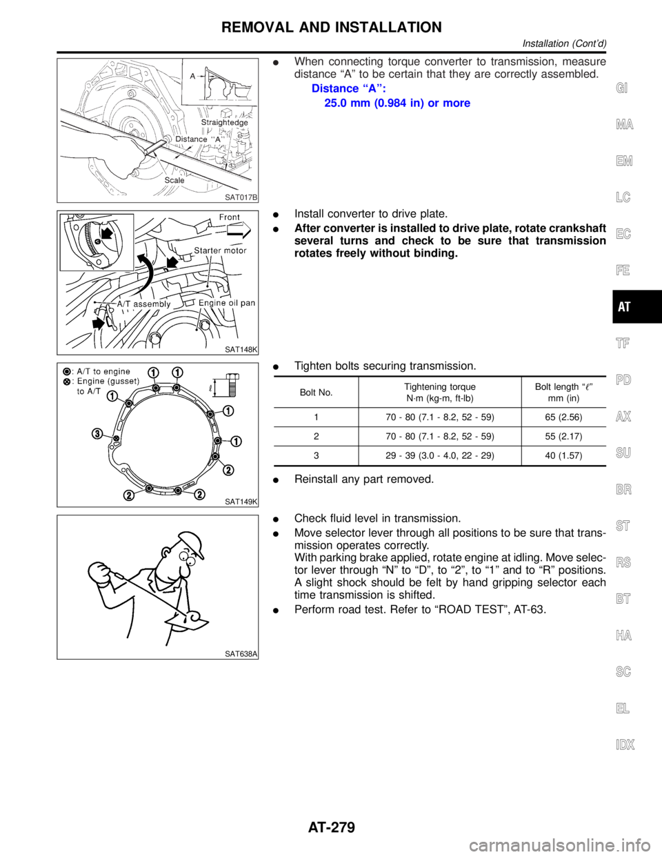
IWhen connecting torque converter to transmission, measure
distance ªAº to be certain that they are correctly assembled.
Distance ªAº:
25.0 mm (0.984 in) or more
SAT148K
IInstall converter to drive plate.
IAfter converter is installed to drive plate, rotate crankshaft
several turns and check to be sure that transmission
rotates freely without binding.
SAT149K
ITighten bolts securing transmission.
Bolt No.Tightening torque
N´m (kg-m, ft-lb)Bolt length ªº
mm (in)
1 70 - 80 (7.1 - 8.2, 52 - 59) 65 (2.56)
2 70 - 80 (7.1 - 8.2, 52 - 59) 55 (2.17)
3 29 - 39 (3.0 - 4.0, 22 - 29) 40 (1.57)
IReinstall any part removed.
SAT638A
ICheck fluid level in transmission.
IMove selector lever through all positions to be sure that trans-
mission operates correctly.
With parking brake applied, rotate engine at idling. Move selec-
tor lever through ªNº to ªDº, to ª2º, to ª1º and to ªRº positions.
A slight shock should be felt by hand gripping selector each
time transmission is shifted.
IPerform road test. Refer to ªROAD TESTº, AT-63.
GI
MA
EM
LC
EC
FE
TF
PD
AX
SU
BR
ST
RS
BT
HA
SC
EL
IDX
REMOVAL AND INSTALLATION
Installation (Cont'd)
AT-279
Page 313 of 2395
SAT834A
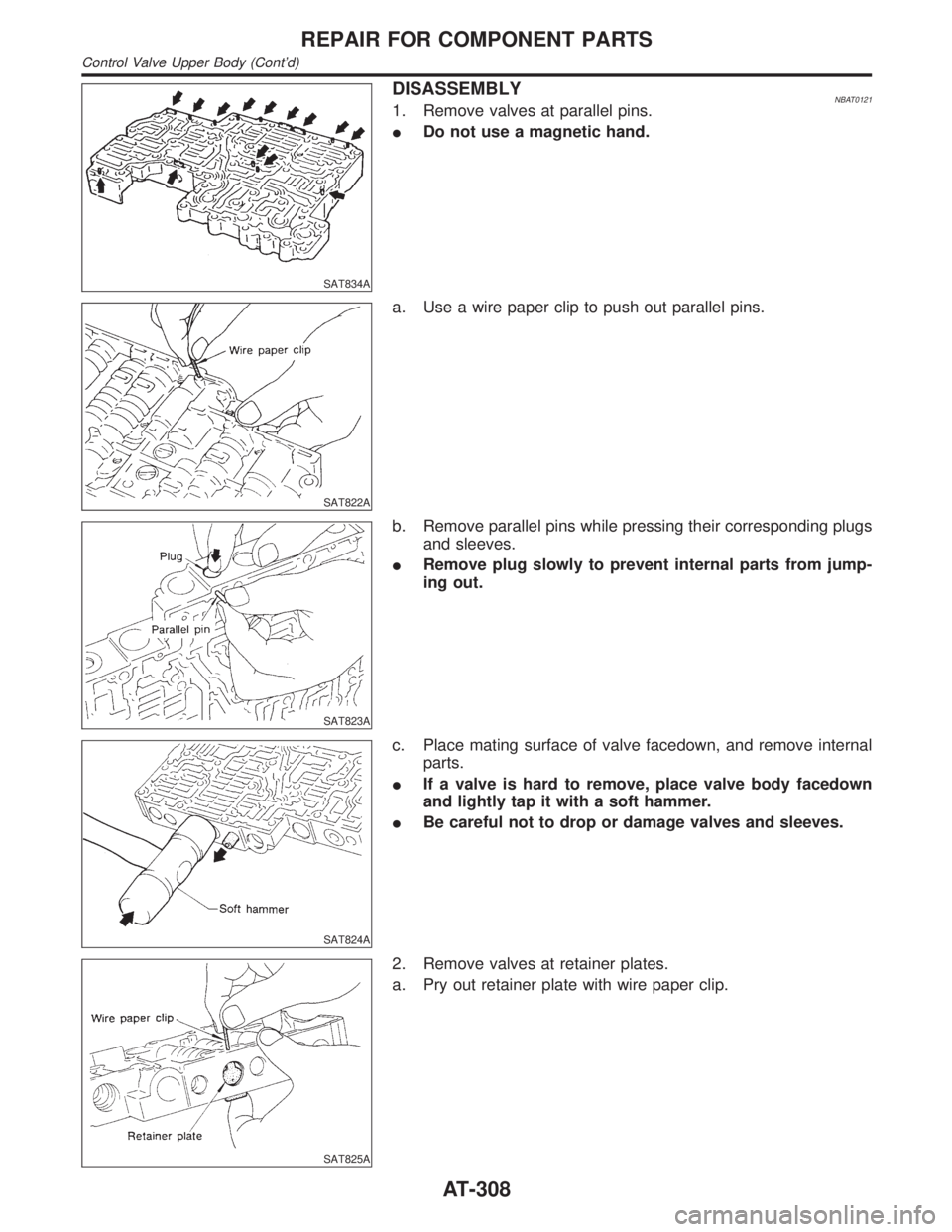
DISASSEMBLYNBAT01211. Remove valves at parallel pins.
IDo not use a magnetic hand.
SAT822A
a. Use a wire paper clip to push out parallel pins.
SAT823A
b. Remove parallel pins while pressing their corresponding plugs
and sleeves.
IRemove plug slowly to prevent internal parts from jump-
ing out.
SAT824A
c. Place mating surface of valve facedown, and remove internal
parts.
IIf a valve is hard to remove, place valve body facedown
and lightly tap it with a soft hammer.
IBe careful not to drop or damage valves and sleeves.
SAT825A
2. Remove valves at retainer plates.
a. Pry out retainer plate with wire paper clip.
REPAIR FOR COMPONENT PARTS
Control Valve Upper Body (Cont'd)
AT-308
Page 314 of 2395
SAT826A
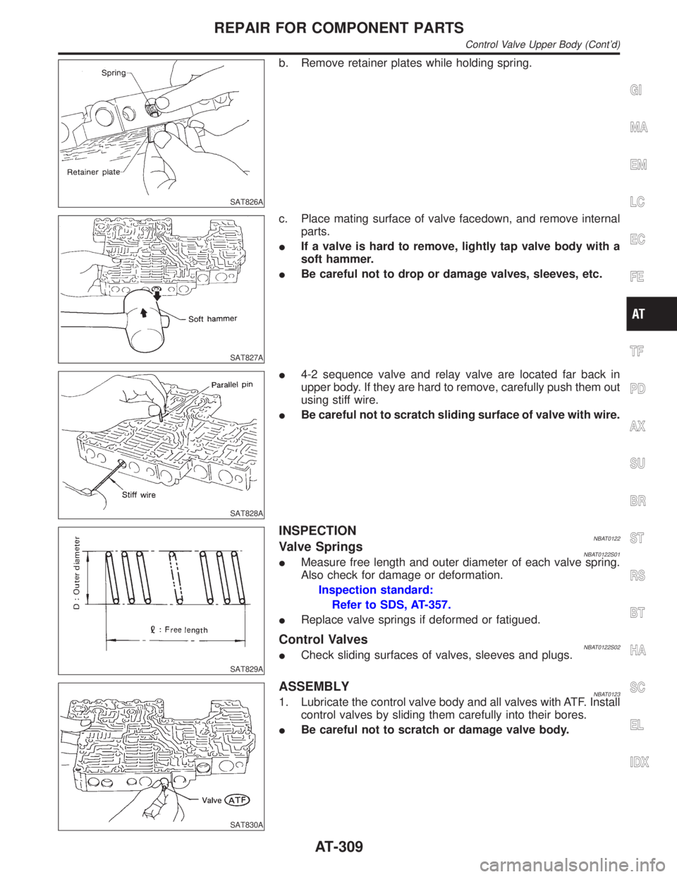
b. Remove retainer plates while holding spring.
SAT827A
c. Place mating surface of valve facedown, and remove internal
parts.
IIf a valve is hard to remove, lightly tap valve body with a
soft hammer.
IBe careful not to drop or damage valves, sleeves, etc.
SAT828A
I4-2 sequence valve and relay valve are located far back in
upper body. If they are hard to remove, carefully push them out
using stiff wire.
IBe careful not to scratch sliding surface of valve with wire.
SAT829A
INSPECTIONNBAT0122Valve SpringsNBAT0122S01IMeasure free length and outer diameter of each valve spring.
Also check for damage or deformation.
Inspection standard:
Refer to SDS, AT-357.
IReplace valve springs if deformed or fatigued.
Control ValvesNBAT0122S02ICheck sliding surfaces of valves, sleeves and plugs.
SAT830A
ASSEMBLYNBAT01231. Lubricate the control valve body and all valves with ATF. Install
control valves by sliding them carefully into their bores.
IBe careful not to scratch or damage valve body.
GI
MA
EM
LC
EC
FE
TF
PD
AX
SU
BR
ST
RS
BT
HA
SC
EL
IDX
REPAIR FOR COMPONENT PARTS
Control Valve Upper Body (Cont'd)
AT-309
Page 315 of 2395
SAT831A
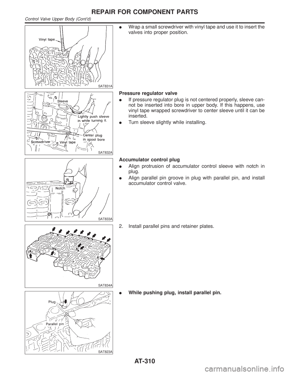
IWrap a small screwdriver with vinyl tape and use it to insert the
valves into proper position.
SAT832A
Pressure regulator valve
IIf pressure regulator plug is not centered properly, sleeve can-
not be inserted into bore in upper body. If this happens, use
vinyl tape wrapped screwdriver to center sleeve until it can be
inserted.
ITurn sleeve slightly while installing.
SAT833A
Accumulator control plug
IAlign protrusion of accumulator control sleeve with notch in
plug.
IAlign parallel pin groove in plug with parallel pin, and install
accumulator control valve.
SAT834A
2. Install parallel pins and retainer plates.
SAT823A
IWhile pushing plug, install parallel pin.
REPAIR FOR COMPONENT PARTS
Control Valve Upper Body (Cont'd)
AT-310
Page 346 of 2395
SAT940A
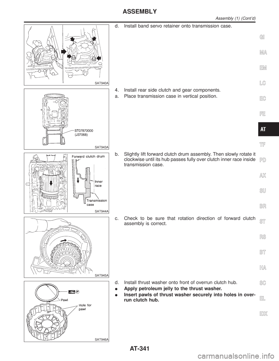
d. Install band servo retainer onto transmission case.
SAT943A
4. Install rear side clutch and gear components.
a. Place transmission case in vertical position.
SAT944A
b. Slightly lift forward clutch drum assembly. Then slowly rotate it
clockwise until its hub passes fully over clutch inner race inside
transmission case.
SAT945A
c. Check to be sure that rotation direction of forward clutch
assembly is correct.
SAT946A
d. Install thrust washer onto front of overrun clutch hub.
IApply petroleum jelly to the thrust washer.
IInsert pawls of thrust washer securely into holes in over-
run clutch hub.
GI
MA
EM
LC
EC
FE
TF
PD
AX
SU
BR
ST
RS
BT
HA
SC
EL
IDX
ASSEMBLY
Assembly (1) (Cont'd)
AT-341
Page 348 of 2395
SAT952A
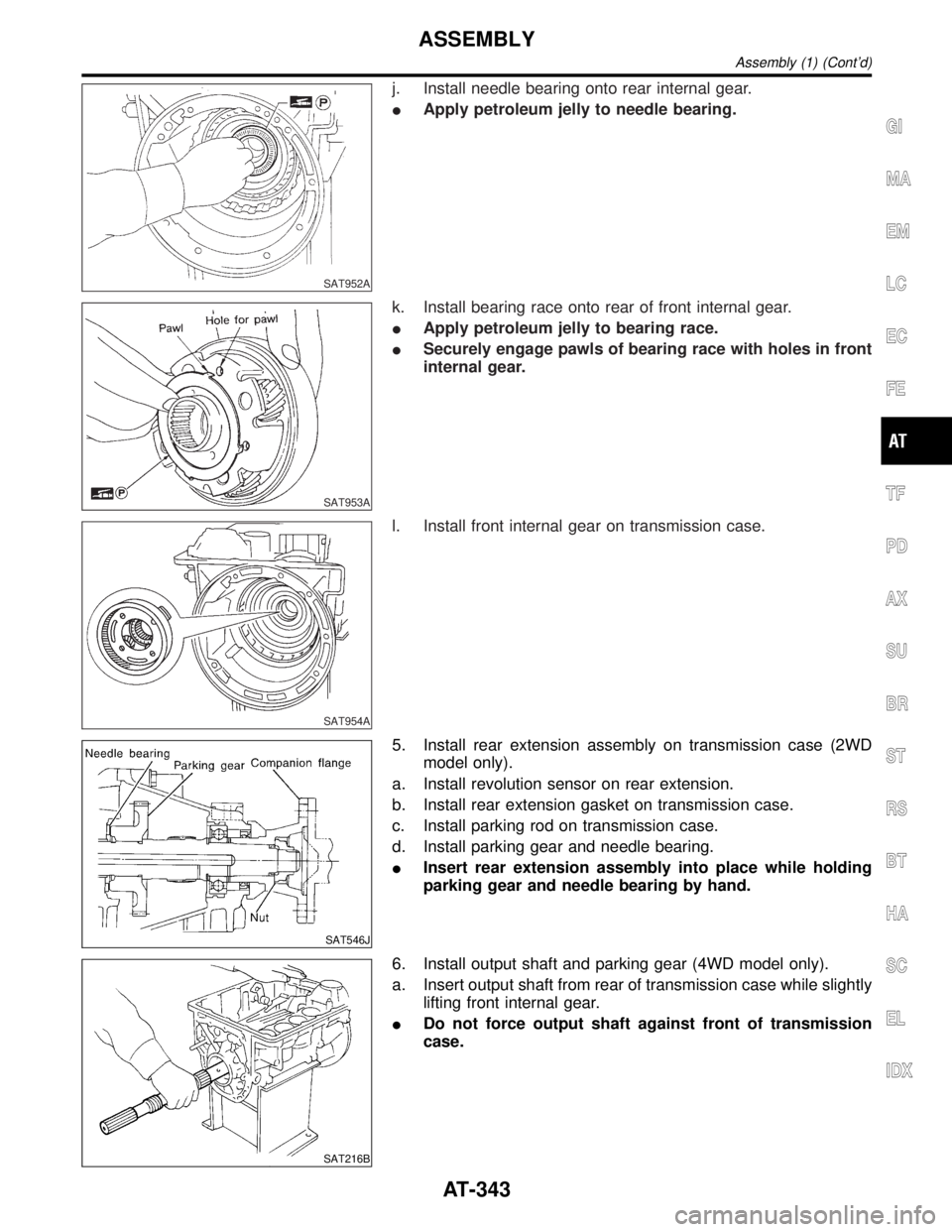
j. Install needle bearing onto rear internal gear.
IApply petroleum jelly to needle bearing.
SAT953A
k. Install bearing race onto rear of front internal gear.
IApply petroleum jelly to bearing race.
ISecurely engage pawls of bearing race with holes in front
internal gear.
SAT954A
l. Install front internal gear on transmission case.
SAT546J
5. Install rear extension assembly on transmission case (2WD
model only).
a. Install revolution sensor on rear extension.
b. Install rear extension gasket on transmission case.
c. Install parking rod on transmission case.
d. Install parking gear and needle bearing.
IInsert rear extension assembly into place while holding
parking gear and needle bearing by hand.
SAT216B
6. Install output shaft and parking gear (4WD model only).
a. Insert output shaft from rear of transmission case while slightly
lifting front internal gear.
IDo not force output shaft against front of transmission
case.
GI
MA
EM
LC
EC
FE
TF
PD
AX
SU
BR
ST
RS
BT
HA
SC
EL
IDX
ASSEMBLY
Assembly (1) (Cont'd)
AT-343
Page 378 of 2395
SFA236
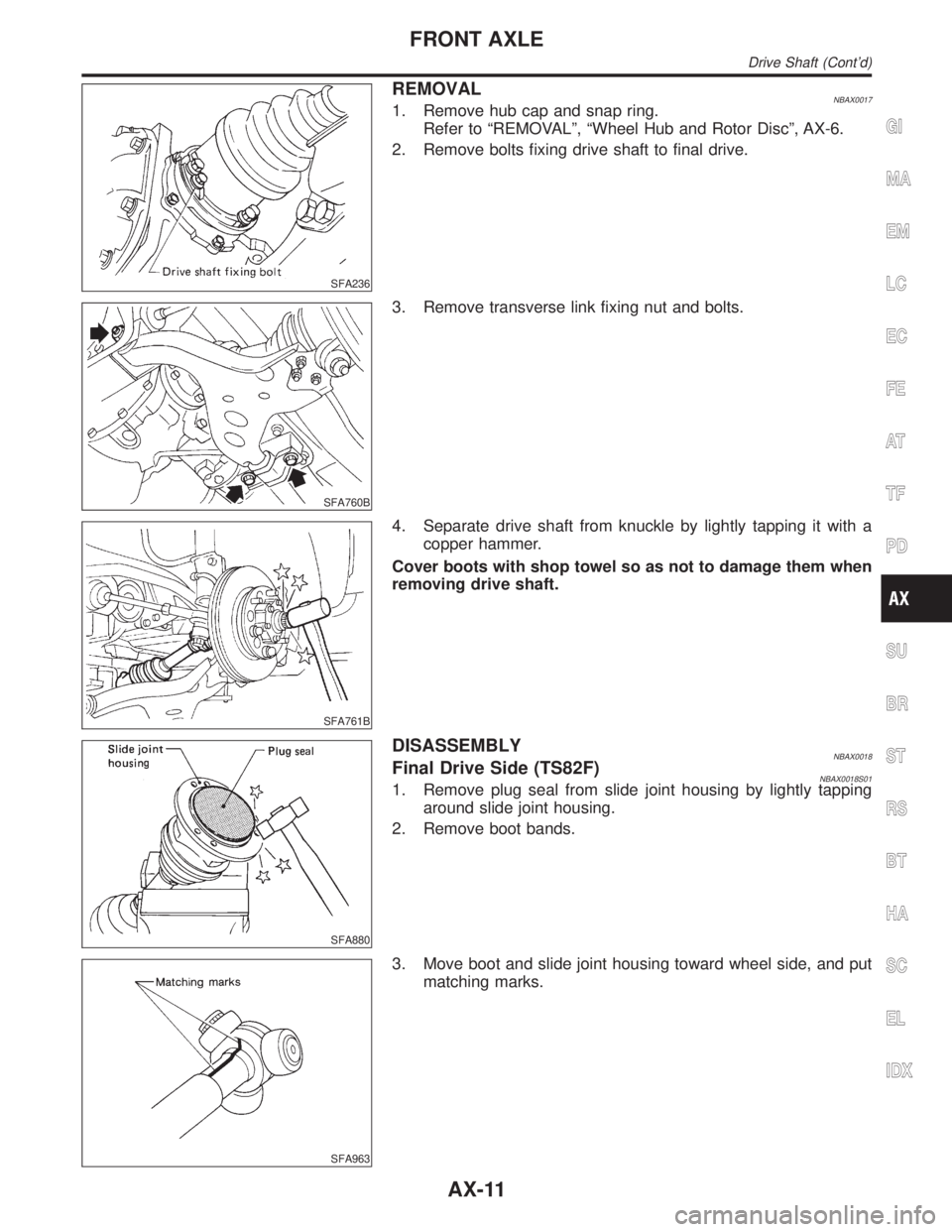
REMOVALNBAX00171. Remove hub cap and snap ring.
Refer to ªREMOVALº, ªWheel Hub and Rotor Discº, AX-6.
2. Remove bolts fixing drive shaft to final drive.
SFA760B
3. Remove transverse link fixing nut and bolts.
SFA761B
4. Separate drive shaft from knuckle by lightly tapping it with a
copper hammer.
Cover boots with shop towel so as not to damage them when
removing drive shaft.
SFA880
DISASSEMBLYNBAX0018Final Drive Side (TS82F)NBAX0018S011. Remove plug seal from slide joint housing by lightly tapping
around slide joint housing.
2. Remove boot bands.
SFA963
3. Move boot and slide joint housing toward wheel side, and put
matching marks.
GI
MA
EM
LC
EC
FE
AT
TF
PD
SU
BR
ST
RS
BT
HA
SC
EL
IDX
FRONT AXLE
Drive Shaft (Cont'd)
AX-11