tensioner INFINITI QX4 2001 Factory User Guide
[x] Cancel search | Manufacturer: INFINITI, Model Year: 2001, Model line: QX4, Model: INFINITI QX4 2001Pages: 2395, PDF Size: 43.2 MB
Page 1652 of 2395

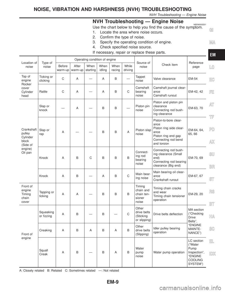
NVH Troubleshooting Ð Engine NoiseNBEM0005S01Use the chart below to help you find the cause of the symptom.
1. Locate the area where noise occurs.
2. Confirm the type of noise.
3. Specify the operating condition of engine.
4. Check specified noise source.
If necessary, repair or replace these parts.
Location of
noiseType of
noiseOperating condition of engine
Source of
noiseCheck itemReference
page Before
warm-upAfter
warm-upWhen
startingWhen
idlingWhen
racingWhile
driving
To p o f
engine
Rocker
cover
Cylinder
headTicking or
clickingC A ÐA BÐTappet
noiseValve clearance EM-54
Rattle C A Ð A B CCamshaft
bearing
noiseCamshaft journal clear-
ance
Camshaft runoutEM-42, 42
Crankshaft
pulley
Cylinder
block
(Side of
engine)
Oil panSlap or
knockÐ A ÐB BÐPiston pin
noisePiston and piston pin
clearance
Connecting rod bush-
ing clearanceEM-63, 70
Slap or
rapA ÐÐBBAPiston slap
noisePiston-to-bore clear-
ance
Piston ring side clear-
ance
Piston ring end gap
Connecting rod bend
and torsionEM-64, 64,
65, 66
Knock A B C B B BConnect-
ing rod
bearing
noiseConnecting rod bush-
ing clearance (Small
end)
Connecting rod bearing
clearance (Big end)EM-70, 69
Knock A B Ð A B CMain bear-
ing noiseMain bearing oil clear-
ance
Crankshaft runoutEM-67, 67
Front of
engine
Timing
chain
coverTapping or
tickingA A ÐBBBTiming
chain and
chain ten-
sioner
noiseTiming chain cracks
and wear
Timing chain tensioner
operationEM-29, 20
Front of
engineSqueaking
or fizzingA B ÐBÐCOther
drive belts
(Sticking
or slipping)Drive belts deflectionMA section
(ªChecking
Drive
Beltsº,
ªENGINE
MAINTE-
NANCEº) Creaking A BABABOther
drive belts
(Slipping)Idler pulley bearing
operation
Squall
CreakA B ÐBABWater
pump
noiseWater pump operationLC section
(ªWater
Pump
Inspectionº,
ªENGINE
COOLING
SYSTEMº)
A: Closely related B: Related C: Sometimes related Ð: Not related
GI
MA
LC
EC
FE
AT
TF
PD
AX
SU
BR
ST
RS
BT
HA
SC
EL
IDX
NOISE, VIBRATION AND HARSHNESS (NVH) TROUBLESHOOTING
NVH Troubleshooting Ð Engine Noise
EM-9
Page 1663 of 2395

ComponentsNBEM0011
JEM410G
1. Rear timing chain case
2. Left camshaft chain tensioner
3. Internal guide
4. Timing chain (Secondary)
5. Right camshaft chain tensioner
6. Timing chain tensioner
7. Slack guide
8. Timing chain (Primary)9. Crankshaft sprocket
10. Lower tension guide
11. Upper tension guide
12. Front timing chain case
13. Crankshaft pulley
14. Water pump cover
15. Chain tensioner cover
16. Exhaust camshaft sprocket17. CVTC cover
18. Intake camshaft sprocket
19. PHASE sensor
20. CVTC sensor
21. Variable induction air control valve
control solenoid valve
22. Swirl control valve control solenoid
valve
TIMING CHAIN
Components
EM-20
Page 1666 of 2395

CAUTION:
IAfter removing timing chain, do not turn crankshaft and
camshaft separately, or valves will strike piston heads.
IWhen installing camshafts, chain tensioners, oil seals, or
other sliding parts, lubricate contacting surfaces with new
engine oil.
IApply new engine oil to bolt threads and seat surfaces
when installing camshaft sprockets and crankshaft pulley.
IBefore disconnecting fuel hose, release fuel pressure.
Refer to EC-39, ªFuel Pressure Releaseº.
IBe careful not to damage sensor edges.
IDo not spill engine coolant on drive belts.
RemovalNBEM00121. Release fuel pressure.
Refer to EC-39, ªFuel Pressure Releaseº.
2. Remove battery.
3. Remove radiator.
Refer to LC-19, ªREMOVAL AND INSTALLATIONº.
4. Drain engine oil.
5. Remove drive belts and idler pulley with brackets.
6. Remove cooling fan with bracket.
7. Remove engine cover.
8. Remove air duct with air cleaner case, collector, blow-by hose,
vacuum hoses, fuel hoses, water hoses, wires, harnesses,
connectors and so on.
9. Remove the air compressor, and tie it down using rope or the
like to keep it from interfering.
10. Remove the power steering oil pump and reservoir tank. Tie
them down using rope or the like to keep them from interfer-
ing.
11. Remove alternator.
12. Remove the following.
IVacuum gallery
IWater bypass pipe
IBrackets
GI
MA
LC
EC
FE
AT
TF
PD
AX
SU
BR
ST
RS
BT
HA
SC
EL
IDX
TIMING CHAIN
Components (Cont'd)
EM-23
Page 1670 of 2395

SEM919EA
30. Remove internal chain guide.
31. Remove upper tension guide.
32. Remove timing chain tensioner and slack guide.
SEM966F
IRemove timing chain tensioner. (Push piston and insert a suit-
able pin into pinhole.)
SEM425G
33. Attach a suitable stopper pin to RH and LH camshaft chain
tensioners.
SEM426G
34. Remove intake and exhaust camshaft sprocket bolts.
IApply paint to timing chain and camshaft sprockets for
alignment during installation.
ISecure the hexagonal head of the camshaft using a span-
ner to loosen mounting bolts.
GI
MA
LC
EC
FE
AT
TF
PD
AX
SU
BR
ST
RS
BT
HA
SC
EL
IDX
TIMING CHAIN
Removal (Cont'd)
EM-27
Page 1672 of 2395

SEM928E
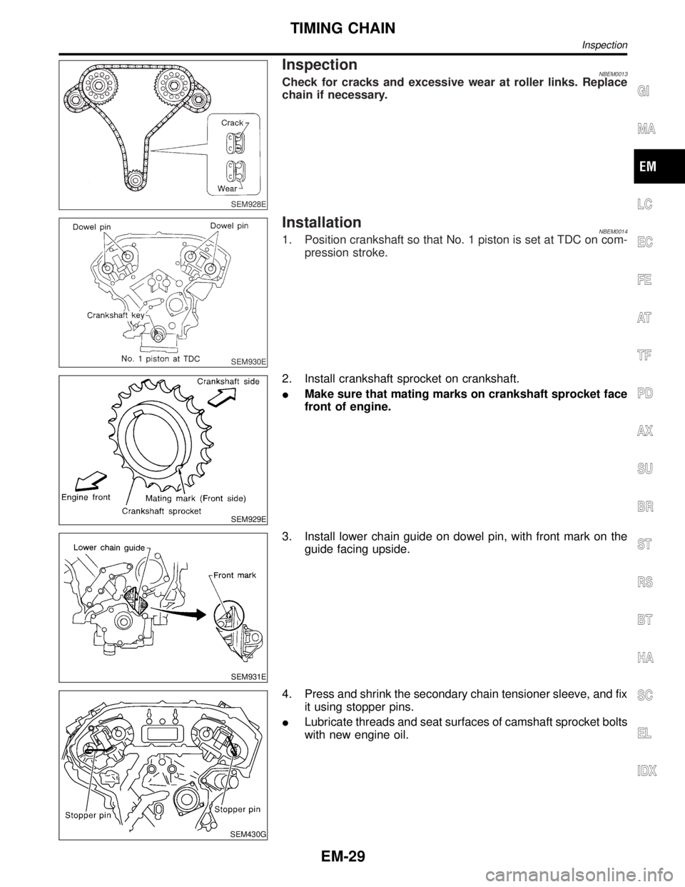
InspectionNBEM0013Check for cracks and excessive wear at roller links. Replace
chain if necessary.
SEM930E
InstallationNBEM00141. Position crankshaft so that No. 1 piston is set at TDC on com-
pression stroke.
SEM929E
2. Install crankshaft sprocket on crankshaft.
IMake sure that mating marks on crankshaft sprocket face
front of engine.
SEM931E
3. Install lower chain guide on dowel pin, with front mark on the
guide facing upside.
SEM430G
4. Press and shrink the secondary chain tensioner sleeve, and fix
it using stopper pins.
ILubricate threads and seat surfaces of camshaft sprocket bolts
with new engine oil.
GI
MA
LC
EC
FE
AT
TF
PD
AX
SU
BR
ST
RS
BT
HA
SC
EL
IDX
TIMING CHAIN
Inspection
EM-29
Page 1674 of 2395

SEM426G
7. After confirming the mating marks are aligned, tighten the cam-
shaft sprocket mounting bolts.
ISecure the camshaft hexagonal head using a spanner to
tighten mounting bolts.
SEM425G
8. Pull out the stopper pin from the secondary timing chain ten-
sioner.
SEM919EA
9. Install internal guide.
10. Install upper tension guide and slack guide.
SEM967F
11. Install timing chain tensioner, then remove the stopper pin.
IWhen installing the timing chain tensioner, engine oil
should be applied to the oil hole and tensioner.
GI
MA
LC
EC
FE
AT
TF
PD
AX
SU
BR
ST
RS
BT
HA
SC
EL
IDX
TIMING CHAIN
Installation (Cont'd)
EM-31
Page 1676 of 2395

SEM439G
SEM440G
17. Install RH and LH rocker covers.
Rocker cover tightening procedure:
ITighten in numerical order as shown in the figure.
a. Tighten bolts 1 to 10 in that order to 6.9 to 8.8 N´m (0.7 to 0.9
kg-m, 61 to 78 in-lb).
b. Then tighten bolts 1 to 10 as indicated in figure to 6.9 to 8.8
N´m (0.7 to 0.9 kg-m, 61 to 78 in-lb).
18. Hang engine using the right and left side engine slingers with
a suitable hoist.
19. Set a suitable transmission jack under the suspension mem-
ber.
20. Remove right and left side engine mounting nuts.
21. Remove right and left side suspension member bolts.
22. Install aluminum oil pan. Refer to EM-18, ªInstallationº.
23. Set ring gear stopper using the mounting bolt hole.
IBe careful not to damage the signal plate teeth.
SEM417G
24. Install crankshaft pulley to crankshaft.
IAlign pointer with TDC mark on crankshaft pulley.
SEM531G
25. Install crankshaft pulley bolt.
ILubricate thread and seat surface of the bolt with new
engine oil.
a. Tighten to 39 to 49 N´m (4.0 to 5.0 kg-m, 29 to 36 ft-lb).
b. Put a paint mark on the crankshaft pulley.
SEM963E
c. Again tighten by turning 60É to 66É, about the angle from one
hexagon bolt head corner to another.
26. Install camshaft position sensor (PHASE), crankshaft position
sensors (REF)/(POS) and CVTC sensors.
27. Reinstall removed parts in the reverse order of removal.
IWhen installing fuel tube and intake manifold collectors, refer
to EM-12, ªTIGHTENING PROCEDURESº.
IAfter starting engine, keep idling for three minutes. Then
rev engine up to 3,000 rpm under no load to purge air from
the high-pressure chamber of the chain tensioners. The
engine may produce a rattling noise. This indicates that
GI
MA
LC
EC
FE
AT
TF
PD
AX
SU
BR
ST
RS
BT
HA
SC
EL
IDX
TIMING CHAIN
Installation (Cont'd)
EM-33
Page 1681 of 2395

ComponentsNBEM0016
SEM441GA
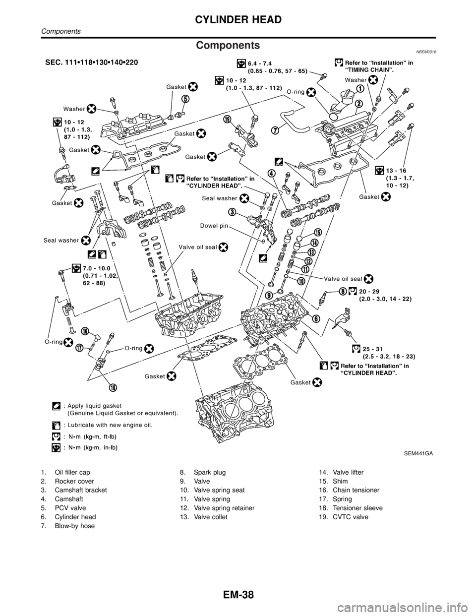
1. Oil filler cap
2. Rocker cover
3. Camshaft bracket
4. Camshaft
5. PCV valve
6. Cylinder head
7. Blow-by hose8. Spark plug
9. Valve
10. Valve spring seat
11. Valve spring
12. Valve spring retainer
13. Valve collet14. Valve lifter
15. Shim
16. Chain tensioner
17. Spring
18. Tensioner sleeve
19. CVTC valve
CYLINDER HEAD
Components
EM-38
Page 1682 of 2395

CAUTION:
IWhen installing camshafts, chain tensioners, oil seals, or
other sliding parts, lubricate contacting surfaces with new
engine oil.
IApply new engine oil to threads and seat surfaces when
installing cylinder head, camshaft sprocket, crankshaft
pulley, and camshaft bracket.
IAttach tags to valve lifters so as not to mix them up.
RemovalNBEM00171. Remove engine from vehicle. Refer to EM-57, ªRemoval and
Installationº.
2. Remove exhaust manifolds in reverse order of installation.
Refer to EM-13, ªExhaust Manifoldº.
3. Place engine on a work stand.
4. Remove aluminum oil pan. Refer to EM-15, ªRemovalº.
5. Remove timing chain. Refer to EM-23, ªRemovalº.
SEM964F
6. Remove intake manifold in reverse order of installation. Refer
to ªTIGHTENING PROCEDURESº, EM-12.
7. Remove water outlet.
SEM442G
8. Remove rear timing chain case bolts.
ILoosen in numerical order as shown in the figure.
SEM168FA
9. Remove rear timing chain case.
GI
MA
LC
EC
FE
AT
TF
PD
AX
SU
BR
ST
RS
BT
HA
SC
EL
IDX
CYLINDER HEAD
Components (Cont'd)
EM-39
Page 1684 of 2395

SEM444G
14. Remove RH and LH camshaft chain tensioners from cylinder
head.
SEM859E
SEM860E
15. Remove cylinder head bolts.
ICylinder head bolts should be loosened in two or three
steps.
IA warped or cracked cylinder head could result from
removing in incorrect order.
SEM863E
16. Remove cylinder head.
DisassemblyNBEM0043Remove valve component parts.
Refer to EM-35, ªVALVE OIL SEALº.
ICheck the clearance before removing the valve guide. Refer to
EM-43, ªVALVE GUIDE CLEARANCEº.
GI
MA
LC
EC
FE
AT
TF
PD
AX
SU
BR
ST
RS
BT
HA
SC
EL
IDX
CYLINDER HEAD
Removal (Cont'd)
EM-41