tow INFINITI QX4 2001 Factory User Guide
[x] Cancel search | Manufacturer: INFINITI, Model Year: 2001, Model line: QX4, Model: INFINITI QX4 2001Pages: 2395, PDF Size: 43.2 MB
Page 1690 of 2395
SEM867E
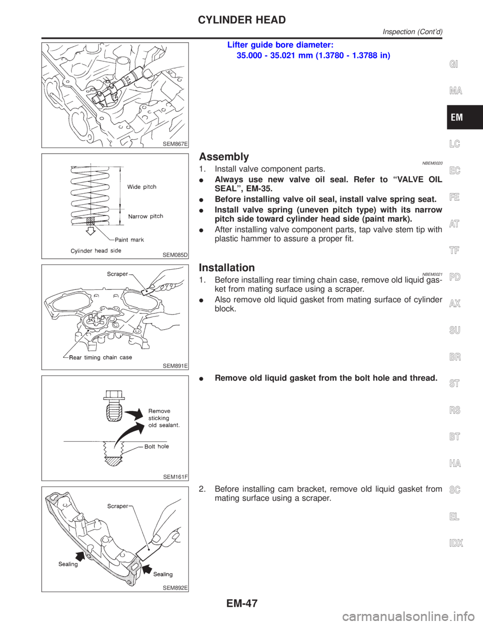
Lifter guide bore diameter:
35.000 - 35.021 mm (1.3780 - 1.3788 in)
SEM085D
AssemblyNBEM00201. Install valve component parts.
IAlways use new valve oil seal. Refer to ªVALVE OIL
SEALº, EM-35.
IBefore installing valve oil seal, install valve spring seat.
IInstall valve spring (uneven pitch type) with its narrow
pitch side toward cylinder head side (paint mark).
IAfter installing valve component parts, tap valve stem tip with
plastic hammer to assure a proper fit.
SEM891E
InstallationNBEM00211. Before installing rear timing chain case, remove old liquid gas-
ket from mating surface using a scraper.
IAlso remove old liquid gasket from mating surface of cylinder
block.
SEM161F
IRemove old liquid gasket from the bolt hole and thread.
SEM892E
2. Before installing cam bracket, remove old liquid gasket from
mating surface using a scraper.
GI
MA
LC
EC
FE
AT
TF
PD
AX
SU
BR
ST
RS
BT
HA
SC
EL
IDX
CYLINDER HEAD
Inspection (Cont'd)
EM-47
Page 1691 of 2395

SEM532G
3. Before installing the cylinder head gasket, be sure that No. 1
cylinder is at TDC.
IAt this time, the crankshaft key should face toward the right
bank.
SEM445G
4. Install cylinder heads with new gaskets.
IDo not rotate crankshaft and camshaft separately, or
valves will strike piston heads.
SEM957E
CAUTION:
Cylinder head bolts are tightened by plastic zone tightening
method. Whenever the size difference between d1 and d2
exceeds the limit, replace them with new ones.
Limit (d1 - d2):
0.11 mm (0.0043 in)
ILubricate threads and seat surfaces of the bolts with new
engine oil.
CYLINDER HEAD
Installation (Cont'd)
EM-48
Page 1698 of 2395
SEM869EA
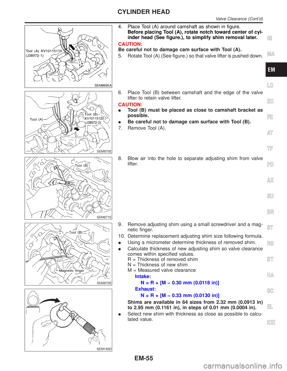
4. Place Tool (A) around camshaft as shown in figure.
Before placing Tool (A), rotate notch toward center of cyl-
inder head (See figure.), to simplify shim removal later.
CAUTION:
Be careful not to damage cam surface with Tool (A).
5. Rotate Tool (A) (See figure.) so that valve lifter is pushed down.
SEM870E
6. Place Tool (B) between camshaft and the edge of the valve
lifter to retain valve lifter.
CAUTION:
ITool (B) must be placed as close to camshaft bracket as
possible.
IBe careful not to damage cam surface with Tool (B).
7. Remove Tool (A).
SEM871E
8. Blow air into the hole to separate adjusting shim from valve
lifter.
SEM872E
SEM145D
9. Remove adjusting shim using a small screwdriver and a mag-
netic finger.
10. Determine replacement adjusting shim size following formula.
IUsing a micrometer determine thickness of removed shim.
ICalculate thickness of new adjusting shim so valve clearance
comes within specified values.
R = Thickness of removed shim
N = Thickness of new shim
M = Measured valve clearance
Intake:
N=R+[Mþ0.30 mm (0.0118 in)]
Exhaust:
N=R+[Mþ0.33 mm (0.0130 in)]
Shims are available in 64 sizes from 2.32 mm (0.0913 in)
to 2.95 mm (0.1161 in), in steps of 0.01 mm (0.0004 in).
ISelect new shim with thickness as close as possible to calcu-
lated value.
GI
MA
LC
EC
FE
AT
TF
PD
AX
SU
BR
ST
RS
BT
HA
SC
EL
IDX
CYLINDER HEAD
Valve Clearance (Cont'd)
EM-55
Page 1700 of 2395
Removal and InstallationNBEM0042WARNING:
ISituate vehicle on a flat and solid surface.
IPlace chocks at front and back of rear wheels.
IDo not remove engine until exhaust system has com-
pletely cooled off. Otherwise, you may burn yourself
and/or fire may break out in fuel line.
IFor safety during subsequent steps, the tension of wires
should be slackened against the engine.
IBefore disconnecting fuel hose, release fuel pressure
from fuel line.
Refer to EC-39, ªFuel Pressure Releaseº.
IBefore removing front axle from transmission, place
safety stands under designated front supporting points.
Refer to GI section for lifting points and towing.
IBe sure to hoist engine and transmission in a safe man-
ner.
IFor engines not equipped with engine slingers, attach
proper slingers and bolts described in PARTS CATALOG.
CAUTION:
IWhen lifting engine, be careful not to strike adjacent parts,
especially accelerator wire casing, brake lines, and brake
master cylinder.
IIn hoisting the engine, always use engine slingers in a
safe manner.
IBefore separating engine and transmission, remove
crankshaft position sensor (POS) from the assembly.
IAlways take extra care not to damage edge of crankshaft
position sensor (POS), or ring gear teeth.GI
MA
LC
EC
FE
AT
TF
PD
AX
SU
BR
ST
RS
BT
HA
SC
EL
IDX
ENGINE ASSEMBLY
Removal and Installation
EM-57
Page 1716 of 2395
SEM455G
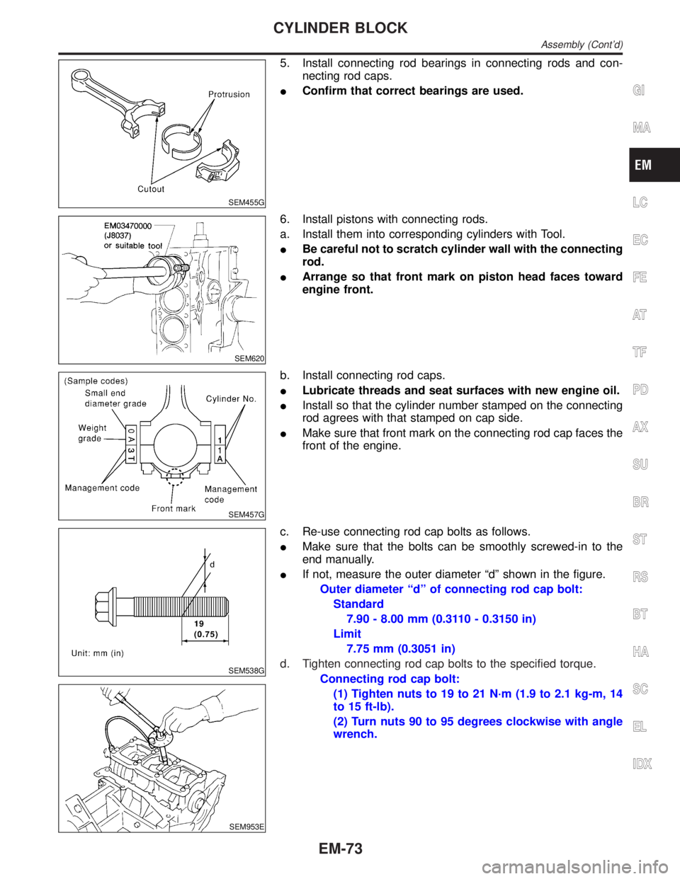
5. Install connecting rod bearings in connecting rods and con-
necting rod caps.
IConfirm that correct bearings are used.
SEM620
6. Install pistons with connecting rods.
a. Install them into corresponding cylinders with Tool.
IBe careful not to scratch cylinder wall with the connecting
rod.
IArrange so that front mark on piston head faces toward
engine front.
SEM457G
b. Install connecting rod caps.
ILubricate threads and seat surfaces with new engine oil.
IInstall so that the cylinder number stamped on the connecting
rod agrees with that stamped on cap side.
IMake sure that front mark on the connecting rod cap faces the
front of the engine.
SEM538G
SEM953E
c. Re-use connecting rod cap bolts as follows.
IMake sure that the bolts can be smoothly screwed-in to the
end manually.
IIf not, measure the outer diameter ªdº shown in the figure.
Outer diameter ªdº of connecting rod cap bolt:
Standard
7.90 - 8.00 mm (0.3110 - 0.3150 in)
Limit
7.75 mm (0.3051 in)
d. Tighten connecting rod cap bolts to the specified torque.
Connecting rod cap bolt:
(1) Tighten nuts to 19 to 21 N´m (1.9 to 2.1 kg-m, 14
to 15 ft-lb).
(2) Turn nuts 90 to 95 degrees clockwise with angle
wrench.
GI
MA
LC
EC
FE
AT
TF
PD
AX
SU
BR
ST
RS
BT
HA
SC
EL
IDX
CYLINDER BLOCK
Assembly (Cont'd)
EM-73
Page 1747 of 2395

Wheels & Tires ..........................................................44
LIFTING POINTS AND TOW TRUCK TOWING...........45
Screw Jack ................................................................45
Garage Jack and Safety Stand .................................46
2-pole Lift ...................................................................47
Tow Truck Towing ......................................................472WD MODELS.........................................................48
4WD MODELS.........................................................48
VEHICLE RECOVERY..............................................49
TIGHTENING TORQUE OF STANDARD BOLTS........50
SAE J1930 TERMINOLOGY LIST................................51
SAE J1930 Terminology List .....................................51
CONTENTS(Cont'd)
GI-2
Page 1790 of 2395

NBGI0008
WARNING:
INever get under the vehicle while it is supported only by
the jack. Always use safety stands to support the frame
when you have to get under the vehicle.
IPlace wheel chocks at both front and back of the wheels
on the ground.
Screw JackNBGI0008S01
SGI927
MA
EM
LC
EC
FE
AT
TF
PD
AX
SU
BR
ST
RS
BT
HA
SC
EL
IDX
LIFTING POINTS AND TOW TRUCK TOWING
GI-45
Page 1791 of 2395

Garage Jack and Safety Stand=NBGI0008S02CAUTION:
Place a wooden or rubber block between safety stand and
vehicle body when the supporting body is flat.
SGI132A
LIFTING POINTS AND TOW TRUCK TOWING
Garage Jack and Safety Stand
GI-46
Page 1792 of 2395
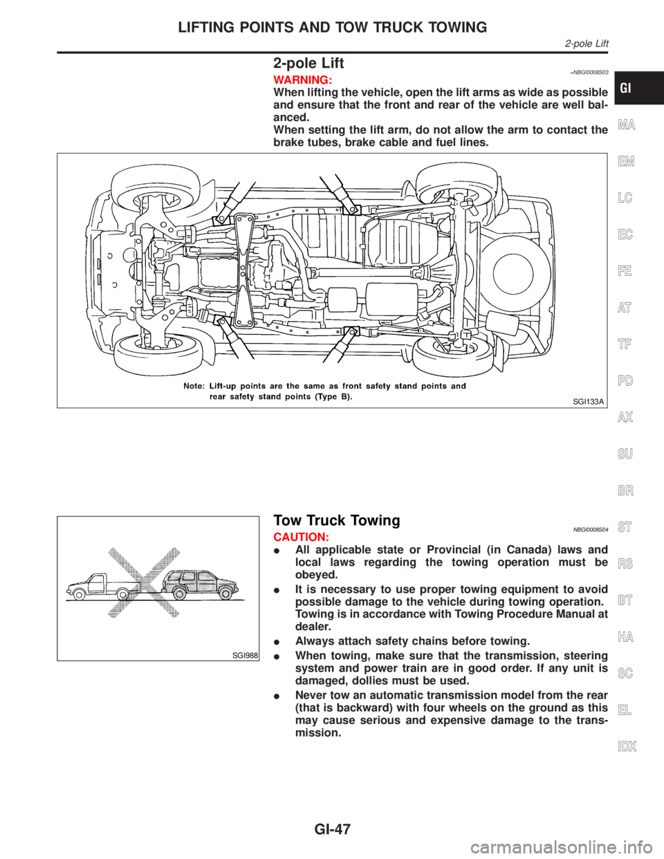
2-pole Lift=NBGI0008S03WARNING:
When lifting the vehicle, open the lift arms as wide as possible
and ensure that the front and rear of the vehicle are well bal-
anced.
When setting the lift arm, do not allow the arm to contact the
brake tubes, brake cable and fuel lines.
SGI133A
SGI988
Tow Truck TowingNBGI0008S04CAUTION:
IAll applicable state or Provincial (in Canada) laws and
local laws regarding the towing operation must be
obeyed.
IIt is necessary to use proper towing equipment to avoid
possible damage to the vehicle during towing operation.
Towing is in accordance with Towing Procedure Manual at
dealer.
IAlways attach safety chains before towing.
IWhen towing, make sure that the transmission, steering
system and power train are in good order. If any unit is
damaged, dollies must be used.
INever tow an automatic transmission model from the rear
(that is backward) with four wheels on the ground as this
may cause serious and expensive damage to the trans-
mission.
MA
EM
LC
EC
FE
AT
TF
PD
AX
SU
BR
ST
RS
BT
HA
SC
EL
IDX
LIFTING POINTS AND TOW TRUCK TOWING
2-pole Lift
GI-47
Page 1793 of 2395

SGI989
2WD MODELSNBGI0008S0402INFINITI recommends that vehicle be towed with the driving (rear)
wheels off the ground as illustrated.
CAUTION:
IWhen towing manual or automatic transmission models
with the front wheels on the ground: Turn the ignition key
to the OFF position and secure the steering wheel in a
straightahead position with a rope or similar device. Never
place the ignition key in the LOCK position. This will result
in damage to the steering lock mechanism.
IWhen towing manual transmission models with the rear
wheels on the ground or four wheels on the ground (if you
do not use towing dollies): Always release the parking
brake and move the transmission shift lever to the N (neu-
tral) position.
Observe the following restricted towing speeds and distances.
Manual transmission models:
ISpeed: Below 95 km/h (60 MPH)
IDistance: Less than 800 km (500 miles)
If the speed or distance must necessarily be greater, remove the
propeller shaft beforehand to prevent damage to the transmission.
SGI950
4WD MODELSNBGI0008S0403INFINITI recommends that a dolly or a flat bed truck be used as
illustrated when towing all-mode 4WD models.
LIFTING POINTS AND TOW TRUCK TOWING
Tow Truck Towing (Cont'd)
GI-48