tow INFINITI QX4 2001 Factory Service Manual
[x] Cancel search | Manufacturer: INFINITI, Model Year: 2001, Model line: QX4, Model: INFINITI QX4 2001Pages: 2395, PDF Size: 43.2 MB
Page 12 of 2395
SEF291H
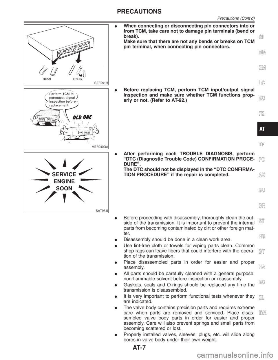
IWhen connecting or disconnecting pin connectors into or
from TCM, take care not to damage pin terminals (bend or
break).
Make sure that there are not any bends or breaks on TCM
pin terminal, when connecting pin connectors.
MEF040DA
IBefore replacing TCM, perform TCM input/output signal
inspection and make sure whether TCM functions prop-
erly or not. (Refer to AT-92.)
SAT964I
IAfter performing each TROUBLE DIAGNOSIS, perform
ªDTC (Diagnostic Trouble Code) CONFIRMATION PROCE-
DUREº.
The DTC should not be displayed in the ªDTC CONFIRMA-
TION PROCEDUREº if the repair is completed.
IBefore proceeding with disassembly, thoroughly clean the out-
side of the transmission. It is important to prevent the internal
parts from becoming contaminated by dirt or other foreign mat-
ter.
IDisassembly should be done in a clean work area.
IUse lint-free cloth or towels for wiping parts clean. Common
shop rags can leave fibers that could interfere with the opera-
tion of the transmission.
IPlace disassembled parts in order for easier and proper
assembly.
IAll parts should be carefully cleaned with a general purpose,
non-flammable solvent before inspection or reassembly.
IGaskets, seals and O-rings should be replaced any time the
transmission is disassembled.
IIt is very important to perform functional tests whenever they
are indicated.
IThe valve body contains precision parts and requires extreme
care when parts are removed and serviced. Place disas-
sembled valve body parts in order for easier and proper
assembly. Care will also prevent springs and small parts from
becoming scattered or lost.
IProperly installed valves, sleeves, plugs, etc. will slide along
bores in valve body under their own weight.
GI
MA
EM
LC
EC
FE
TF
PD
AX
SU
BR
ST
RS
BT
HA
SC
EL
IDX
PRECAUTIONS
Precautions (Cont'd)
AT-7
Page 281 of 2395
SAT551J
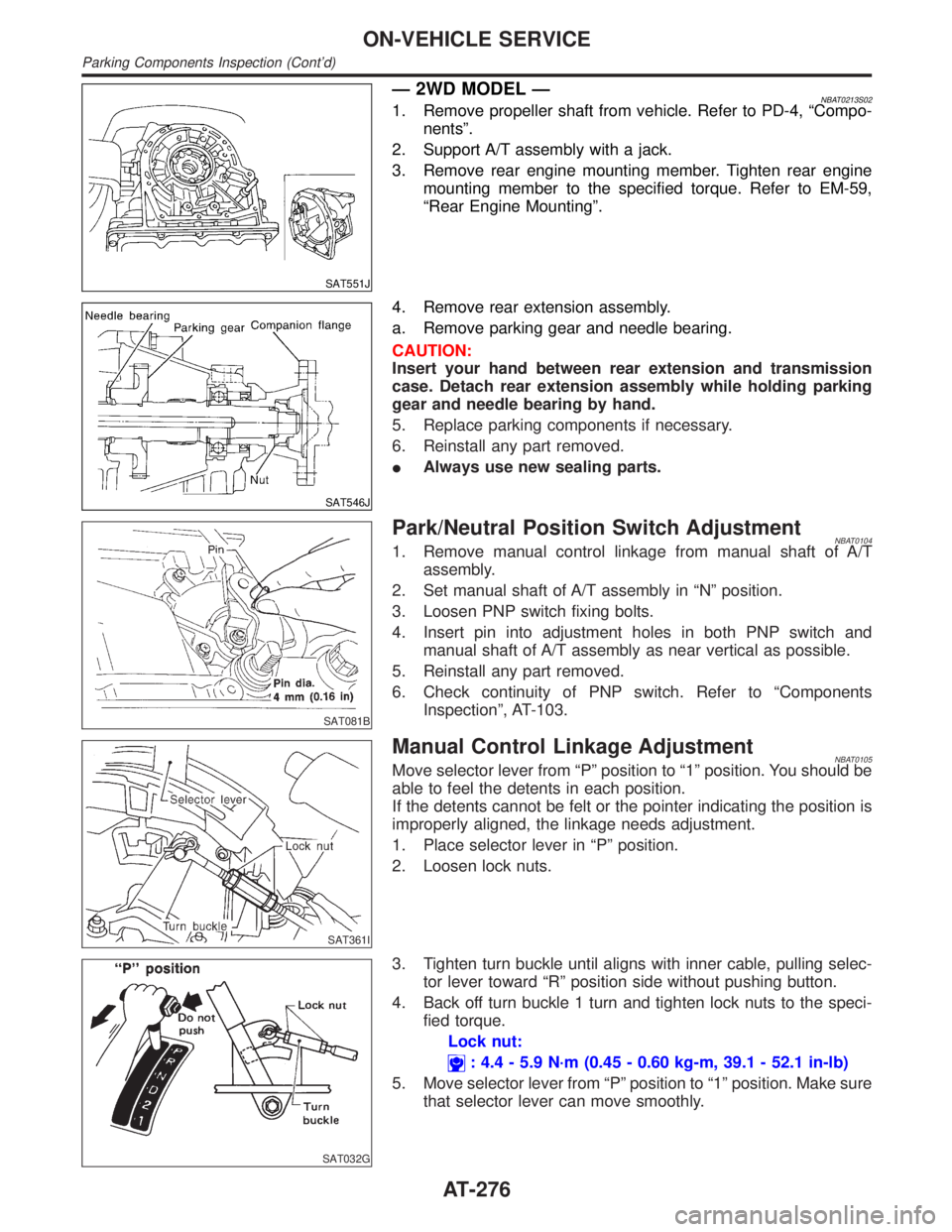
Ð 2WD MODEL ÐNBAT0213S021. Remove propeller shaft from vehicle. Refer to PD-4, ªCompo-
nentsº.
2. Support A/T assembly with a jack.
3. Remove rear engine mounting member. Tighten rear engine
mounting member to the specified torque. Refer to EM-59,
ªRear Engine Mountingº.
SAT546J
4. Remove rear extension assembly.
a. Remove parking gear and needle bearing.
CAUTION:
Insert your hand between rear extension and transmission
case. Detach rear extension assembly while holding parking
gear and needle bearing by hand.
5. Replace parking components if necessary.
6. Reinstall any part removed.
IAlways use new sealing parts.
SAT081B
Park/Neutral Position Switch AdjustmentNBAT01041. Remove manual control linkage from manual shaft of A/T
assembly.
2. Set manual shaft of A/T assembly in ªNº position.
3. Loosen PNP switch fixing bolts.
4. Insert pin into adjustment holes in both PNP switch and
manual shaft of A/T assembly as near vertical as possible.
5. Reinstall any part removed.
6. Check continuity of PNP switch. Refer to ªComponents
Inspectionº, AT-103.
SAT361I
Manual Control Linkage AdjustmentNBAT0105Move selector lever from ªPº position to ª1º position. You should be
able to feel the detents in each position.
If the detents cannot be felt or the pointer indicating the position is
improperly aligned, the linkage needs adjustment.
1. Place selector lever in ªPº position.
2. Loosen lock nuts.
SAT032G
3. Tighten turn buckle until aligns with inner cable, pulling selec-
tor lever toward ªRº position side without pushing button.
4. Back off turn buckle 1 turn and tighten lock nuts to the speci-
fied torque.
Lock nut:
: 4.4 - 5.9 N´m (0.45 - 0.60 kg-m, 39.1 - 52.1 in-lb)
5. Move selector lever from ªPº position to ª1º position. Make sure
that selector lever can move smoothly.
ON-VEHICLE SERVICE
Parking Components Inspection (Cont'd)
AT-276
Page 304 of 2395
SAT657A
SAT658A
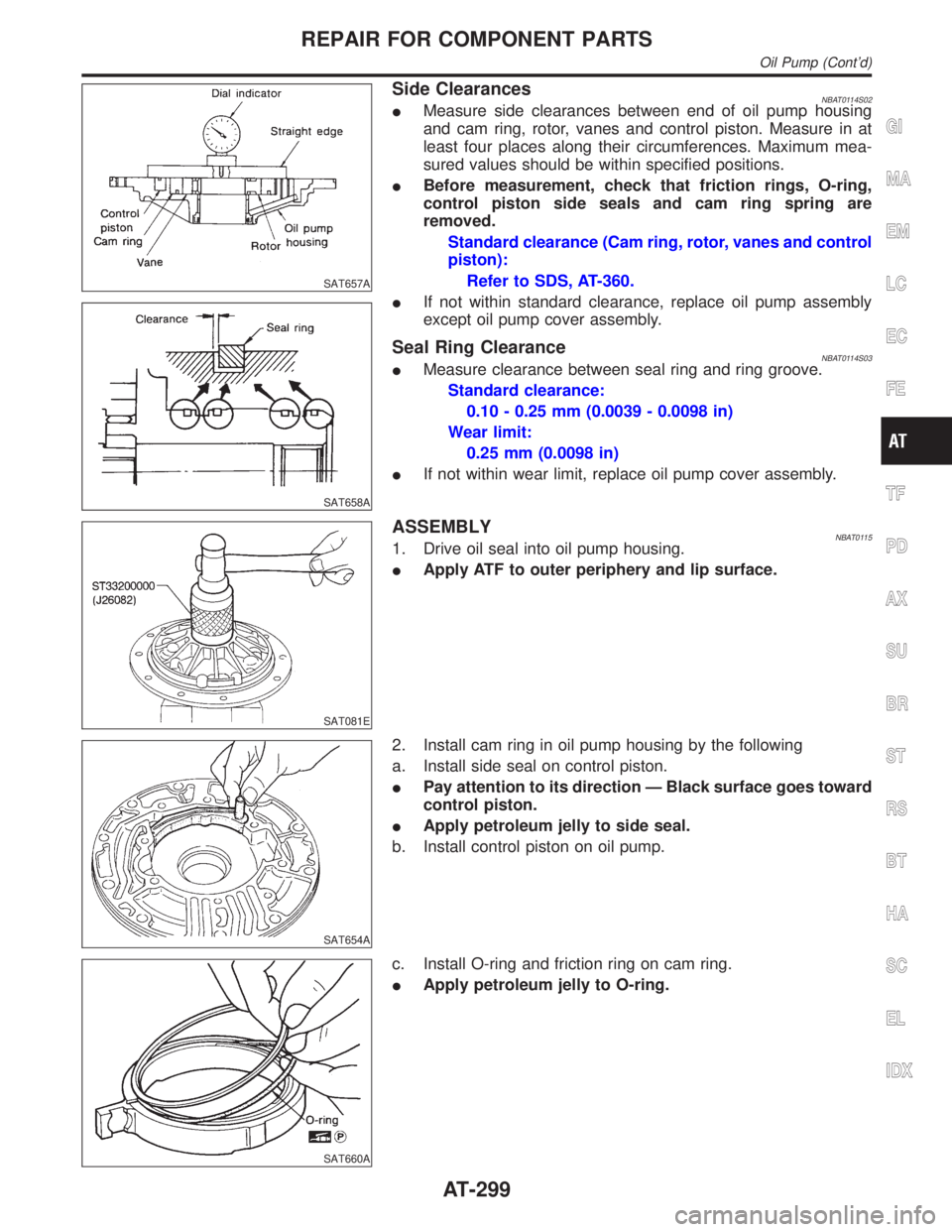
Side ClearancesNBAT0114S02IMeasure side clearances between end of oil pump housing
and cam ring, rotor, vanes and control piston. Measure in at
least four places along their circumferences. Maximum mea-
sured values should be within specified positions.
IBefore measurement, check that friction rings, O-ring,
control piston side seals and cam ring spring are
removed.
Standard clearance (Cam ring, rotor, vanes and control
piston):
Refer to SDS, AT-360.
IIf not within standard clearance, replace oil pump assembly
except oil pump cover assembly.
Seal Ring ClearanceNBAT0114S03IMeasure clearance between seal ring and ring groove.
Standard clearance:
0.10 - 0.25 mm (0.0039 - 0.0098 in)
Wear limit:
0.25 mm (0.0098 in)
IIf not within wear limit, replace oil pump cover assembly.
SAT081E
ASSEMBLYNBAT01151. Drive oil seal into oil pump housing.
IApply ATF to outer periphery and lip surface.
SAT654A
2. Install cam ring in oil pump housing by the following
a. Install side seal on control piston.
IPay attention to its direction Ð Black surface goes toward
control piston.
IApply petroleum jelly to side seal.
b. Install control piston on oil pump.
SAT660A
c. Install O-ring and friction ring on cam ring.
IApply petroleum jelly to O-ring.
GI
MA
EM
LC
EC
FE
TF
PD
AX
SU
BR
ST
RS
BT
HA
SC
EL
IDX
REPAIR FOR COMPONENT PARTS
Oil Pump (Cont'd)
AT-299
Page 378 of 2395
SFA236
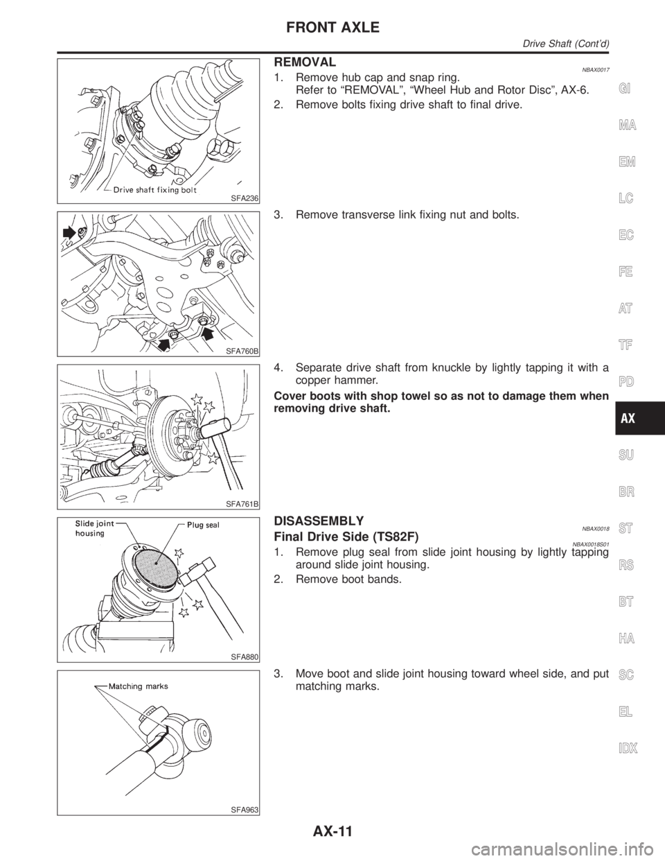
REMOVALNBAX00171. Remove hub cap and snap ring.
Refer to ªREMOVALº, ªWheel Hub and Rotor Discº, AX-6.
2. Remove bolts fixing drive shaft to final drive.
SFA760B
3. Remove transverse link fixing nut and bolts.
SFA761B
4. Separate drive shaft from knuckle by lightly tapping it with a
copper hammer.
Cover boots with shop towel so as not to damage them when
removing drive shaft.
SFA880
DISASSEMBLYNBAX0018Final Drive Side (TS82F)NBAX0018S011. Remove plug seal from slide joint housing by lightly tapping
around slide joint housing.
2. Remove boot bands.
SFA963
3. Move boot and slide joint housing toward wheel side, and put
matching marks.
GI
MA
EM
LC
EC
FE
AT
TF
PD
SU
BR
ST
RS
BT
HA
SC
EL
IDX
FRONT AXLE
Drive Shaft (Cont'd)
AX-11
Page 498 of 2395
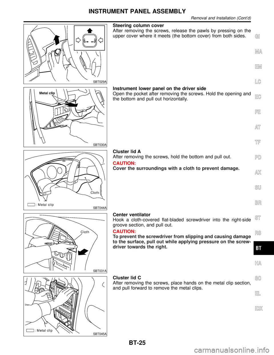
SBT029A
Steering column cover
After removing the screws, release the pawls by pressing on the
upper cover where it meets (the bottom cover) from both sides.
SBT030A
Instrument lower panel on the driver side
Open the pocket after removing the screws. Hold the opening and
the bottom and pull out horizontally.
SBT044A
Cluster lid A
After removing the screws, hold the bottom and pull out.
CAUTION:
Cover the surroundings with a cloth to prevent damage.
SBT031A
Center ventilator
Hook a cloth-covered flat-bladed screwdriver into the right-side
groove section, and pull out.
CAUTION:
To prevent the screwdriver from slipping and causing damage
to the surface, pull out while applying pressure on the screw-
driver towards the right.
SBT045A
Cluster lid C
After removing the screws, place hands on the metal clip section,
and pull forward to remove the metal clips.
GI
MA
EM
LC
EC
FE
AT
TF
PD
AX
SU
BR
ST
RS
HA
SC
EL
IDX
INSTRUMENT PANEL ASSEMBLY
Removal and Installation (Cont'd)
BT-25
Page 499 of 2395

SBT040A
Console finisher
1) Open the lid of the cup holders, insert a cloth-covered flat-
bladed screwdriver into the gap between the console and the
finisher, and remove the clip at the back.
2) Lift up the metal clip section, and pull forward to remove.
SBT033A
Console box
1) Pull up the parking brake lever.
2) Remove the screws, pull the console towards the back of the
car until it is free of the instrument panel, lift up the front and
remove.
IIt will be easier to remove if the parking brake lever is pulled
up for more than 10 notches.
SBT034A
Instrument finisher
Remove the screws and pull up.
SBT046A
Instrument lower panel on the passenger side
After removing the screws, hold both sides and pull out horizontally.
SBT047A
Instrument mask
Insert a cloth-covered flat-bladed screwdriver, and remove by lift-
ing up.
INSTRUMENT PANEL ASSEMBLY
Removal and Installation (Cont'd)
BT-26
Page 622 of 2395
![INFINITI QX4 2001 Factory Service Manual DATA MONITOR MODE=NBEC0034S06
Monitored item [Unit]ECM
input
signalsMain
signalsDescription Remarks
ENG SPEED [rpm]qqIIndicates the engine speed computed
from the REF signal (120É signal) of the
cran INFINITI QX4 2001 Factory Service Manual DATA MONITOR MODE=NBEC0034S06
Monitored item [Unit]ECM
input
signalsMain
signalsDescription Remarks
ENG SPEED [rpm]qqIIndicates the engine speed computed
from the REF signal (120É signal) of the
cran](/img/42/57027/w960_57027-621.png)
DATA MONITOR MODE=NBEC0034S06
Monitored item [Unit]ECM
input
signalsMain
signalsDescription Remarks
ENG SPEED [rpm]qqIIndicates the engine speed computed
from the REF signal (120É signal) of the
crankshaft position sensor (REF).
CKPS´RPM (POS)
[rpm]qIIndicates the engine speed computed
from the POS signal (1É signal) of the
crankshaft position sensor (POS).IAccuracy becomes poor if engine
speed drops below the idle rpm.
IIf the signal is interrupted while the
engine is running, an abnormal value
may be indicated.
POS COUNTqIIndicates the number of signal plate
(Flywheel/Drive Plate) cogs (tooth) dur-
ing one revolution of the engine.
MAS A/F SE-B1 [V]qqIThe signal voltage of the mass air flow
sensor is displayed.IWhen the engine is stopped, a certain
value is indicated.
COOLAN TEMP/S
[ÉC] or [ÉF]qqIThe engine coolant temperature (deter-
mined by the signal voltage of the
engine coolant temperature sensor) is
displayed.IWhen the engine coolant temperature
sensor is open or short-circuited, ECM
enters fail-safe mode. The engine cool-
ant temperature determined by the
ECM is displayed.
HO2S1 (B1) [V]qq
IThe signal voltage of the front heated
oxygen sensor is displayed.
HO2S1 (B2) [V]qq
HO2S2 (B1) [V]qq
IThe signal voltage of the rear heated
oxygen sensor is displayed.
HO2S2 (B2) [V]qq
HO2S1 MNTR (B1)
[RICH/LEAN]qIDisplay of front heated oxygen sensor
signal during air-fuel ratio feedback
control:
RICH ... means the mixture became
ªrichº, and control is being affected
toward a leaner mixture.
LEAN ... means the mixture became
ªleanº, and control is being affected
toward a rich mixture.IAfter turning ON the ignition switch,
ªRICHº is displayed until air-fuel mixture
ratio feedback control begins.
IWhen the air-fuel ratio feedback is
clamped, the value just before the
clamping is displayed continuously. HO2S1 MNTR (B2)
[RICH/LEAN]q
HO2S2 MNTR (B1)
[RICH/LEAN]qIDisplay of rear heated oxygen sensor
signal:
RICH ... means the amount of oxygen
after three way catalyst is relatively
small.
LEAN ... means the amount of oxygen
after three way catalyst is relatively
large.IWhen the engine is stopped, a certain
value is indicated.
HO2S2 MNTR (B2)
[RICH/LEAN]q
VHCL SPEED SE
[km/h] or [mph]qqIThe vehicle speed computed from the
vehicle speed sensor signal is dis-
played.
BATTERY VOLT [V]qqIThe power supply voltage of ECM is
displayed.
THRTL POS SEN [V]qqIThe throttle position sensor signal volt-
age is displayed.
FUEL T/TMP SE
[ÉC] or [ÉF]IThe fuel temperature judged from the
tank fuel temperature sensor signal
voltage is displayed.GI
MA
EM
LC
FE
AT
TF
PD
AX
SU
BR
ST
RS
BT
HA
SC
EL
IDX
ON BOARD DIAGNOSTIC SYSTEM DESCRIPTION
CONSULT-II (Cont'd)
EC-87
Page 1219 of 2395
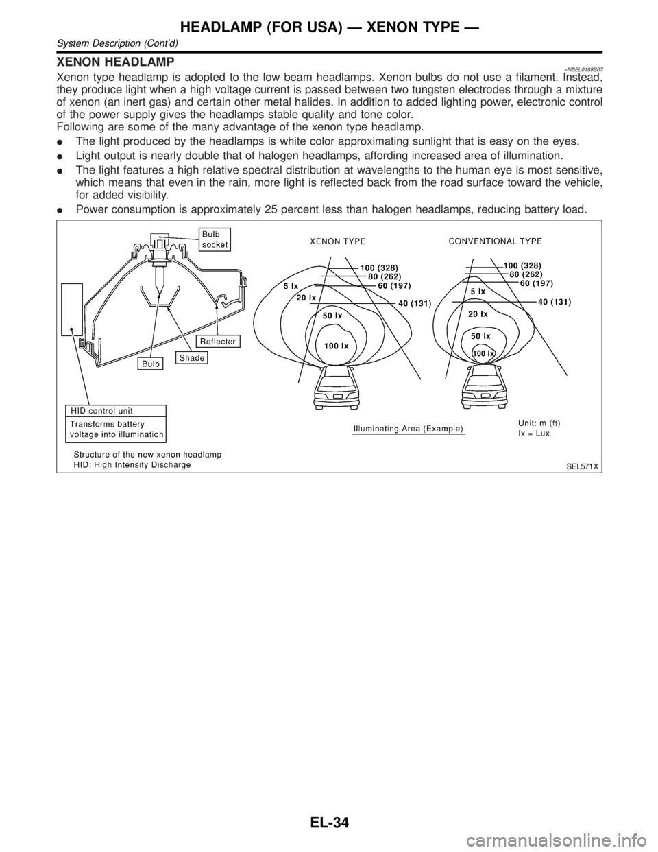
XENON HEADLAMP=NBEL0188S07Xenon type headlamp is adopted to the low beam headlamps. Xenon bulbs do not use a filament. Instead,
they produce light when a high voltage current is passed between two tungsten electrodes through a mixture
of xenon (an inert gas) and certain other metal halides. In addition to added lighting power, electronic control
of the power supply gives the headlamps stable quality and tone color.
Following are some of the many advantage of the xenon type headlamp.
IThe light produced by the headlamps is white color approximating sunlight that is easy on the eyes.
ILight output is nearly double that of halogen headlamps, affording increased area of illumination.
IThe light features a high relative spectral distribution at wavelengths to the human eye is most sensitive,
which means that even in the rain, more light is reflected back from the road surface toward the vehicle,
for added visibility.
IPower consumption is approximately 25 percent less than halogen headlamps, reducing battery load.
SEL571X
HEADLAMP (FOR USA) Ð XENON TYPE Ð
System Description (Cont'd)
EL-34
Page 1357 of 2395
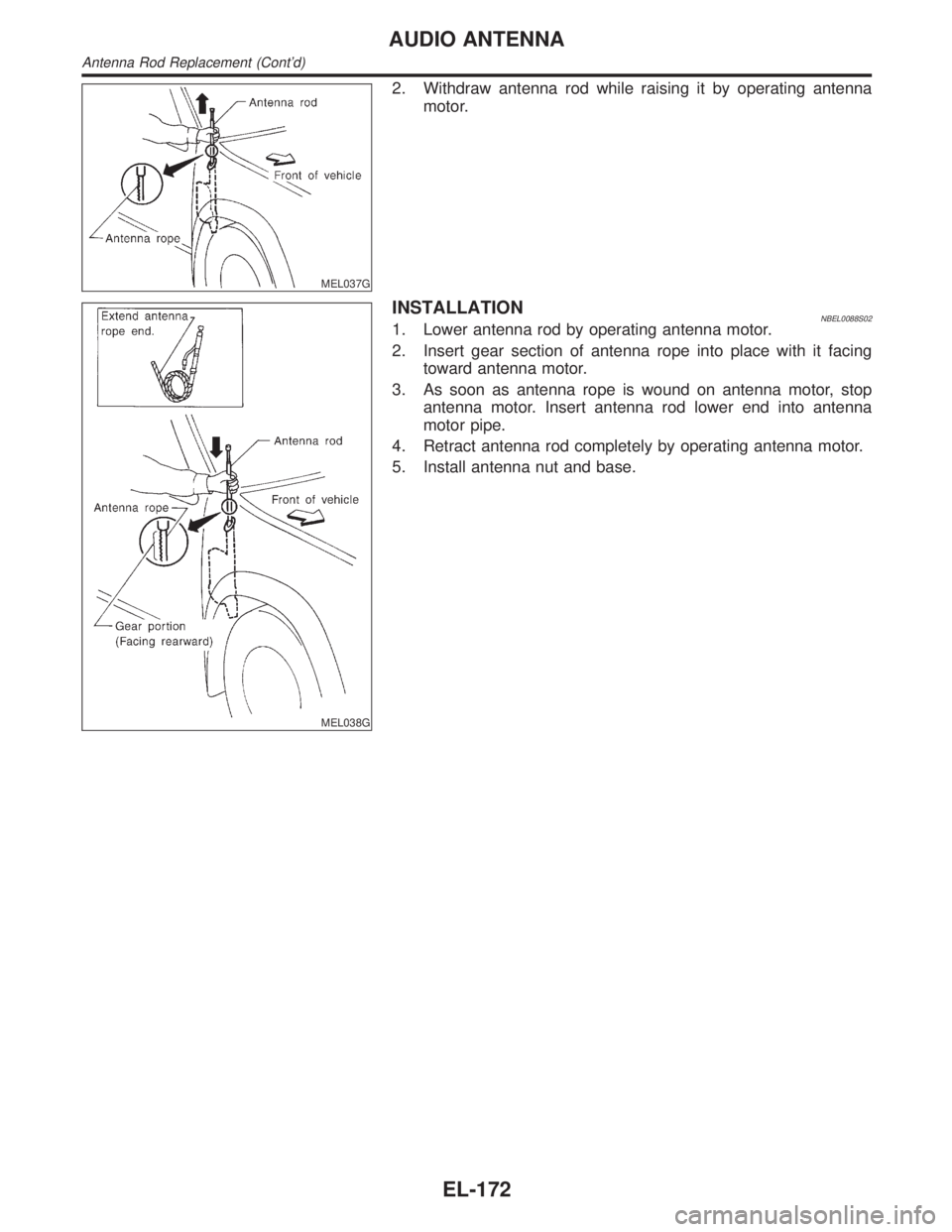
MEL037G
2. Withdraw antenna rod while raising it by operating antenna
motor.
MEL038G
INSTALLATIONNBEL0088S021. Lower antenna rod by operating antenna motor.
2. Insert gear section of antenna rope into place with it facing
toward antenna motor.
3. As soon as antenna rope is wound on antenna motor, stop
antenna motor. Insert antenna rod lower end into antenna
motor pipe.
4. Retract antenna rod completely by operating antenna motor.
5. Install antenna nut and base.
AUDIO ANTENNA
Antenna Rod Replacement (Cont'd)
EL-172
Page 1613 of 2395
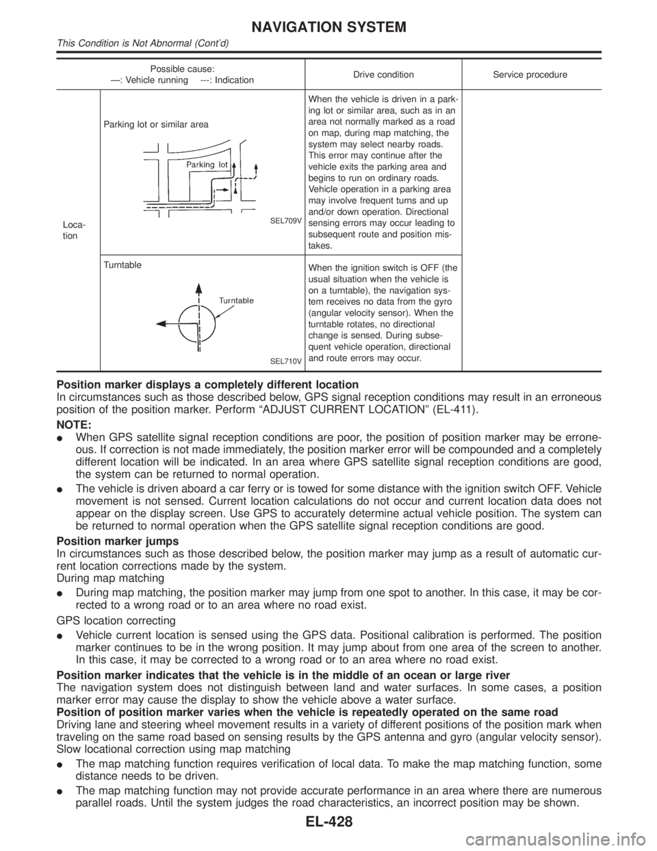
Possible cause:
Ð: Vehicle running ---: IndicationDrive condition Service procedure
Loca-
tionParking lot or similar area
SEL709V
When the vehicle is driven in a park-
ing lot or similar area, such as in an
area not normally marked as a road
on map, during map matching, the
system may select nearby roads.
This error may continue after the
vehicle exits the parking area and
begins to run on ordinary roads.
Vehicle operation in a parking area
may involve frequent turns and up
and/or down operation. Directional
sensing errors may occur leading to
subsequent route and position mis-
takes.
Turntable
SEL710V
When the ignition switch is OFF (the
usual situation when the vehicle is
on a turntable), the navigation sys-
tem receives no data from the gyro
(angular velocity sensor). When the
turntable rotates, no directional
change is sensed. During subse-
quent vehicle operation, directional
and route errors may occur.
Position marker displays a completely different location
In circumstances such as those described below, GPS signal reception conditions may result in an erroneous
position of the position marker. Perform ªADJUST CURRENT LOCATIONº (EL-411).
NOTE:
IWhen GPS satellite signal reception conditions are poor, the position of position marker may be errone-
ous. If correction is not made immediately, the position marker error will be compounded and a completely
different location will be indicated. In an area where GPS satellite signal reception conditions are good,
the system can be returned to normal operation.
IThe vehicle is driven aboard a car ferry or is towed for some distance with the ignition switch OFF. Vehicle
movement is not sensed. Current location calculations do not occur and current location data does not
appear on the display screen. Use GPS to accurately determine actual vehicle position. The system can
be returned to normal operation when the GPS satellite signal reception conditions are good.
Position marker jumps
In circumstances such as those described below, the position marker may jump as a result of automatic cur-
rent location corrections made by the system.
During map matching
IDuring map matching, the position marker may jump from one spot to another. In this case, it may be cor-
rected to a wrong road or to an area where no road exist.
GPS location correcting
IVehicle current location is sensed using the GPS data. Positional calibration is performed. The position
marker continues to be in the wrong position. It may jump about from one area of the screen to another.
In this case, it may be corrected to a wrong road or to an area where no road exist.
Position marker indicates that the vehicle is in the middle of an ocean or large river
The navigation system does not distinguish between land and water surfaces. In some cases, a position
marker error may cause the display to show the vehicle above a water surface.
Position of position marker varies when the vehicle is repeatedly operated on the same road
Driving lane and steering wheel movement results in a variety of different positions of the position mark when
traveling on the same road based on sensing results by the GPS antenna and gyro (angular velocity sensor).
Slow locational correction using map matching
IThe map matching function requires verification of local data. To make the map matching function, some
distance needs to be driven.
IThe map matching function may not provide accurate performance in an area where there are numerous
parallel roads. Until the system judges the road characteristics, an incorrect position may be shown.
NAVIGATION SYSTEM
This Condition is Not Abnormal (Cont'd)
EL-428