wheel bolts INFINITI QX4 2001 Factory User Guide
[x] Cancel search | Manufacturer: INFINITI, Model Year: 2001, Model line: QX4, Model: INFINITI QX4 2001Pages: 2395, PDF Size: 43.2 MB
Page 2073 of 2395

DISASSEMBLYNBPD0036
SPD404A
CAUTION:
Do not run engine when one wheel (rear) is off the ground.
SPD275
1. Remove side bearing inner cone with Tool.
2. Loosen ring gear bolts in a criss-cross pattern.
3. Tap ring gear off gear case with a soft hammer.
Tap evenly all around to keep ring gear from binding.
SPD363A
4. Remove couple bolts on differential cases A and B with a
press.
Tool number: ST33081000 ( Ð )
5. Separate differential case A and B.
Draw out component parts (discs and plates, etc.).
Put marks on gears and pressure rings so that they can be
reinstalled in their original positions from which they were
removed.
REAR FINAL DRIVEH233B
Limited Slip Differential (Cont'd)
PD-48
Page 2092 of 2395

Precautions
SUPPLEMENTAL RESTRAINT SYSTEM (SRS) ªAIR BAGº AND ªSEAT BELT
PRE-TENSIONERº
NBRS0001The Supplemental Restraint System such as ªAIR BAGº and ªSEAT BELT PRE-TENSIONERº used along with
a seat belt, helps to reduce the risk or severity of injury to the driver and front passenger for certain types of
collision. The SRS composition which is available to INFINITI QX4 is as follows:
IFor a frontal collision
The Supplemental Restraint System consists of driver air bag module (located in the center of the steer-
ing wheel), front passenger air bag module (located on the instrument panel on passenger side), seat belt
pre-tensioners, a diagnosis sensor unit, warning lamp, wiring harness and spiral cable.
IFor a side collision
The Supplemental Restraint System consists of side air bag module (located in the outer side of front seat),
satellite sensor, diagnosis sensor unit (one of components of air bags for a frontal collision), wiring harness,
warning lamp (one of components of air bags for a frontal collision).
WARNING:
ITo avoid rendering the SRS inoperative, which could increase the risk of personal injury or death
in the event of a collision which would result in air bag inflation, all maintenance must be performed
by an authorized INFINITI dealer.
IImproper maintenance, including incorrect removal and installation of the SRS, can lead to per-
sonal injury caused by unintentional activation of the system.
IDo not use electrical test equipment on any circuit related to the SRS unless instructed to in this
Service Manual. Spiral cable and wiring harnesses covered with yellow insulation tape either just
before the harness connectors or for the complete harness are related to the SRS.
PRECAUTION FOR SEAT BELT SERVICENBRS0002CAUTION:
IBefore removing the seat belt pre-tensioner assembly, turn the ignition switch off, disconnect both
battery cables and wait at least 3 minutes.
IDo not use electrical test equipment for seat belt pre-tensioner connector.
IAfter replacing or reinstalling seat belt pre-tensioner assembly, or reconnecting seat belt pre-ten-
sioner connector, check the system function. Refer to ªSRS Operation Checkº (RS-38) for details.
IDo not use disassemble buckle or seat belt assembly.
IReplace anchor bolts if they are deformed or worn out.
INever oil tongue and buckle.
IIf any component of seat belt assembly is questionable, do not repair. Replace the whole seat belt
assembly.
IIf webbing is cut, frayed, or damaged, replace seat belt assembly.
IWhen replacing seat belt assembly, use a genuine seat belt assembly.
After A CollisionNBRS0002S01WARNING:
Inspect all seat belt assemblies including retractors and attaching hardware after any collision.
NISSAN recommends that all seat belt assemblies in use during a collision be replaced unless the
collision was minor and the belts show no damage and continue to operate properly. Failure to do so
could result in serious personal injury in an accident. Seat belt assemblies not in use during a colli-
sion should also be replaced if either damage or improper operation is noted. Seat belt pre-tensioner
should be replaced even if the seat belts are not in use during a frontal collision in which the air bags
are deployed.
Replace any seat belt assembly if:
IThe seat belt was in use at the time of a collision (except for minor collisions and the belts, retractors and
buckles show no damage and continue to operate properly).
IThe seat belt was damaged in an accident. (i.e. torn webbing, bent retractor or guide, etc.)
IThe seat belt attaching point was damaged in an accident. Inspect the seat belt attaching area for dam-
age or distortion and repair as necessary before installing a new seat belt assembly.
IAnchor bolts are deformed or worn out.
IThe seat belt pre-tensioner should be replaced even if the seat belts are not in use during the collision in
which the air bags are deployed.
GI
MA
EM
LC
EC
FE
AT
TF
PD
AX
SU
BR
ST
BT
HA
SC
EL
IDX
SEAT BELTS
Precautions
RS-3
Page 2103 of 2395
SRS797-A
Maintenance ItemsNBRS0011CAUTION:
Do not use electrical test equipment to check SRS circuit.
1. Check operation of ªAIR BAGº warning lamp.
After turning ignition key to ªONº position, air bag warning lamp
illuminates. The ªAIR BAGº warning lamp will go off after about
7 seconds if no malfunction is detected. If any of the following
warning lamp conditions occur, immediately check the air bag
or seat belt pre-tensioner system. Refer to RS-38 for details.
IThe ªAIR BAGº warning lamp does not illuminate when the
ignition switch is turned ªONº.
IThe ªAIR BAGº warning lamp does not go off about 7 seconds
after the ignition switch is turned ªONº.
IThe ªAIR BAGº warning lamp blinks after about 7 seconds after
the ignition switch is turned ªONº.
2. Visually check SRS components.
1) Diagnosis sensor unit
ICheck diagnosis sensor unit and bracket for dents, cracks and
deformities.
ICheck connectors for damage, and terminals for deformities.
2) Air bag module and steering wheel
IRemove air bag module from steering wheel, instrument panel
or seatback. Check harness cover and connectors for damage,
terminals for deformities, and harness for binding.
IInstall driver air bag module to steering wheel to check fit or
alignment with the wheel.
ICheck steering wheel for excessive free play.
IInstall passenger air bag module to instrument panel to check
fit or alignment with the instrument panel.
IInstall side air bag module to seatback to check fit and align-
ment with the seat.
3) Spiral cable
ICheck spiral cable for dents, cracks, or deformities.
ICheck connectors and protective tape for damage.
ICheck steering wheel for noise, binding or heavy operation.
4) Main harness, air bag harness, body harness, side air bag
module sub-harness
ICheck connectors for poor connections, damage, and termi-
nals for deformities.
ICheck harnesses for binding, chafing or cut.
5) Seat belt pre-tensioner
ICheck harness cover and connectors for damage, terminals
for deformities, and harness for binding.
ICheck belts for damage and anchors for loose mounting.
ICheck retractor for smooth operation.
IPerform self-diagnosis for seat belt pre-tensioner using air bag
warning lamp or CONSULT-II. Refer to ªSRS Operation Checkº
for details. (RS-38)
6) Satellite sensor
ICheck satellite sensor (including bracket portion) for dents,
cracks or deformities.
ICheck connectors for damage, and terminals for deformities.
CAUTION:
Replace previously used special bolts and ground bolt with
new ones.
SUPPLEMENTAL RESTRAINT SYSTEM (SRS)
Maintenance Items
RS-14
Page 2106 of 2395

Driver Air Bag Module and Spiral Cable
REMOVAL AND INSTALLATIONNBRS0013
SRS782-A
SBF811E
REMOVALNBRS0014CAUTION:
IBefore servicing SRS, turn the ignition switch off, discon-
nect both battery cables and wait at least 3 minutes.
IAlways work from the side of air bag module.
1. Remove lower lid from steering wheel, and disconnect air bag
module connector.
SBF812E
2. Remove side lids, ASCD steering switch and Audio steering
switch (or TEL switch). Using the TAMPER RESISTANT TORX
(Size T50), remove left and right special bolts. Air bag module
can then be removed.
SRS161
CAUTION:
IAlways place air bag module with pad side facing upward.
IDo not attempt to disassemble air bag module.
IThe special bolts are coated with bonding agent. Do not
use old bolts after removal; replace with new ones.
IDo not insert any foreign objects (screwdriver, etc.) into
air bag module connector.
GI
MA
EM
LC
EC
FE
AT
TF
PD
AX
SU
BR
ST
BT
HA
SC
EL
IDX
SUPPLEMENTAL RESTRAINT SYSTEM (SRS)
Driver Air Bag Module and Spiral Cable
RS-17
Page 2108 of 2395
SBF812EH
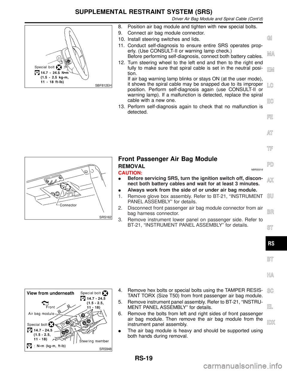
8. Position air bag module and tighten with new special bolts.
9. Connect air bag module connector.
10. Install steering switches and lids.
11. Conduct self-diagnosis to ensure entire SRS operates prop-
erly. (Use CONSULT-II or warning lamp check.)
Before performing self-diagnosis, connect both battery cables.
12. Turn steering wheel to the left end and then to the right end
fully to make sure that spiral cable is set in the neutral posi-
tion.
If air bag warning lamp blinks or stays ON (at the user mode),
it shows the spiral cable may be snapped due to its improper
position. Perform self-diagnosis again (use CONSULT-II or
warning lamp). If a malfunction is detected, replace the spiral
cable with a new one.
13. Perform self-diagnosis again to check that no malfunction is
detected.
SRS162
Front Passenger Air Bag Module
REMOVALNBRS0016CAUTION:
IBefore servicing SRS, turn the ignition switch off, discon-
nect both battery cables and wait for at least 3 minutes.
IAlways work from the side of or under air bag module.
1. Remove glove box assembly. Refer to BT-21, ªINSTRUMENT
PANEL ASSEMBLYº for details.
2. Disconnect front passenger air bag module connector from air
bag harness connector.
3. Remove instrument lower panel on passenger side. Refer to
BT-21, ªINSTRUMENT PANEL ASSEMBLYº for details.
SRS948
4. Remove hex bolts or special bolts using the TAMPER RESIS-
TANT TORX (Size T50) from front passenger air bag module.
5. Remove instrument panel assembly. Refer to BT-21, ªINSTRU-
MENT PANEL ASSEMBLYº for details.
6. Remove the bolts from left and right sides of front passenger
air bag module. Then remove the air bag module from the
instrument panel assembly.
IThe air bag module is heavy and should be supported using
both hands during removal.
GI
MA
EM
LC
EC
FE
AT
TF
PD
AX
SU
BR
ST
BT
HA
SC
EL
IDX
SUPPLEMENTAL RESTRAINT SYSTEM (SRS)
Driver Air Bag Module and Spiral Cable (Cont'd)
RS-19
Page 2148 of 2395
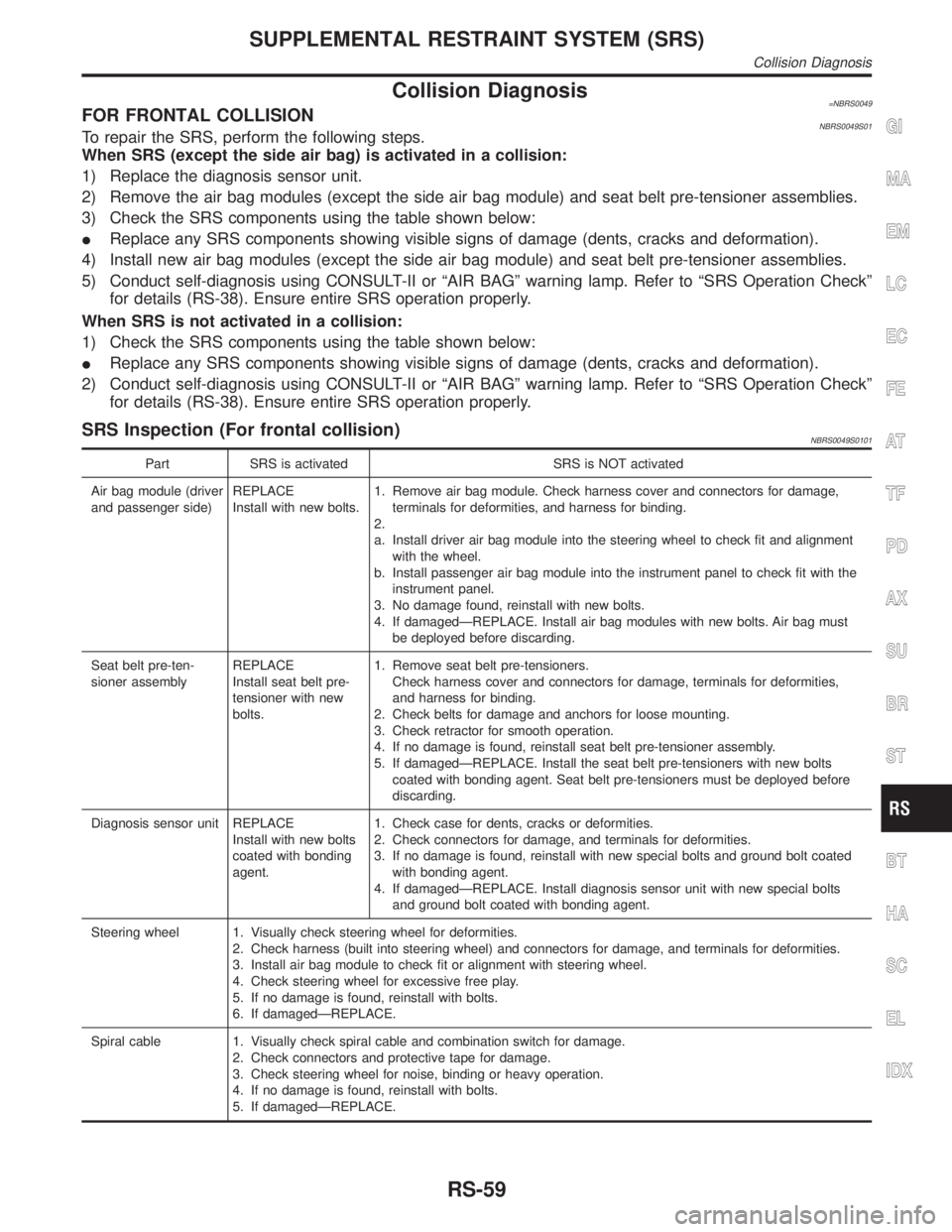
Collision Diagnosis=NBRS0049FOR FRONTAL COLLISIONNBRS0049S01To repair the SRS, perform the following steps.
When SRS (except the side air bag) is activated in a collision:
1) Replace the diagnosis sensor unit.
2) Remove the air bag modules (except the side air bag module) and seat belt pre-tensioner assemblies.
3) Check the SRS components using the table shown below:
IReplace any SRS components showing visible signs of damage (dents, cracks and deformation).
4) Install new air bag modules (except the side air bag module) and seat belt pre-tensioner assemblies.
5) Conduct self-diagnosis using CONSULT-II or ªAIR BAGº warning lamp. Refer to ªSRS Operation Checkº
for details (RS-38). Ensure entire SRS operation properly.
When SRS is not activated in a collision:
1) Check the SRS components using the table shown below:
IReplace any SRS components showing visible signs of damage (dents, cracks and deformation).
2) Conduct self-diagnosis using CONSULT-II or ªAIR BAGº warning lamp. Refer to ªSRS Operation Checkº
for details (RS-38). Ensure entire SRS operation properly.
SRS Inspection (For frontal collision)NBRS0049S0101
Part SRS is activated SRS is NOT activated
Air bag module (driver
and passenger side)REPLACE
Install with new bolts.1. Remove air bag module. Check harness cover and connectors for damage,
terminals for deformities, and harness for binding.
2.
a. Install driver air bag module into the steering wheel to check fit and alignment
with the wheel.
b. Install passenger air bag module into the instrument panel to check fit with the
instrument panel.
3. No damage found, reinstall with new bolts.
4. If damagedÐREPLACE. Install air bag modules with new bolts. Air bag must
be deployed before discarding.
Seat belt pre-ten-
sioner assemblyREPLACE
Install seat belt pre-
tensioner with new
bolts.1. Remove seat belt pre-tensioners.
Check harness cover and connectors for damage, terminals for deformities,
and harness for binding.
2. Check belts for damage and anchors for loose mounting.
3. Check retractor for smooth operation.
4. If no damage is found, reinstall seat belt pre-tensioner assembly.
5. If damagedÐREPLACE. Install the seat belt pre-tensioners with new bolts
coated with bonding agent. Seat belt pre-tensioners must be deployed before
discarding.
Diagnosis sensor unit REPLACE
Install with new bolts
coated with bonding
agent.1. Check case for dents, cracks or deformities.
2. Check connectors for damage, and terminals for deformities.
3. If no damage is found, reinstall with new special bolts and ground bolt coated
with bonding agent.
4. If damagedÐREPLACE. Install diagnosis sensor unit with new special bolts
and ground bolt coated with bonding agent.
Steering wheel 1. Visually check steering wheel for deformities.
2. Check harness (built into steering wheel) and connectors for damage, and terminals for deformities.
3. Install air bag module to check fit or alignment with steering wheel.
4. Check steering wheel for excessive free play.
5. If no damage is found, reinstall with bolts.
6. If damagedÐREPLACE.
Spiral cable 1. Visually check spiral cable and combination switch for damage.
2. Check connectors and protective tape for damage.
3. Check steering wheel for noise, binding or heavy operation.
4. If no damage is found, reinstall with bolts.
5. If damagedÐREPLACE.
GI
MA
EM
LC
EC
FE
AT
TF
PD
AX
SU
BR
ST
BT
HA
SC
EL
IDX
SUPPLEMENTAL RESTRAINT SYSTEM (SRS)
Collision Diagnosis
RS-59
Page 2193 of 2395
SRS266
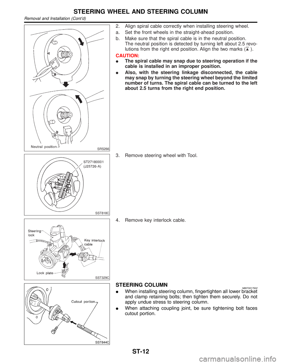
2. Align spiral cable correctly when installing steering wheel.
a. Set the front wheels in the straight-ahead position.
b. Make sure that the spiral cable is in the neutral position.
The neutral position is detected by turning left about 2.5 revo-
lutions from the right end position. Align the two marks (
).
CAUTION:
IThe spiral cable may snap due to steering operation if the
cable is installed in an improper position.
IAlso, with the steering linkage disconnected, the cable
may snap by turning the steering wheel beyond the limited
number of turns. The spiral cable can be turned to the left
about 2.5 turns from the right end position.
SST818C
3. Remove steering wheel with Tool.
SST329C
4. Remove key interlock cable.
SST844C
STEERING COLUMNNBST0017S02IWhen installing steering column, fingertighten all lower bracket
and clamp retaining bolts; then tighten them securely. Do not
apply undue stress to steering column.
IWhen attaching coupling joint, be sure tightening bolt faces
cutout portion.
STEERING WHEEL AND STEERING COLUMN
Removal and Installation (Cont'd)
ST-12
Page 2200 of 2395
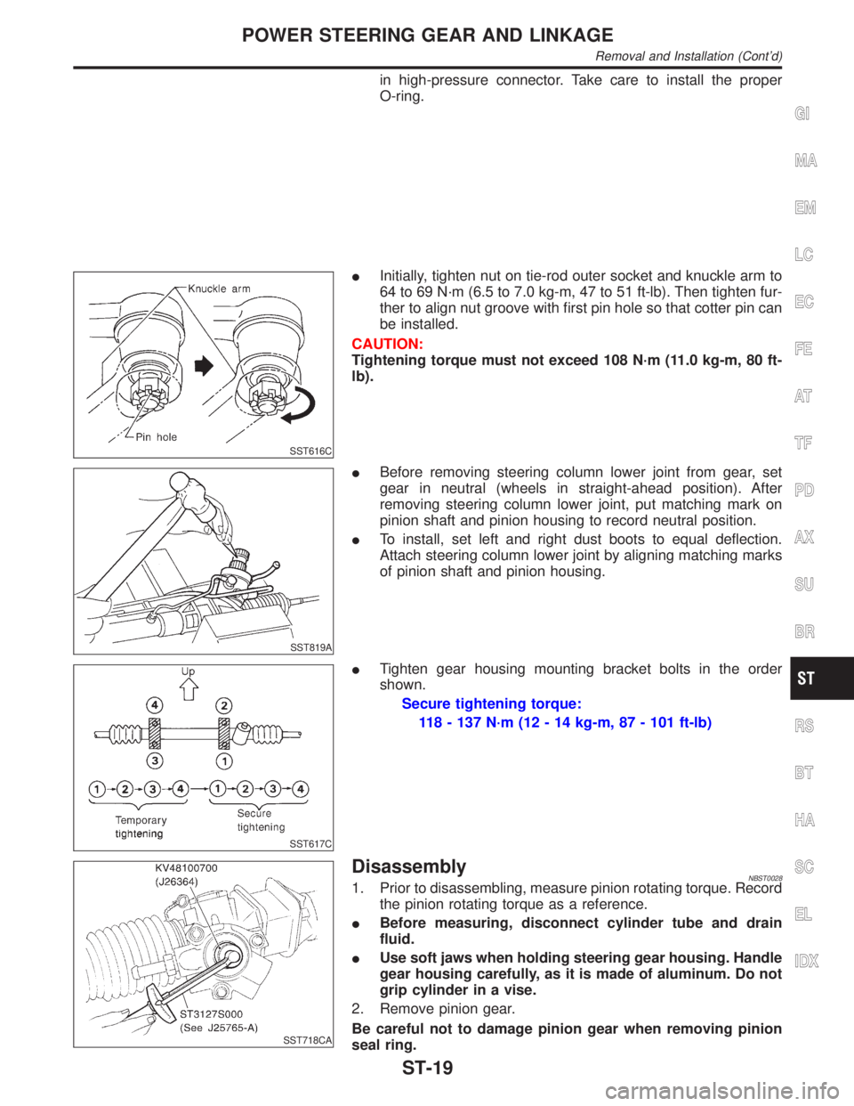
in high-pressure connector. Take care to install the proper
O-ring.
SST616C
IInitially, tighten nut on tie-rod outer socket and knuckle arm to
64 to 69 N´m (6.5 to 7.0 kg-m, 47 to 51 ft-lb). Then tighten fur-
ther to align nut groove with first pin hole so that cotter pin can
be installed.
CAUTION:
Tightening torque must not exceed 108 N´m (11.0 kg-m, 80 ft-
lb).
SST819A
IBefore removing steering column lower joint from gear, set
gear in neutral (wheels in straight-ahead position). After
removing steering column lower joint, put matching mark on
pinion shaft and pinion housing to record neutral position.
ITo install, set left and right dust boots to equal deflection.
Attach steering column lower joint by aligning matching marks
of pinion shaft and pinion housing.
SST617C
ITighten gear housing mounting bracket bolts in the order
shown.
Secure tightening torque:
118 - 137 N´m (12 - 14 kg-m, 87 - 101 ft-lb)
SST718CA
DisassemblyNBST00281. Prior to disassembling, measure pinion rotating torque. Record
the pinion rotating torque as a reference.
IBefore measuring, disconnect cylinder tube and drain
fluid.
IUse soft jaws when holding steering gear housing. Handle
gear housing carefully, as it is made of aluminum. Do not
grip cylinder in a vise.
2. Remove pinion gear.
Be careful not to damage pinion gear when removing pinion
seal ring.
GI
MA
EM
LC
EC
FE
AT
TF
PD
AX
SU
BR
RS
BT
HA
SC
EL
IDX
POWER STEERING GEAR AND LINKAGE
Removal and Installation (Cont'd)
ST-19
Page 2220 of 2395
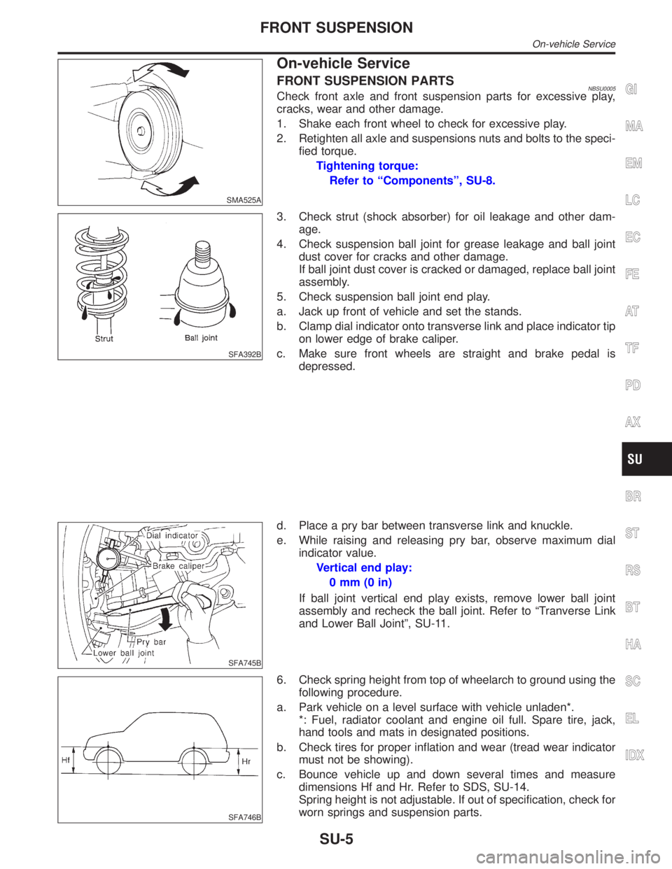
SMA525A
On-vehicle Service
FRONT SUSPENSION PARTSNBSU0005Check front axle and front suspension parts for excessive play,
cracks, wear and other damage.
1. Shake each front wheel to check for excessive play.
2. Retighten all axle and suspensions nuts and bolts to the speci-
fied torque.
Tightening torque:
Refer to ªComponentsº, SU-8.
SFA392B
3. Check strut (shock absorber) for oil leakage and other dam-
age.
4. Check suspension ball joint for grease leakage and ball joint
dust cover for cracks and other damage.
If ball joint dust cover is cracked or damaged, replace ball joint
assembly.
5. Check suspension ball joint end play.
a. Jack up front of vehicle and set the stands.
b. Clamp dial indicator onto transverse link and place indicator tip
on lower edge of brake caliper.
c. Make sure front wheels are straight and brake pedal is
depressed.
SFA745B
d. Place a pry bar between transverse link and knuckle.
e. While raising and releasing pry bar, observe maximum dial
indicator value.
Vertical end play:
0mm(0in)
If ball joint vertical end play exists, remove lower ball joint
assembly and recheck the ball joint. Refer to ªTranverse Link
and Lower Ball Jointº, SU-11.
SFA746B
6. Check spring height from top of wheelarch to ground using the
following procedure.
a. Park vehicle on a level surface with vehicle unladen*.
*: Fuel, radiator coolant and engine oil full. Spare tire, jack,
hand tools and mats in designated positions.
b. Check tires for proper inflation and wear (tread wear indicator
must not be showing).
c. Bounce vehicle up and down several times and measure
dimensions Hf and Hr. Refer to SDS, SU-14.
Spring height is not adjustable. If out of specification, check for
worn springs and suspension parts.
GI
MA
EM
LC
EC
FE
AT
TF
PD
AX
BR
ST
RS
BT
HA
SC
EL
IDX
FRONT SUSPENSION
On-vehicle Service
SU-5
Page 2231 of 2395

ComponentsNBSU0024
SRA880A
SMA525A
On-vehicle Service
REAR SUSPENSION PARTSNBSU0025Check rear axle and rear suspension parts for excessive play, wear
and damage.
1. Shake each rear wheel to check for excessive play.
2. Retighten all nuts and bolts to the specified torque.
Tightening torque: Refer to ªCoil Spring and Shock
Absorberº, SU-18.
SRA754A
3. Check shock absorber for oil leakage and other damage.
4. Check shock absorber bushing for excessive wear and other
damage.
5. Check wheelarch height. Refer to ªOn-vehicle Serviceº,
ªFRONT SUSPENSIONº, SU-5.
REAR SUSPENSION
Components
SU-16