brake light INFINITI QX4 2001 Factory Service Manual
[x] Cancel search | Manufacturer: INFINITI, Model Year: 2001, Model line: QX4, Model: INFINITI QX4 2001Pages: 2395, PDF Size: 43.2 MB
Page 61 of 2395

4. 4-3. Cruise testAT-67
AT-71
Part-1
l8. Vehicle Cannot Be Started From D
1, AT-233.
l9. A/T Does Not Shift: D
1,D2Or Does Not Kickdown: D4,D2, AT-236.
l10. A/T Does Not Shift: D
2,D3, AT-239.
l11. A/T Does Not Shift: D
3,D4, AT-242.
l12. A/T Does Not Perform Lock-up, AT-245.
l13. A/T Does Not Hold Lock-up Condition, AT-247.
l14. Lock-up Is Not Released, AT-249.
l15. Engine Speed Does Not Return To Idle (Light Braking D
4,D3), AT-250.
Part-2AT-75
l16. Vehicle Does Not Start From D
1, AT-252.
l9. A/T Does Not Shift: D
1,D2Or Does Not Kickdown: D4,D2, AT-236.
l10. A/T Does Not Shift: D
2,D3, AT-239.
l11. A/T Does Not Shift: D
3,D4, AT-242.
Part-3AT-77
l17. A/T Does Not Shift: D
4,D3When Overdrive Control Switch ªONº,ªOFFº, AT-253
l15. Engine Speed Does Not Return To Idle (Engine Brake In D
3), AT-250.
l18. A/T Does Not Shift: D
3,22, When Selector Lever ªDº,ª2º Position, AT-254.
l15. Engine Speed Does Not Return To Idle (Engine Brake In 2
2), AT-250.
l19. A/T Does Not Shift: 2
2,11, When Selector Lever ª2º,ª1º Position, AT-255.
l20. Vehicle Does Not Decelerate By Engine Brake, AT-256.
lSELF-DIAGNOSTIC PROCEDURE Ð Mark detected items.
lDTC P0705 PNP switch, AT-99.
lDTC P0710 A/T fluid temperature sensor, AT-105.
lDTC P0720 Vehicle speed sensor´A/T (Revolution sensor), AT-111.
lDTC P0725 Engine speed signal, AT-116.
lDTC P0740 Torque converter clutch solenoid valve, AT-148.
lDTC P0745 Line pressure solenoid valve, AT-162.
lDTC P0750 Shift solenoid valve A, AT-168.
lDTC P0755 Shift solenoid valve B, AT-172.
lDTC P1705 Throttle position sensor, AT-176.
lDTC P1760 Overrun clutch solenoid valve, AT-185.
lDTC BATT/FLUID TEMP SEN (A/T fluid temperature sensor and TCM power source), AT-190.
lDTC Vehicle speed sensor´MTR, AT-197.
lDTC Turbine revolution sensor, AT-202.
lDTC A/T communication line, AT-207.
lDTC Control unit (RAM), control unit (ROM), AT-211.
lDTC Control unit (EEP ROM), AT-213.
lPNP, overdrive control and throttle position switches, AT-257.
lBattery
lOthers
5.lFor self-diagnosis NG items, inspect each component. Repair or replace the damaged parts. AT-38
6.lPerform all ROAD TEST and re-mark required procedures. AT-63
7.lPerform DTC CONFIRMATION PROCEDURE for following MIL indicating items and check out NG items.
Refer to EC-60, ªEmission-related Diagnostic Informationº.EC-60
lDTC (P0731, 1103) A/T 1st gear function, AT-120.
lDTC (P0732, 1104) A/T 2nd gear function, AT-126.
lDTC (P0733, 1105) A/T 3rd gear function, AT-132.
lDTC (P0734, 1106) A/T 4th gear function, AT-138.
lDTC (P0744, 1107) A/T TCC S/V function (lock-up), AT-153.
8.lPerform the Diagnostic Procedures for all remaining items marked NG. Repair or replace the damaged
parts.
Refer to the Symptom Chart when you perform the procedures. (The chart also shows some other possible
symptoms and the component inspection orders.)AT-92
AT-97
9.lErase DTC from TCM and ECM memories. AT-35
TROUBLE DIAGNOSIS Ð INTRODUCTION
Introduction (Cont'd)
AT-56
Page 64 of 2395

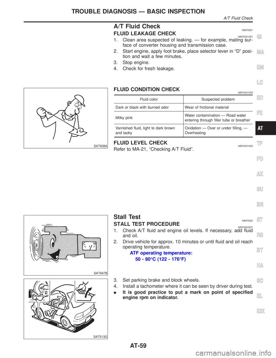
A/T Fluid CheckNBAT0021FLUID LEAKAGE CHECKNBAT0021S011. Clean area suspected of leaking. Ð for example, mating sur-
face of converter housing and transmission case.
2. Start engine, apply foot brake, place selector lever in ªDº posi-
tion and wait a few minutes.
3. Stop engine.
4. Check for fresh leakage.
SAT638A
FLUID CONDITION CHECKNBAT0021S02
Fluid color Suspected problem
Dark or black with burned odor Wear of frictional material
Milky pinkWater contamination Ð Road water
entering through filler tube or breather
Varnished fluid, light to dark brown
and tackyOxidation Ð Over or under filling, Ð
Overheating
FLUID LEVEL CHECKNBAT0021S03Refer to MA-21, ªChecking A/T Fluidº.
SAT647B
Stall TestNBAT0022STALL TEST PROCEDURENBAT0022S011. Check A/T fluid and engine oil levels. If necessary, add fluid
and oil.
2. Drive vehicle for approx. 10 minutes or until fluid and oil reach
operating temperature.
ATF operating temperature:
50 - 80ÉC (122 - 176ÉF)
SAT513G
3. Set parking brake and block wheels.
4. Install a tachometer where it can be seen by driver during test.
IIt is good practice to put a mark on point of specified
engine rpm on indicator.
GI
MA
EM
LC
EC
FE
TF
PD
AX
SU
BR
ST
RS
BT
HA
SC
EL
IDX
TROUBLE DIAGNOSIS Ð BASIC INSPECTION
A/T Fluid Check
AT-59
Page 79 of 2395

7 CHECK LOCK-UP OFF (D4L/U TO D4)
1. Release accelerator pedal.
2. Is lock-up released when accelerator pedal is released?
SAT958I
YesorNo
Ye s©GO TO 8.
No©Go to ª14. Lock-up Is Not Releasedº, AT-249.
8 CHECK SHIFT DOWN (D4TO D3)
1. Decelerate vehicle by applying foot brake lightly.
2. Does engine speed return to idle smoothly when A/T is shifted from D
4to D3?
Read gear position and engine speed.
SAT959I
YesorNo
Ye s©1. Stop vehicle.
2. Go to ªCruise test Ð Part 2º, AT-75.
No©Go to ª15. Engine Speed Does Not Return To Idle (Light Braking D
4,D3)º, AT-250.
TROUBLE DIAGNOSIS Ð BASIC INSPECTION
Road Test (Cont'd)
AT-74
Page 83 of 2395

3 CHECK ENGINE BRAKE
Does vehicle decelerate by engine brake?
SAT999IA
YesorNo
Ye s©GO TO 4.
No©Go to ª15. Engine Speed Does Not Return To Idle (Light Braking D
4,D3)º, AT-250.
4 CHECK SHIFT DOWN (D3TO D2)
1. Move selector lever from ªDº to ª2º position while driving in D3(O/D OFF).
2. Does A/T shift from D
3(O/D OFF) to 22?
Read gear position.
SAT791GB
YesorNo
Ye s©GO TO 5.
No©Go to ª18. A/T Does Not Shift: D
3,D2, When Selector Lever ªDº,ª2º Positionº,
AT-254.
TROUBLE DIAGNOSIS Ð BASIC INSPECTION
Road Test (Cont'd)
AT-78
Page 84 of 2395

5 CHECK ENGINE BRAKE
Does vehicle decelerate by engine brake?
SAT791GB
YesorNo
Ye s©GO TO 6.
No©Go to ª15. Engine Speed Does Not Return To Idle (Light Braking D
4,D3)º, AT-250.
6 CHECK SHIFT DOWN (22TO 11)
1. Move selector lever from ª2º to ª1º position while driving in 22.
2. Does A/T shift from 2
2to 11position?
SAT778B
YesorNo
Ye s©GO TO 7.
No©Go to ª19. A/T Does Not Shift: 2
2,11, When Selector lever ª2º,ª1º Positionº, AT-255.
GI
MA
EM
LC
EC
FE
TF
PD
AX
SU
BR
ST
RS
BT
HA
SC
EL
IDX
TROUBLE DIAGNOSIS Ð BASIC INSPECTION
Road Test (Cont'd)
AT-79
Page 255 of 2395

15. Engine Speed Does Not Return To Idle
(Light Braking D
4®D3)=NBAT0087SYMPTOM:
IEngine speed does not smoothly return to idle when A/T
shifts from D
4to D3.
IVehicle does not decelerate by engine brake when turning
overdrive control switch OFF.
IVehicle does not decelerate by engine brake when shifting
A/T from ªDº to ª2º position.
1 CHECK SELF-DIAGNOSTIC RESULTS
Does self-diagnosis show damage to overrun clutch solenoid valve circuit after cruise test?
SAT583I
YesorNo
Ye s©Check overrun clutch solenoid valve circuit. Refer to ªDTC P1760º, AT-185.
No©GO TO 2.
2 CHECK THROTTLE POSITION SENSOR
Check throttle position sensor. Refer to EC-174, ªDescriptionº.
SAT142K
OK or NG
OK©GO TO 3.
NG©Repair or replace throttle position sensor.
TROUBLE DIAGNOSES FOR SYMPTOMS
15. Engine Speed Does Not Return To Idle (Light Braking D4®D3)
AT-250
Page 261 of 2395

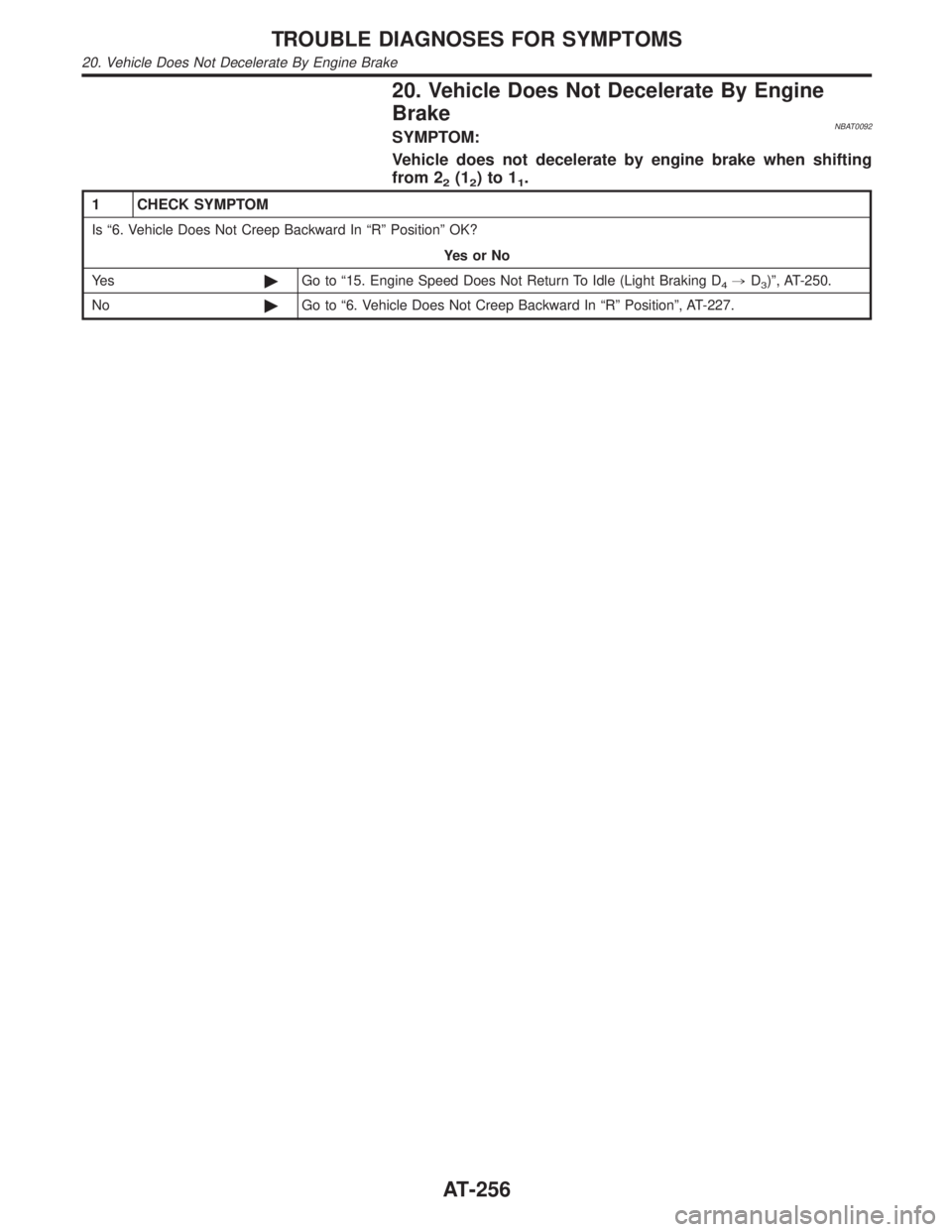
20. Vehicle Does Not Decelerate By Engine
Brake
NBAT0092SYMPTOM:
Vehicle does not decelerate by engine brake when shifting
from 2
2(12)to11.
1 CHECK SYMPTOM
Is ª6. Vehicle Does Not Creep Backward In ªRº Positionº OK?
YesorNo
Ye s©Go to ª15. Engine Speed Does Not Return To Idle (Light Braking D
4,D3)º, AT-250.
No©Go to ª6. Vehicle Does Not Creep Backward In ªRº Positionº, AT-227.
TROUBLE DIAGNOSES FOR SYMPTOMS
20. Vehicle Does Not Decelerate By Engine Brake
AT-256
Page 284 of 2395

SAT017B
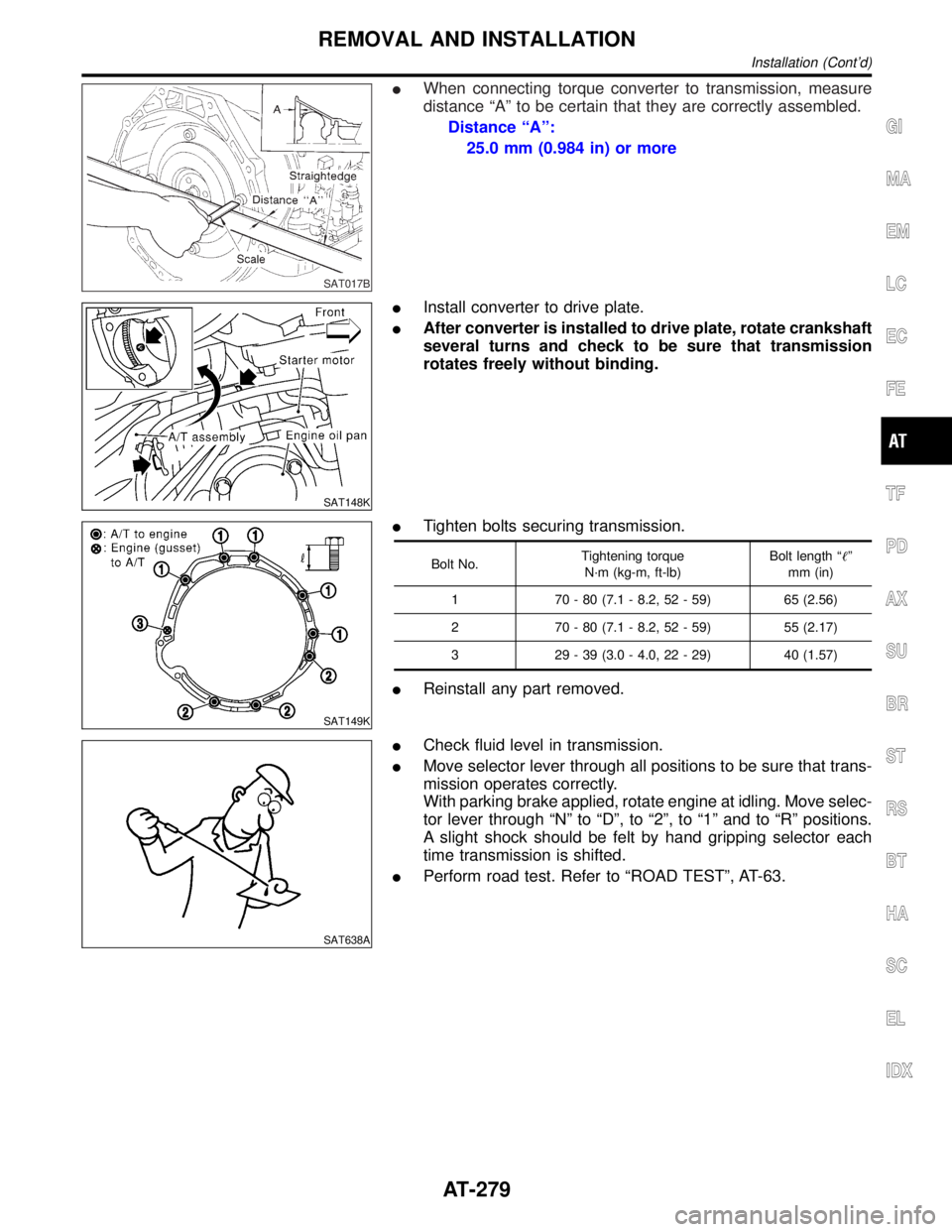
IWhen connecting torque converter to transmission, measure
distance ªAº to be certain that they are correctly assembled.
Distance ªAº:
25.0 mm (0.984 in) or more
SAT148K
IInstall converter to drive plate.
IAfter converter is installed to drive plate, rotate crankshaft
several turns and check to be sure that transmission
rotates freely without binding.
SAT149K
ITighten bolts securing transmission.
Bolt No.Tightening torque
N´m (kg-m, ft-lb)Bolt length ªº
mm (in)
1 70 - 80 (7.1 - 8.2, 52 - 59) 65 (2.56)
2 70 - 80 (7.1 - 8.2, 52 - 59) 55 (2.17)
3 29 - 39 (3.0 - 4.0, 22 - 29) 40 (1.57)
IReinstall any part removed.
SAT638A
ICheck fluid level in transmission.
IMove selector lever through all positions to be sure that trans-
mission operates correctly.
With parking brake applied, rotate engine at idling. Move selec-
tor lever through ªNº to ªDº, to ª2º, to ª1º and to ªRº positions.
A slight shock should be felt by hand gripping selector each
time transmission is shifted.
IPerform road test. Refer to ªROAD TESTº, AT-63.
GI
MA
EM
LC
EC
FE
TF
PD
AX
SU
BR
ST
RS
BT
HA
SC
EL
IDX
REMOVAL AND INSTALLATION
Installation (Cont'd)
AT-279
Page 407 of 2395

ABR190
InstallationNBBR0023CAUTION:
IRefill with new brake fluid ªDOT 3º.
INever reuse drained brake fluid.
1. Place master cylinder onto brake booster and secure mount-
ing nuts lightly.
2. Torque mounting nuts.
: 12 - 15 N´m (1.2 - 1.5 kg-m,9-11ft-lb)
3. Fill up reservoir tank with new brake fluid.
4. Plug all ports on master cylinder with fingers to prevent air
suction while releasing brake pedal.
5. Have driver depress brake pedal slowly several times until no
air comes out of master cylinder.
6. Fit brake lines to master cylinder.
7. Tighten flare nuts.
: 15 - 17 N´m (1.5 - 1.8 kg-m, 11 - 13 ft-lb)
8. Bleed air. Refer to ªBleeding Brake Systemº, BR-8.
MASTER CYLINDER
Installation
BR-18
Page 408 of 2395

SBR002A
SBR365AA
On-vehicle ServiceNBBR0024OPERATING CHECKNBBR0024S011. Depress brake pedal several times with engine off. After
exhausting vacuum, make sure there is no change in pedal
stroke.
2. Depress brake pedal, then start engine. If pedal goes down
slightly, operation is normal.
AIRTIGHT CHECKNBBR0024S021. Start engine, and stop it after one or two minutes. Depress
brake pedal several times slowly. Booster is airtight if pedal
stroke is less each time.
2. Depress brake pedal while engine is running, and stop engine
with pedal depressed. The pedal stroke should not change
after holding pedal down for30 seconds.
SBR368DA
RemovalNBBR0025CAUTION:
IBe careful not to splash brake fluid on painted areas; it
may cause paint damage. If brake fluid is splashed on
painted areas, wash it away with water immediately.
IBe careful not to deform or bend brake pipes, during
removal of booster.
SBR208E
InspectionNBBR0026OUTPUT ROD LENGTH CHECKNBBR0026S011. Apply vacuum of þ66.7 kPa (þ500 mmHg, þ19.69 inHg) to
brake booster with a hand vacuum pump.
2. Add preload of 19.6 N (2.0 kg, 4.4 lb) to output rod.
3. Check output rod length.
Specified length:
10.275 - 10.525 mm (0.4045 - 0.4144 in)
GI
MA
EM
LC
EC
FE
AT
TF
PD
AX
SU
ST
RS
BT
HA
SC
EL
IDX
BRAKE BOOSTER
On-vehicle Service
BR-19