wheels INFINITI QX4 2001 Factory User Guide
[x] Cancel search | Manufacturer: INFINITI, Model Year: 2001, Model line: QX4, Model: INFINITI QX4 2001Pages: 2395, PDF Size: 43.2 MB
Page 700 of 2395

SEF058Y
PROCEDURE FOR MALFUNCTION ANBEC0066S01With CONSULT-IINBEC0066S01011) Turn ignition switch ªONº.
2) Select ªDATA MONITORº mode with CONSULT-II.
3) Wait at least 5 seconds.
4) If 1st trip DTC is detected, go to ªDiagnostic Procedureº,
EC-167.
With GSTNBEC0066S0102Follow the procedure ªWith CONSULT-IIº above.
SEF176Y
PROCEDURE FOR MALFUNCTION BNBEC0066S02CAUTION:
Always drive vehicle at a safe speed.
TESTING CONDITION:
This test may be conducted with the drive wheels lifted in the
shop or by driving the vehicle. If a road test is expected to be
easier, it is unnecessary to lift the vehicle.
With CONSULT-IINBEC0066S02011) Wait until engine coolant temperature is less than 90ÉC
(194ÉF).
a) Turn ignition switch ªONº.
b) Select ªDATA MONITORº mode with CONSULT-II.
c) Check the engine coolant temperature.
d) If the engine coolant temperature is not less than 90ÉC
(194ÉF), turn ignition switch ªOFFº and cool down engine.
IPerform the following steps before engine coolant temperature
is above 90ÉC (194ÉF).
2) Turn ignition switch ªONº.
3) Select ªDATA MONITORº mode with CONSULT-II.
4) Start engine.
5) Hold vehicle speed at more than 70 km/h (43 MPH) for 100
consecutive seconds.
6) If 1st trip DTC is detected, go to ªDiagnostic Procedureº,
EC-167.
With GSTNBEC0066S0202Follow the procedure ªWith CONSULT-IIº above.
GI
MA
EM
LC
FE
AT
TF
PD
AX
SU
BR
ST
RS
BT
HA
SC
EL
IDX
DTC P0110 INTAKE AIR TEMPERATURE SENSOR
DTC Confirmation Procedure (Cont'd)
EC-165
Page 711 of 2395

ICrankshaft position sensor (REF)
ICrankshaft position sensor (POS)
IMass air flow sensor
MALFUNCTION CNBEC0430S03IHarness or connectors
(The throttle position sensor circuit is open or shorted.)
IIntake air leaks
IThrottle position sensor
DTC Confirmation ProcedureNBEC0078NOTE:
IPerform ªPROCEDURE FOR MALFUNCTION Aº first. If the
1st trip DTC cannot be confirmed, perform ªPROCEDURE
FOR MALFUNCTION Bº.
If there is no problem on ªPROCEDURE FOR MALFUNC-
TION Bº, perform ªPROCEDURE FOR MALFUNCTION Cº.
IIf ªDTC Confirmation Procedureº has been previously
conducted, always turn ignition switch ªOFFº and wait at least
10 seconds before conducting the next test.
PROCEDURE FOR MALFUNCTION ANBEC0078S01CAUTION:
Always drive vehicle at a safe speed.
TESTING CONDITION:
IBefore performing the following procedure, confirm that
battery voltage is more than 10V at idle.
IThis test may be conducted with the drive wheels lifted in
the shop or by driving the vehicle. If a road test is
expected to be easier, it is unnecessary to lift the vehicle.
SEF065Y
With CONSULT-IINBEC0078S01011) Turn ignition switch ªONº and select ªDATA MONITORº mode
with CONSULT-II.
2) Start engine and maintain the following conditions for at least
5 consecutive seconds.
Vehicle speed More than 5 km/h (3 MPH)
Selector lever Suitable position except ªPº or ªNº position
3) If 1st trip DTC is detected, go to ªDiagnostic Procedureº,
EC-181.
With GSTNBEC0078S0102Follow the procedure ªWith CONSULT-IIº above.
DTC P0120 THROTTLE POSITION SENSOR
Possible Cause (Cont'd)
EC-176
Page 952 of 2395

AEC110
Component Description=NBEC0242The vehicle speed sensor is installed in the transaxle. It contains a
pulse generator which provides a vehicle speed signal to the
speedometer. The speedometer then sends a signal to the ECM.
ECM Terminals and Reference ValueNBEC0669Specification data are reference values and are measured between each terminal and ground.
CAUTION:
Do not use ECM ground terminals when measuring input/output voltage. Doing so may result in dam-
age to the ECM's transistor. Use a ground other than ECM terminals, such as the ground.
TERMI-
NAL
NO.WIRE
COLORITEM CONDITION DATA (DC Voltage)
86 W/L Vehicle speed sensor[Engine is running]
IJack up front wheels.
IIn 1st gear position
I10 km/h (6 MPH)Approximately 2.5V
SEF583X
[Engine is running]
IJack up front wheels.
IIn 2nd gear position
I30 km/h (19 MPH)Approximately 2.0V
SEF584X
On Board Diagnosis LogicNBEC0244Malfunction is detected when the almost 0 km/h (0 MPH) signal
from vehicle speed sensor is sent to ECM even when vehicle is
being driven.
GI
MA
EM
LC
FE
AT
TF
PD
AX
SU
BR
ST
RS
BT
HA
SC
EL
IDX
DTC P0500 VEHICLE SPEED SENSOR (VSS)
Component Description
EC-417
Page 953 of 2395

Possible CauseNBEC0514IHarness or connector
(The vehicle speed sensor circuit is open or shorted.)
IVehicle speed sensor
DTC Confirmation ProcedureNBEC0245CAUTION:
Always drive vehicle at a safe speed.
NOTE:
If ªDTC Confirmation Procedureº has been previously conducted,
always turn ignition switch ªOFFº and wait at least 10 seconds
before conducting the next test.
TESTING CONDITION:
Steps 1 and 2 may be conducted with the drive wheels lifted
in the shop or by driving the vehicle. If a road test is expected
to be easier, it is unnecessary to lift the vehicle.
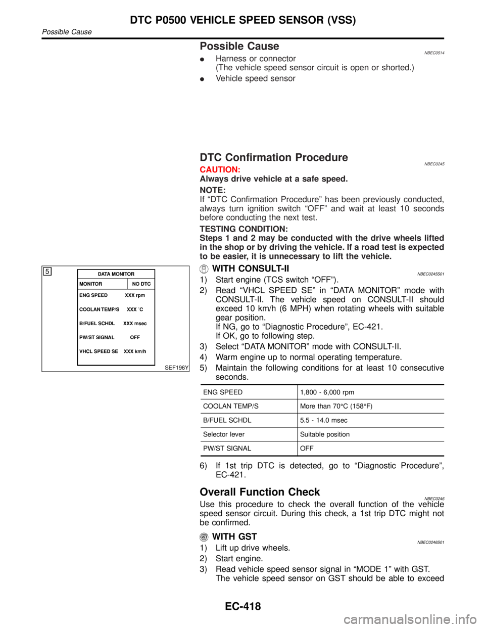
SEF196Y
WITH CONSULT-IINBEC0245S011) Start engine (TCS switch ªOFFº).
2) Read ªVHCL SPEED SEº in ªDATA MONITORº mode with
CONSULT-II. The vehicle speed on CONSULT-II should
exceed 10 km/h (6 MPH) when rotating wheels with suitable
gear position.
If NG, go to ªDiagnostic Procedureº, EC-421.
If OK, go to following step.
3) Select ªDATA MONITORº mode with CONSULT-II.
4) Warm engine up to normal operating temperature.
5) Maintain the following conditions for at least 10 consecutive
seconds.
ENG SPEED 1,800 - 6,000 rpm
COOLAN TEMP/S More than 70ÉC (158ÉF)
B/FUEL SCHDL 5.5 - 14.0 msec
Selector lever Suitable position
PW/ST SIGNAL OFF
6) If 1st trip DTC is detected, go to ªDiagnostic Procedureº,
EC-421.
Overall Function CheckNBEC0246Use this procedure to check the overall function of the vehicle
speed sensor circuit. During this check, a 1st trip DTC might not
be confirmed.
WITH GSTNBEC0246S011) Lift up drive wheels.
2) Start engine.
3) Read vehicle speed sensor signal in ªMODE 1º with GST.
The vehicle speed sensor on GST should be able to exceed
DTC P0500 VEHICLE SPEED SENSOR (VSS)
Possible Cause
EC-418
Page 954 of 2395

10 km/h (6 MPH) when rotating wheels with suitable gear posi-
tion.
4) If NG, go to ªDiagnostic Procedureº, EC-421.
GI
MA
EM
LC
FE
AT
TF
PD
AX
SU
BR
ST
RS
BT
HA
SC
EL
IDX
DTC P0500 VEHICLE SPEED SENSOR (VSS)
Overall Function Check (Cont'd)
EC-419
Page 1098 of 2395

SEF355X
Overall Function CheckNBEC0336Use this procedure to check the overall monitoring function of the
EVAP control system purge flow monitoring. During this check, a
1st trip DTC might not be confirmed.
WITH GSTNBEC0336S011) Lift up drive wheels.
2) Start engine (TCS switch ªOFFº) and warm it up to normal
operating temperature.
3) Turn ignition switch ªOFFº, wait at least 10 seconds.
4) Start engine and wait at least 70 seconds.
5) Set voltmeter probes to ECM terminals 84 (EVAP control sys-
tem pressure sensor signal) and ground.
6) Check EVAP control system pressure sensor value at idle
speed and note it.
7) Establish and maintain the following conditions for at least 1
minute.
Air conditioner switch ON
Steering wheel Fully turned
Headlamp switch ON
Rear window defogger switch ON
Engine speed Approx. 3,000 rpm
Gear position Any position other than ªPº, ªNº or ªRº
8) Verify that EVAP control system pressure sensor value stays
0.1V less than the value at idle speed (measured at step 6) for
at least 1 second.
9) If NG, go to ªDiagnostic Procedureº, EC-564.
GI
MA
EM
LC
FE
AT
TF
PD
AX
SU
BR
ST
RS
BT
HA
SC
EL
IDX
DTC P1447 EVAPORATIVE EMISSION (EVAP) CONTROL SYSTEM PURGE
FLOW MONITORING
Overall Function Check
EC-563
Page 1241 of 2395

Trouble DiagnosesNBEL0193DAYTIME LIGHT CONTROL UNIT INSPECTION TABLENBEL0193S01
Terminal
No.Wire
colorItem ConditionVoltage
(Approximate values)
1 Y/B Alternator
When turning ignition switch to ªONº Less than 1V
When engine is running Battery voltage
When turning ignition switch to ªOFFº Less than 1V
2 Y/R Start signal
When turning ignition switch to ªSTº Battery voltage
When turning ignition switch to ªONº from ªSTº Less than 1V
When turning ignition switch to ªOFFº Less than 1V
3 G Power source
When turning ignition switch to ªONº Battery voltage
When turning ignition switch to ªSTº Battery voltage
When turning ignition switch to ªOFFº Less than 1V
4 R/L Power source
When turning ignition switch to ªONº Battery voltage
When turning ignition switch to ªOFFº Battery voltage
5 R/W Power source
When turning ignition switch to ªONº Battery voltage
When turning ignition switch to ªOFFº Battery voltage
6 R LH hi beam When lighting switch is turned to the 2ND position with
ªHI BEAMº positionBattery voltage
When releasing parking brake with engine running and
turning lighting switch to ªOFFº (daytime light operation)
CAUTION:
Block wheels and ensure selector lever is in N or P
position.Approx. half battery
voltage
HEADLAMP (FOR CANADA) Ð DAYTIME LIGHT SYSTEM Ð
Trouble Diagnoses
EL-56
Page 1242 of 2395

Terminal
No.Wire
colorItem ConditionVoltage
(Approximate values)
7 L/R RH hi beam When lighting switch is turned to the 2ND position with
ªHI BEAMº positionBattery voltage
When releasing parking brake with engine running and
turning lighting switch to ªOFFº (daytime light operation)
CAUTION:
Block wheels and ensure selector lever is in N or P
position.Approx. half battery
voltage
9 PU RH hi beam
(ground)When lighting switch is turned to the 2ND position with
ªHI BEAMº positionLess than 1V
When releasing parking brake with engine running and
turning lighting switch to ªOFFº (daytime light operation)
CAUTION:
Block wheels and ensure selector lever is in N or P
position.Approx. half battery
voltage
10 GY LH hi beam
(ground)When lighting switch is turned to the 2ND position with
ªHI BEAMº positionLess than 1V
When releasing parking brake with engine running and
turning lighting switch to ªOFFº (daytime light operation)
CAUTION:
Block wheels and ensure selector lever is in N or P
position.Approx. half battery
voltage
13
14L/W
W/RLighting switch
(Hi beam)When turning lighting switch to ªHI BEAMº Battery voltage
When turning lighting switch to ªFLASH TO PASSº Battery voltage
16 B Ground Ð Ð
17 L/G Parking brake
switch
When parking brake is released Battery voltage
When parking brake is set Less than 1.5V
BATTERY SAVER CONTROL UNIT INSPECTION TABLENBEL0193S02Refer to ªHEADLAMP (FOR USA)º, EL-42.
Bulb ReplacementNBEL0194Refer to ªHEADLAMP (FOR USA)º (EL-43).
GI
MA
EM
LC
EC
FE
AT
TF
PD
AX
SU
BR
ST
RS
BT
HA
SC
IDX
HEADLAMP (FOR CANADA) Ð DAYTIME LIGHT SYSTEM Ð
Trouble Diagnoses (Cont'd)
EL-57
Page 1421 of 2395

2 CHECK ASCD PUMP CIRCUIT
1. Disconnect ASCD control unit harness connector.
2. Check harness for open or short between ASCD control unit and ASCD pump.
SEL269WB
OK or NG
OK©GO TO 3.
NG©Repair harness.
3 CHECK ASCD PUMP POWER SUPPLY
1. Jack-up the drive wheels.
2. Maintain the conditions below.
IVehicle speed is more than 40 km/h (25 MPH).
IMain switch (CRUISE lamp) is ON.
ISet/coast switch (SET lamp) is ON.
Check voltage between ASCD control unit harness connector terminal 12 and ground.
SEL381WB
OK or NG
OK©ASCD pump power supply is OK.
NG©Replace ASCD control unit.
AUTOMATIC SPEED CONTROL DEVICE (ASCD)
Trouble Diagnoses (Cont'd)
EL-236
Page 1658 of 2395

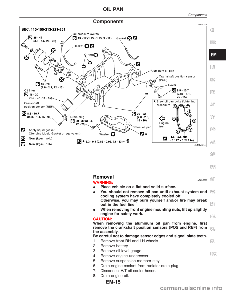
ComponentsNBEM0008
SEM583G
RemovalNBEM0009WARNING:
IPlace vehicle on a flat and solid surface.
IYou should not remove oil pan until exhaust system and
cooling system have completely cooled off.
Otherwise, you may burn yourself and/or fire may break
out in the fuel line.
IWhen removing front engine mounting nuts, lift up slightly
engine for safety work.
CAUTION:
When removing the aluminum oil pan from engine, first
remove the crankshaft position sensors (POS and REF) from
the assembly.
Be careful not to damage sensor edges and signal plate teeth.
1. Remove front RH and LH wheels.
2. Remove battery.
3. Remove oil level gauge.
4. Remove engine undercover.
5. Remove suspension member stay.
6. Drain engine coolant from radiator drain plug.
7. Disconnect A/T oil cooler hoses.
8. Drain engine oil.
GI
MA
LC
EC
FE
AT
TF
PD
AX
SU
BR
ST
RS
BT
HA
SC
EL
IDX
OIL PAN
Components
EM-15