wheels INFINITI QX4 2001 Factory Service Manual
[x] Cancel search | Manufacturer: INFINITI, Model Year: 2001, Model line: QX4, Model: INFINITI QX4 2001Pages: 2395, PDF Size: 43.2 MB
Page 35 of 2395

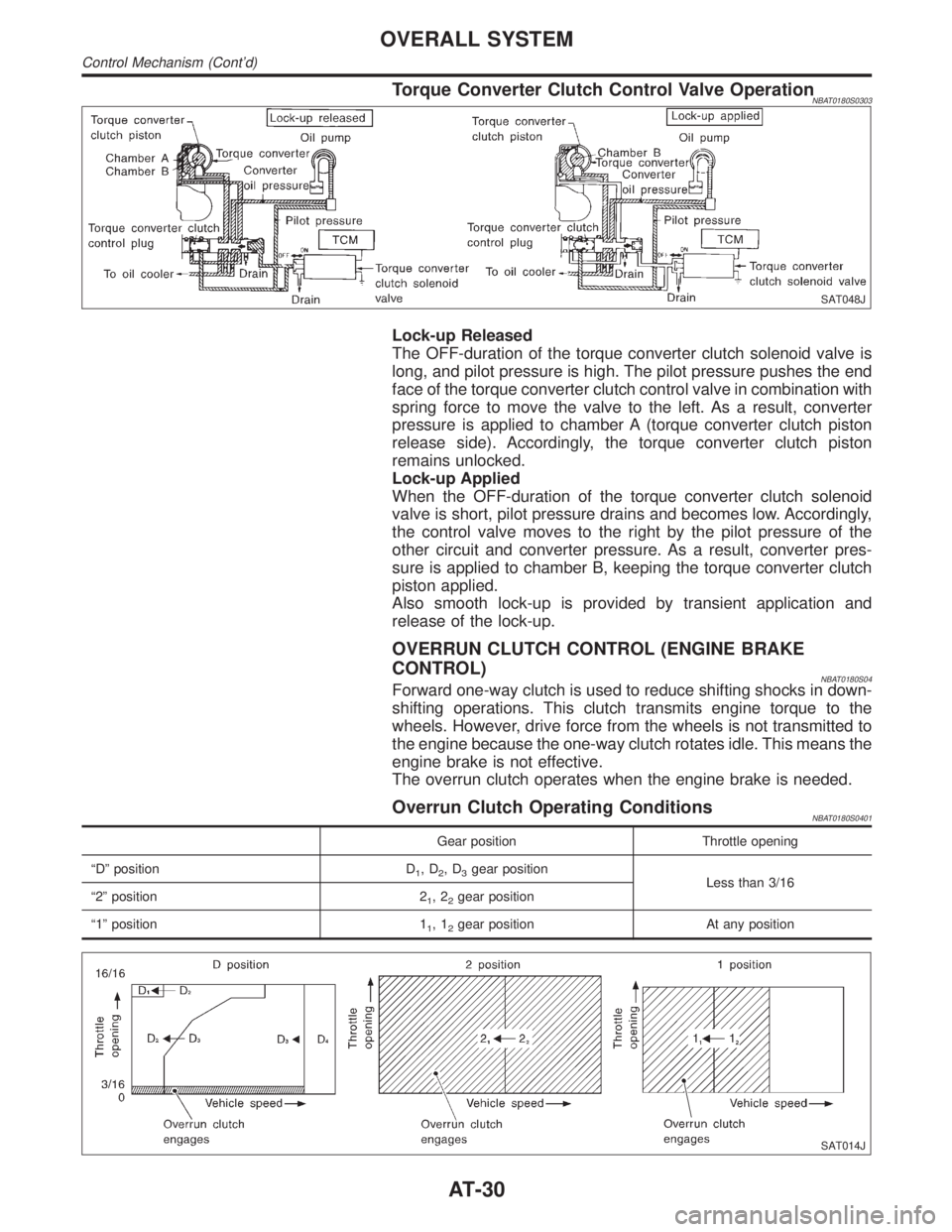
Torque Converter Clutch Control Valve OperationNBAT0180S0303
SAT048J
Lock-up Released
The OFF-duration of the torque converter clutch solenoid valve is
long, and pilot pressure is high. The pilot pressure pushes the end
face of the torque converter clutch control valve in combination with
spring force to move the valve to the left. As a result, converter
pressure is applied to chamber A (torque converter clutch piston
release side). Accordingly, the torque converter clutch piston
remains unlocked.
Lock-up Applied
When the OFF-duration of the torque converter clutch solenoid
valve is short, pilot pressure drains and becomes low. Accordingly,
the control valve moves to the right by the pilot pressure of the
other circuit and converter pressure. As a result, converter pres-
sure is applied to chamber B, keeping the torque converter clutch
piston applied.
Also smooth lock-up is provided by transient application and
release of the lock-up.
OVERRUN CLUTCH CONTROL (ENGINE BRAKE
CONTROL)
NBAT0180S04Forward one-way clutch is used to reduce shifting shocks in down-
shifting operations. This clutch transmits engine torque to the
wheels. However, drive force from the wheels is not transmitted to
the engine because the one-way clutch rotates idle. This means the
engine brake is not effective.
The overrun clutch operates when the engine brake is needed.
Overrun Clutch Operating ConditionsNBAT0180S0401
Gear position Throttle opening
ªDº position D
1,D2,D3gear position
Less than 3/16
ª2º position 2
1,22gear position
ª1º position 1
1,12gear position At any position
SAT014J
OVERALL SYSTEM
Control Mechanism (Cont'd)
AT-30
Page 64 of 2395

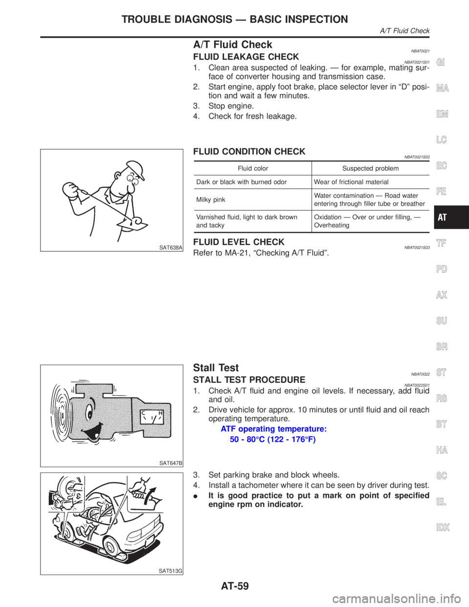
A/T Fluid CheckNBAT0021FLUID LEAKAGE CHECKNBAT0021S011. Clean area suspected of leaking. Ð for example, mating sur-
face of converter housing and transmission case.
2. Start engine, apply foot brake, place selector lever in ªDº posi-
tion and wait a few minutes.
3. Stop engine.
4. Check for fresh leakage.
SAT638A
FLUID CONDITION CHECKNBAT0021S02
Fluid color Suspected problem
Dark or black with burned odor Wear of frictional material
Milky pinkWater contamination Ð Road water
entering through filler tube or breather
Varnished fluid, light to dark brown
and tackyOxidation Ð Over or under filling, Ð
Overheating
FLUID LEVEL CHECKNBAT0021S03Refer to MA-21, ªChecking A/T Fluidº.
SAT647B
Stall TestNBAT0022STALL TEST PROCEDURENBAT0022S011. Check A/T fluid and engine oil levels. If necessary, add fluid
and oil.
2. Drive vehicle for approx. 10 minutes or until fluid and oil reach
operating temperature.
ATF operating temperature:
50 - 80ÉC (122 - 176ÉF)
SAT513G
3. Set parking brake and block wheels.
4. Install a tachometer where it can be seen by driver during test.
IIt is good practice to put a mark on point of specified
engine rpm on indicator.
GI
MA
EM
LC
EC
FE
TF
PD
AX
SU
BR
ST
RS
BT
HA
SC
EL
IDX
TROUBLE DIAGNOSIS Ð BASIC INSPECTION
A/T Fluid Check
AT-59
Page 67 of 2395

SAT209GA
Line Pressure TestNBAT0023ILocation of line pressure test ports.
IAlways replace line pressure plugs as they are self-seal-
ing bolts.
SAT647B
LINE PRESSURE TEST PROCEDURENBAT0023S011. Check A/T fluid and engine oil levels. If necessary, add fluid
and oil.
2. Drive vehicle for approx. 10 minutes or until fluid and oil reach
operating temperature.
ATF operating temperature:
50 - 80ÉC (122 - 176ÉF)
SAT518GB
SAT519GB
3. Install pressure gauge to corresponding line pressure port.
SAT513G
4. Set parking brake and block wheels.
IContinue to depress brake pedal fully while line pressure
test is being performed at stall speed.
TROUBLE DIAGNOSIS Ð BASIC INSPECTION
Line Pressure Test
AT-62
Page 421 of 2395

PurposeNBBR0087The Anti-Lock Brake System (ABS) consists of electronic and hydraulic components. It allows for control of
braking force so locking of the wheels can be avoided.
1) Improves proper tracking performance through steering wheel operation.
2) Eases obstacle avoidance through steering wheel operation.
3) Improves vehicle stability.
OperationNBBR0088IWhen the vehicle speed is less than 10 km/h (6 MPH) this system does not work.
IThe Anti-Lock Brake System (ABS) has a self-test function. The system turns on the ABS warning lamp
for 1 second each time the ignition switch is turned ªONº. After the engine is started, the ABS warning lamp
turns off. The system performs a test the first time the vehicle reaches 6 km/h (4 MPH). A mechanical noise
may be heard as the ABS performs this self-test. This is a normal part of the self-test feature. If a mal-
function is found during this check, the ABS warning lamp will stay on.
IWhile driving, a mechanical noise may be heard during ABS operation. This is a normal condition.
ABS Hydraulic CircuitNBBR0089
SBR859D
1. Inlet solenoid valve
2. Outlet solenoid valve
3. Reservoir4. Pump
5. Motor
6. Inlet valve7. Outlet valve
8. Bypass check valve
9. Damper
DESCRIPTIONABS
Purpose
BR-32
Page 423 of 2395

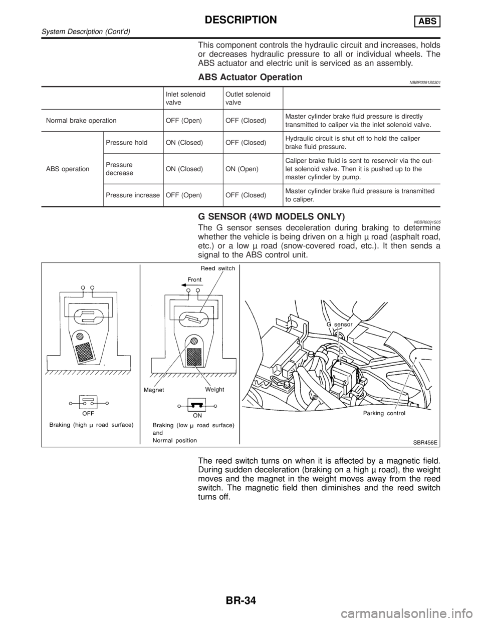
This component controls the hydraulic circuit and increases, holds
or decreases hydraulic pressure to all or individual wheels. The
ABS actuator and electric unit is serviced as an assembly.
ABS Actuator OperationNBBR0091S0301
Inlet solenoid
valveOutlet solenoid
valve
Normal brake operation OFF (Open) OFF (Closed)Master cylinder brake fluid pressure is directly
transmitted to caliper via the inlet solenoid valve.
ABS operationPressure hold ON (Closed) OFF (Closed)Hydraulic circuit is shut off to hold the caliper
brake fluid pressure.
Pressure
decreaseON (Closed) ON (Open)Caliper brake fluid is sent to reservoir via the out-
let solenoid valve. Then it is pushed up to the
master cylinder by pump.
Pressure increase OFF (Open) OFF (Closed)Master cylinder brake fluid pressure is transmitted
to caliper.
G SENSOR (4WD MODELS ONLY)NBBR0091S05The G sensor senses deceleration during braking to determine
whether the vehicle is being driven on a high road (asphalt road,
etc.) or a low road (snow-covered road, etc.). It then sends a
signal to the ABS control unit.
SBR456E
The reed switch turns on when it is affected by a magnetic field.
During sudden deceleration (braking on a high road), the weight
moves and the magnet in the weight moves away from the reed
switch. The magnetic field then diminishes and the reed switch
turns off.
DESCRIPTIONABS
System Description (Cont'd)
BR-34
Page 434 of 2395
![INFINITI QX4 2001 Factory Service Manual SELF-DIAGNOSTIC RESULTS MODENBBR0097S02
Diagnostic item Diagnostic item is detected when ... Reference Page
FR RH SENSOR*1
[OPEN]ICircuit for front right wheel sensor is open.
(An abnormally high inpu INFINITI QX4 2001 Factory Service Manual SELF-DIAGNOSTIC RESULTS MODENBBR0097S02
Diagnostic item Diagnostic item is detected when ... Reference Page
FR RH SENSOR*1
[OPEN]ICircuit for front right wheel sensor is open.
(An abnormally high inpu](/img/42/57027/w960_57027-433.png)
SELF-DIAGNOSTIC RESULTS MODENBBR0097S02
Diagnostic item Diagnostic item is detected when ... Reference Page
FR RH SENSOR*1
[OPEN]ICircuit for front right wheel sensor is open.
(An abnormally high input voltage is entered.)BR-56
FR LH SENSOR*1
[OPEN]ICircuit for front left wheel sensor is open.
(An abnormally high input voltage is entered.)BR-56
RR RH SENSOR*1
[OPEN]ICircuit for rear right sensor is open.
(An abnormally high input voltage is entered.)BR-56
RR LH SENSOR*1
[OPEN]ICircuit for rear left sensor is open.
(An abnormally high input voltage is entered.)BR-56
FR RH SENSOR*1
[SHORT]ICircuit for front right wheel sensor is shorted.
(An abnormally low input voltage is entered.)BR-56
FR LH SENSOR*1
[SHORT]ICircuit for front left wheel sensor is shorted.
(An abnormally low input voltage is entered.)BR-56
RR RH SENSOR*1
[SHORT]ICircuit for rear right sensor is shorted.
(An abnormally low input voltage is entered.)BR-56
RR LH SENSOR*1
[SHORT]ICircuit for rear left sensor is shorted.
(An abnormally low input voltage is entered.)BR-56
ABS SENSOR*1
[ABNORMAL SIGNAL]ITeeth damage on sensor rotor or improper installation of wheel sensor.
(Abnormal wheel sensor signal is entered.)BR-56
FR RH IN ABS SOL
[OPEN, SHORT]ICircuit for front right inlet solenoid valve is open.
(An abnormally low output voltage is entered.)BR-59
FR LH IN ABS SOL
[OPEN, SHORT]ICircuit for front left inlet solenoid valve is open.
(An abnormally low output voltage is entered.)BR-59
FR RH OUT ABS SOL
[OPEN, SHORT]ICircuit for front right outlet solenoid valve is open.
(An abnormally low output voltage is entered.)BR-59
FR LH OUT ABS SOL
[OPEN, SHORT]ICircuit for front left outlet solenoid valve is open.
(An abnormally low output voltage is entered.)BR-59
RR IN ABS SOL
[OPEN, SHORT]ICircuit for rear inlet solenoid valve is shorted.
(An abnormally high output voltage is entered.)BR-59
RR OUT ABS SOL
[OPEN, SHORT]ICircuit for rear out solenoid valve is shorted.
(An abnormally high output voltage is entered.)BR-59
ABS ACTUATOR RELAY
[ABNORMAL]IActuator solenoid valve relay is ON, even if control unit sends off signal.
IActuator solenoid valve relay is OFF, even if control unit sends on signal.BR-59
ABS MOTOR RELAY
[ABNORMAL]ICircuit for ABS motor relay is open or shorted.
ICircuit for actuator motor is open or shorted.
IActuator motor relay is stuck.BR-61
BATTERY VOLT
[VB-LOW]IPower source voltage supplied to ABS control unit is abnormally low.
BR-63
CONTROL UNITIFunction of calculation in ABS control unit has failed. BR-68
G SENSOR*2
[ABNORMAL]IG sensor circuit is open or shorted.
BR-65
*1: If one or more wheels spin on a rough or slippery road for 40 seconds or more, the ABS warning lamp will illuminate. This does not
indicate a malfunction. Only in the case of the short-circuit (Code Nos. 26, 22, 32 and 36), after repair the ABS warning lamp also illu-
minates when the ignition switch is turned ON. In this case, drive the vehicle at speeds greater than 30 km/h (19 MPH) for approxi-
mately 1 minute as specified in ªSELF-DIAGNOSIS PROCEDUREº, BR-41. Check to ensure that the ABS warning lamp goes out while
the vehicle is being driven.
*2: 4WD models onlyGI
MA
EM
LC
EC
FE
AT
TF
PD
AX
SU
ST
RS
BT
HA
SC
EL
IDX
ON BOARD DIAGNOSTIC SYSTEM DESCRIPTIONABS
CONSULT-II Inspection Procedure (Cont'd)
BR-45
Page 443 of 2395

Malfunction Code/Symptom ChartNBBR0101
Code No. (No. of warning lamp flashes) Malfunctioning part Reference Page
12 Self-diagnosis could not detect any malfunctions. Ð
17*4 G sensor and circuit BR-65
18*1 Sensor rotor BR-56
21*1 Front right sensor (open-circuit) BR-56
22*1 Front right sensor (short-circuit) BR-56
25*1 Front left sensor (open-circuit) BR-56
26*1 Front left sensor (short-circuit) BR-56
31*1 Rear right sensor (open-circuit) BR-56
32*1 Rear right sensor (short-circuit) BR-56
35*1 Rear left sensor (open-circuit) BR-56
36*1 Rear left sensor (short-circuit) BR-56
41 Actuator front right outlet solenoid valve BR-59
42 Actuator front right inlet solenoid valve BR-59
45 Actuator front left outlet solenoid valve BR-59
46 Actuator front left inlet solenoid valve BR-59
55 Actuator rear outlet solenoid valve BR-59
56 Actuator rear inlet solenoid valve BR-59
57*2 Power supply (Low voltage) BR-63
61*3 Actuator motor or motor relay BR-61
63 Solenoid valve relay BR-59
71 Control unit BR-68
Warning lamp stays on when ignition
switch is turned ON.Control unit power supply circuit
Warning lamp bulb circuit
Control unit or control unit connector
Solenoid valve relay stuck
Power supply for solenoid valve relay coilBR-74
ABS works frequently Ð BR-69
Unexpected pedal action Ð BR-69
Long stopping distance Ð BR-70
ABS does not work Ð BR-71
Pedal vibration and noise Ð BR-71
Warning lamp does not come on
when ignition switch is turned ON.Fuse, warning lamp bulb or warning lamp circuit
Control unitBR-72
Vehicle vibrates excessively when ABS is
operating.ABS control unit to TCM circuit BR-77
*1: If one or more wheels spin on a rough or slippery road for 40 seconds or more, the ABS warning lamp will illuminate. This does not
indicate a malfunction. Only in the case of the short-circuit (Code Nos. 26, 22, 32 and 36), after repair the ABS warning lamp also illu-
minates when the ignition switch is turned ON. In this case, drive the vehicle at speeds greater than 30 km/h (19 MPH) for approxi-
mately 1 minute as specified in ªSELF-DIAGNOSIS PROCEDUREº, BR-41. Check to ensure that the ABS warning lamp goes out while
the vehicle is being driven.
*2: The trouble code ª57º, which refers to a low power supply voltage, does not indicate that the ABS control unit is malfunctioning. Do
not replace the ABS control unit with a new one.
TROUBLE DIAGNOSIS Ð GENERAL DESCRIPTIONABS
Malfunction Code/Symptom Chart
BR-54
Page 579 of 2395

IAir intake system
(Oil filler cap, oil level gauge, etc.)
IFuel pressure
IEngine compression
IThrottle valve
IEvaporative emission system
2) On air conditioner equipped models, checks should be carried out while the air conditioner is ªOFFº.
3) On automatic transmission equipped models, when checking idle rpm, ignition timing and mixture ratio,
checks should be carried out while shift lever is in ªNº position.
4) When measuring ªCOº percentage, insert probe more than 40 cm (15.7 in) into tail pipe.
5) Turn off headlamps, heater blower, rear defogger.
6) Keep front wheels pointed straight ahead.
7) Make the check after the cooling fan has stopped.
BASIC SERVICE PROCEDURE
Idle Speed/Ignition Timing/Idle Mixture Ratio Adjustment (Cont'd)
EC-44
Page 658 of 2395

MONITOR ITEM CONDITION SPECIFICATION
VHCL SPEED SEITurn drive wheels and compare speedometer indication with the CON-
SULT-II valueAlmost the same speed as
the CONSULT-II value
BATTERY VOLTIIgnition switch: ON (Engine stopped) 11 - 14V
THRTL POS SENIEngine: After warming up, idle
the engineThrottle valve: fully closed 0.15 - 0.85V
IEngine: After warming up
IIgnition switch: ON
(Engine stopped)Throttle valve: fully opened 3.5 - 4.7V
START SIGNALIIgnition switch: ON,START,ON OFF,ON,OFF
CLSD THL POS
CLSD THL/P SWIEngine: After warming up, idle
the engineThrottle valve: Idle position ON
Throttle valve: Slightly open OFF
AIR COND SIGIEngine: After warming up, idle
the engineAir conditioner switch: ªOFFº OFF
Air conditioner switch: ªONº
(Compressor operates.)ON
P/N POSI SWIIgnition switch: ONShift lever: ªPº or ªNº ON
Except above OFF
PW/ST SIGNALIEngine: After warming up, idle
the engineSteering wheel in neutral position
(forward direction)OFF
The steering wheel is turned ON
IGNITION SWIIgnition switch: ON,OFF,ON ON,OFF,ON
INJ PULSE-B2
INJ PULSE-B1IEngine: After warming up
IAir conditioner switch: ªOFFº
IShift lever: ªNº
INo-loadIdle 2.4 - 3.2 msec
2,000 rpm 1.9 - 2.8 msec
B/FUEL SCHDLIEngine: After warming up
IAir conditioner switch: ªOFFº
IShift lever: ªNº
INo-loadIdle 2.0 - 3.2 msec
2,000 rpm 1.4 - 2.6 msec
IGN TIMINGIEngine: After warming up
IAir conditioner switch: ªOFFº
IShift lever: ªNº
INo-loadIdle 15ɱ5É BTDC
2,000 rpm More than 25É BTDC
IACV-AAC/VIEngine: After warming up
IAir conditioner switch: ªOFFº
IShift lever: ªNº
INo-loadIdle 2 - 10 step
2,000 rpm Ð
PURG VOL C/VIEngine: After warming up
IAir conditioner switch: ªOFFº
IShift lever: ªNº
INo-loadIdle 0 %
2,000 rpm Ð
A/F ALPHA-B2
A/F ALPHA-B1IEngine: After warming upMaintaining engine speed at 2,000
rpm54 - 155%
EVAP SYS PRESIIgnition switch: ON Approx. 3.4V
AIR COND RLYIAir conditioner switch: OFF,ON OFF,ON
FUEL PUMP RLYIIgnition switch is turned to ON (Operates for 5 seconds)
IEngine running and crankingON
Except as shown above OFF
GI
MA
EM
LC
FE
AT
TF
PD
AX
SU
BR
ST
RS
BT
HA
SC
EL
IDX
TROUBLE DIAGNOSIS Ð GENERAL DESCRIPTION
CONSULT-II Reference Value in Data Monitor Mode (Cont'd)
EC-123
Page 669 of 2395
![INFINITI QX4 2001 Factory Service Manual TERMI-
NAL
NO.WIRE
COLORITEM CONDITION DATA (DC Voltage)
85 YCrankshaft position
sensor (POS)[Engine is running]
IIdle speedApproximately 2.4V
SEF057V
[Engine is running]
IEngine speed is 2,000 rpm.Ap INFINITI QX4 2001 Factory Service Manual TERMI-
NAL
NO.WIRE
COLORITEM CONDITION DATA (DC Voltage)
85 YCrankshaft position
sensor (POS)[Engine is running]
IIdle speedApproximately 2.4V
SEF057V
[Engine is running]
IEngine speed is 2,000 rpm.Ap](/img/42/57027/w960_57027-668.png)
TERMI-
NAL
NO.WIRE
COLORITEM CONDITION DATA (DC Voltage)
85 YCrankshaft position
sensor (POS)[Engine is running]
IIdle speedApproximately 2.4V
SEF057V
[Engine is running]
IEngine speed is 2,000 rpm.Approximately 2.3V
SEF058V
86 W/L Vehicle speed sensor[Engine is running]
IJack up front wheels.
IIn 1st gear position
I10 km/h (6 MPH)Approximately 2.5VSEF583X
[Engine is running]
IJack up front wheels.
IIn 2nd gear position
I30 km/h (19 MPH)Approximately 2.0V
SEF584X
89 ORIntake valve timing
control position sen-
sors (LH)[Engine is running]
IWarm-up condition
IIdle speedApproximatley 0.5VSEF351Z
[Engine is running]
IWarm-up condition
IEngine speed is 2,000 rpm.Approximatley 0.5V
SEF352Z
TROUBLE DIAGNOSIS Ð GENERAL DESCRIPTION
ECM Terminals and Reference Value (Cont'd)
EC-134