brake rotor INFINITI QX4 2001 Factory Service Manual
[x] Cancel search | Manufacturer: INFINITI, Model Year: 2001, Model line: QX4, Model: INFINITI QX4 2001Pages: 2395, PDF Size: 43.2 MB
Page 365 of 2395

LOW & REVERSE BRAKENBAT0167S05
Code number4EX16 4EX17
Number of drive plates8
Number of driven plates8
Thickness of drive plate mm (in)Standard 1.90 - 2.05 (0.0748 - 0.0807) 1.52 - 1.67 (0.0598 - 0.0657)
Wear limit 1.40 (0.0551)
Clearance mm (in)Standard 0.8 - 1.1 (0.031 - 0.043)
Allowable limit 2.7 (0.106)
Thickness of retaining plateThickness mm (in) Part number*
7.6 (0.299)
7.8 (0.307)
8.0 (0.315)
8.2 (0.323)
8.4 (0.331)
8.6 (0.339)
8.8 (0.346)
9.0 (0.354)
9.2 (0.362)
9.4 (0.370)
9.6 (0.378)31667-41X07
31667-41X08
31667-41X00
31667-41X01
31667-41X02
31667-41X03
31667-41X04
31667-41X05
31667-41X06
31667-41X09
31667-41X10
BRAKE BANDNBAT0167S06
Anchor end bolt nut tightening torque 40 - 51 N´m (4.1 - 5.2 kg-m, 30 - 38 ft-lb)
Anchor end bolt tightening torque4 - 6 N´m (0.4 - 0.6 kg-m, 35 - 52 in-lb)
Number of returning revolution for anchor end bolt 2.5
Oil Pump and Low One-way ClutchNBAT0168Unit: mm (in)
Oil pump clearanceCam ring Ð oil pump housing Standard 0.01 - 0.024 (0.0004 - 0.0009)
Rotor, vanes and control piston Ð oil
pump housingStandard 0.03 - 0.044 (0.0012 - 0.0017)
Seal ring clearanceStandard 0.10 - 0.25 (0.0039 - 0.0098)
Allowable limit 0.25 (0.0098)
Total End PlayNBAT0169
Total end play ªT1º 0.25 - 0.55 mm (0.0098 - 0.0217 in)
Thickness of oil pump cover bearing raceThickness mm (in) Part number*
0.8 (0.031)
1.0 (0.039)
1.2 (0.047)
1.4 (0.055)
1.6 (0.063)
1.8 (0.071)
2.0 (0.079)31435-41X01
31435-41X02
31435-41X03
31435-41X04
31435-41X05
31435-41X06
31435-41X07
SERVICE DATA AND SPECIFICATIONS (SDS)
Clutches and Brakes (Cont'd)
AT-360
Page 370 of 2395
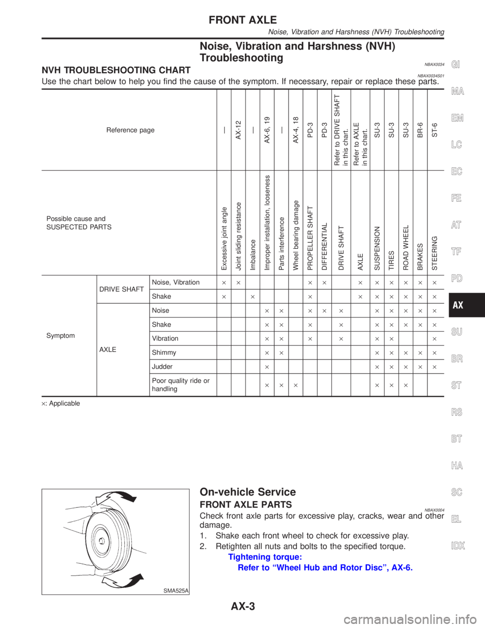
Noise, Vibration and Harshness (NVH)
Troubleshooting
NBAX0034NVH TROUBLESHOOTING CHARTNBAX0034S01Use the chart below to help you find the cause of the symptom. If necessary, repair or replace these parts.
Reference pageÐ
AX-12
Ð
AX-6, 19
Ð
AX-4, 18
PD-3
PD-3
Refer to DRIVE SHAFT
in this chart.
Refer to AXLE
in this chart.
SU-3
SU-3
SU-3
BR-6
ST-6
Possible cause and
SUSPECTED PARTS
Excessive joint angle
Joint sliding resistance
Imbalance
Improper installation, looseness
Parts interference
Wheel bearing damage
PROPELLER SHAFT
DIFFERENTIAL
DRIVE SHAFT
AXLE
SUSPENSION
TIRES
ROAD WHEEL
BRAKES
STEERING
SymptomDRIVE SHAFTNoise, Vibration´´ ´´ ´ ´´´´´
Shake´ ´ ´ ´ ´´´´´
AXLENoise´´ ´´ ´ ´´´´´
Shake´´ ´ ´ ´´´´´
Vibration´´ ´ ´ ´´ ´
Shimmy´´ ´´´´´
Judder´ ´´´´´
Poor quality ride or
handling´´´ ´´´
´: Applicable
SMA525A
On-vehicle Service
FRONT AXLE PARTSNBAX0004Check front axle parts for excessive play, cracks, wear and other
damage.
1. Shake each front wheel to check for excessive play.
2. Retighten all nuts and bolts to the specified torque.
Tightening torque:
Refer to ªWheel Hub and Rotor Discº, AX-6.
GI
MA
EM
LC
EC
FE
AT
TF
PD
SU
BR
ST
RS
BT
HA
SC
EL
IDX
FRONT AXLE
Noise, Vibration and Harshness (NVH) Troubleshooting
AX-3
Page 373 of 2395
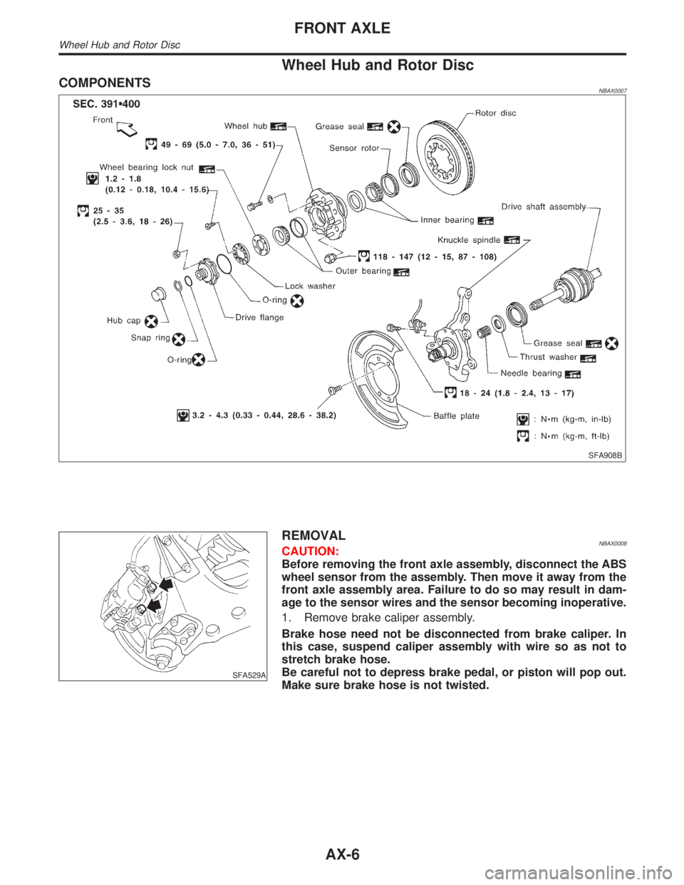
Wheel Hub and Rotor Disc
COMPONENTSNBAX0007
SFA908B
SFA529A
REMOVALNBAX0008CAUTION:
Before removing the front axle assembly, disconnect the ABS
wheel sensor from the assembly. Then move it away from the
front axle assembly area. Failure to do so may result in dam-
age to the sensor wires and the sensor becoming inoperative.
1. Remove brake caliper assembly.
Brake hose need not be disconnected from brake caliper. In
this case, suspend caliper assembly with wire so as not to
stretch brake hose.
Be careful not to depress brake pedal, or piston will pop out.
Make sure brake hose is not twisted.
FRONT AXLE
Wheel Hub and Rotor Disc
AX-6
Page 390 of 2395

BRAKE SYSTEM
SECTION
BR
CONTENTS
PRECAUTIONS...............................................................3
Supplemental Restraint System (SRS)²AIR
BAG²and²SEAT BELT PRE-TENSIONER²...............3
Precautions for Brake System .....................................3
Wiring Diagrams and Trouble Diagnoses....................4
PREPARATION...............................................................5
Special Service Tools ..................................................5
Commercial Service Tools ...........................................5
NOISE, VIBRATION AND HARSHNESS (NVH)
TROUBLESHOOTING.....................................................6
NVH Troubleshooting Chart.........................................6
ON-VEHICLE SERVICE..................................................7
Checking Brake Fluid Level.........................................7
Checking Brake Line ...................................................7
Changing Brake Fluid ..................................................7
Bleeding Brake System ...............................................8
BRAKE HYDRAULIC LINE.............................................9
Hydraulic Circuit...........................................................9
Removal .....................................................................10
Inspection...................................................................10
Installation ..................................................................10
PROPORTIONING VALVE (2WD)................................ 11
Inspection................................................................... 11
Removal and Installation (Built-in type)..................... 11
LOAD SENSING VALVE (4WD)...................................12
Inspection...................................................................12
Removal and Installation ...........................................12
BRAKE PEDAL AND BRACKET..................................14
Removal and Installation ...........................................14
Inspection...................................................................14
Adjustment .................................................................14
MASTER CYLINDER.....................................................16
Removal .....................................................................16
Disassembly...............................................................16
Inspection...................................................................17
Assembly ...................................................................17
Installation ..................................................................18
BRAKE BOOSTER........................................................19
On-vehicle Service.....................................................19OPERATING CHECK...............................................19
AIRTIGHT CHECK...................................................19
Removal .....................................................................19
Inspection...................................................................19
OUTPUT ROD LENGTH CHECK..............................19
Installation ..................................................................20
VACUUM PIPING...........................................................21
Vacuum Hose ............................................................21
Removal and Installation ...........................................21
Inspection...................................................................21
HOSES AND CONNECTORS...................................21
CHECK VALVE........................................................21
FRONT DISC BRAKE...................................................22
Components...............................................................22
Pad Replacement ......................................................22
Removal .....................................................................23
Disassembly...............................................................24
Inspection...................................................................24
CALIPER.................................................................24
ROTOR...................................................................24
Assembly ...................................................................25
Installation ..................................................................25
Brake Burnishing Procedure......................................25
REAR DRUM BRAKE...................................................26
Components...............................................................26
Removal .....................................................................26
Inspection...................................................................27
WHEEL CYLINDER..................................................27
Wheel Cylinder Overhaul...........................................28
Inspection...................................................................28
DRUM.....................................................................28
LINING....................................................................28
Installation ..................................................................28
PARKING BRAKE CONTROL......................................30
Components...............................................................30
Removal and Installation ...........................................30
Inspection...................................................................30
Adjustment .................................................................31
GI
MA
EM
LC
EC
FE
AT
TF
PD
AX
SU
ST
RS
BT
HA
SC
EL
IDX
Page 391 of 2395
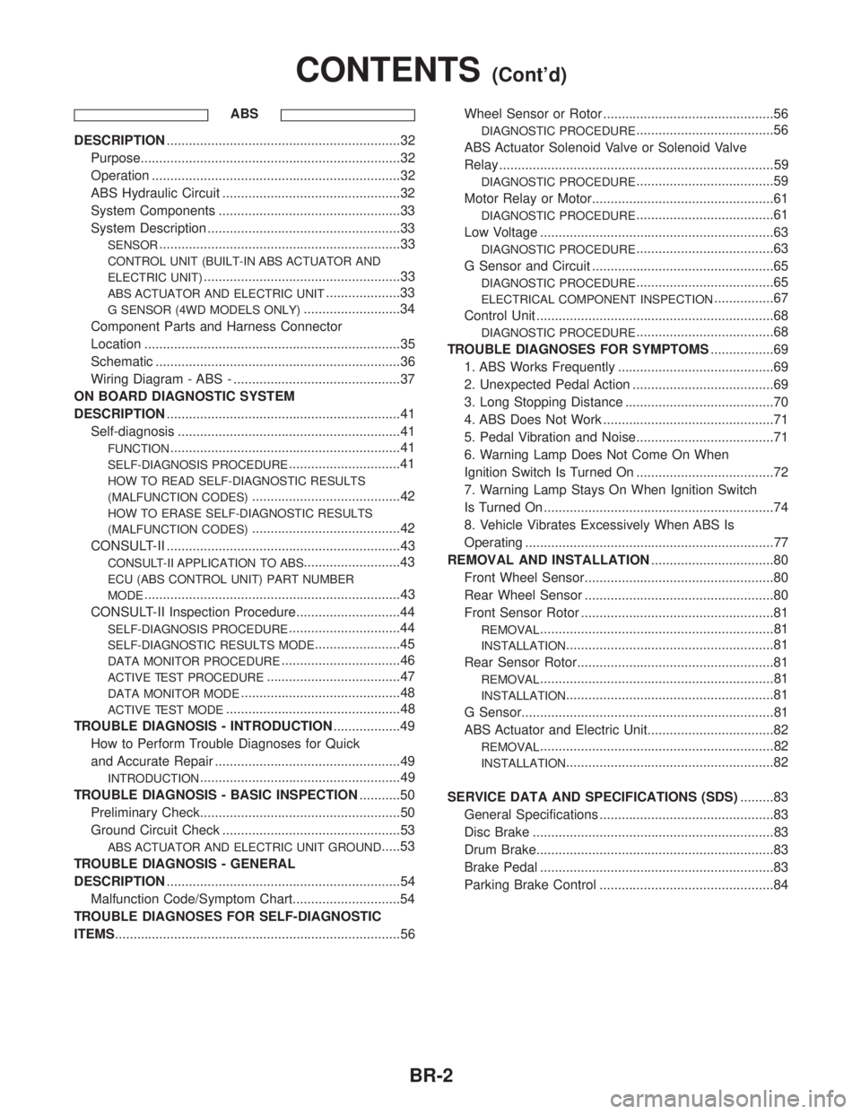
ABS
DESCRIPTION...............................................................32
Purpose......................................................................32
Operation ...................................................................32
ABS Hydraulic Circuit ................................................32
System Components .................................................33
System Description ....................................................33
SENSOR.................................................................33
CONTROL UNIT (BUILT-IN ABS ACTUATOR AND
ELECTRIC UNIT)
.....................................................33
ABS ACTUATOR AND ELECTRIC UNIT....................33
G SENSOR (4WD MODELS ONLY)..........................34
Component Parts and Harness Connector
Location .....................................................................35
Schematic ..................................................................36
Wiring Diagram - ABS - .............................................37
ON BOARD DIAGNOSTIC SYSTEM
DESCRIPTION...............................................................41
Self-diagnosis ............................................................41
FUNCTION..............................................................41
SELF-DIAGNOSIS PROCEDURE..............................41
HOW TO READ SELF-DIAGNOSTIC RESULTS
(MALFUNCTION CODES)
........................................42
HOW TO ERASE SELF-DIAGNOSTIC RESULTS
(MALFUNCTION CODES)
........................................42
CONSULT-II ...............................................................43
CONSULT-II APPLICATION TO ABS..........................43
ECU (ABS CONTROL UNIT) PART NUMBER
MODE
.....................................................................43
CONSULT-II Inspection Procedure............................44
SELF-DIAGNOSIS PROCEDURE..............................44
SELF-DIAGNOSTIC RESULTS MODE.......................45
DATA MONITOR PROCEDURE................................46
ACTIVE TEST PROCEDURE....................................47
DATA MONITOR MODE...........................................48
ACTIVE TEST MODE...............................................48
TROUBLE DIAGNOSIS - INTRODUCTION..................49
How to Perform Trouble Diagnoses for Quick
and Accurate Repair ..................................................49
INTRODUCTION......................................................49
TROUBLE DIAGNOSIS - BASIC INSPECTION...........50
Preliminary Check......................................................50
Ground Circuit Check ................................................53
ABS ACTUATOR AND ELECTRIC UNIT GROUND.....53
TROUBLE DIAGNOSIS - GENERAL
DESCRIPTION...............................................................54
Malfunction Code/Symptom Chart.............................54
TROUBLE DIAGNOSES FOR SELF-DIAGNOSTIC
ITEMS.............................................................................56Wheel Sensor or Rotor ..............................................56
DIAGNOSTIC PROCEDURE.....................................56
ABS Actuator Solenoid Valve or Solenoid Valve
Relay ..........................................................................59
DIAGNOSTIC PROCEDURE.....................................59
Motor Relay or Motor.................................................61
DIAGNOSTIC PROCEDURE.....................................61
Low Voltage ...............................................................63
DIAGNOSTIC PROCEDURE.....................................63
G Sensor and Circuit .................................................65
DIAGNOSTIC PROCEDURE.....................................65
ELECTRICAL COMPONENT INSPECTION................67
Control Unit ................................................................68
DIAGNOSTIC PROCEDURE.....................................68
TROUBLE DIAGNOSES FOR SYMPTOMS.................69
1. ABS Works Frequently ..........................................69
2. Unexpected Pedal Action ......................................69
3. Long Stopping Distance ........................................70
4. ABS Does Not Work ..............................................71
5. Pedal Vibration and Noise.....................................71
6. Warning Lamp Does Not Come On When
Ignition Switch Is Turned On .....................................72
7. Warning Lamp Stays On When Ignition Switch
Is Turned On ..............................................................74
8. Vehicle Vibrates Excessively When ABS Is
Operating ...................................................................77
REMOVAL AND INSTALLATION.................................80
Front Wheel Sensor...................................................80
Rear Wheel Sensor ...................................................80
Front Sensor Rotor ....................................................81
REMOVAL...............................................................81
INSTALLATION........................................................81
Rear Sensor Rotor.....................................................81
REMOVAL...............................................................81
INSTALLATION........................................................81
G Sensor....................................................................81
ABS Actuator and Electric Unit..................................82
REMOVAL...............................................................82
INSTALLATION........................................................82
SERVICE DATA AND SPECIFICATIONS (SDS).........83
General Specifications ...............................................83
Disc Brake .................................................................83
Drum Brake................................................................83
Brake Pedal ...............................................................83
Parking Brake Control ...............................................84
CONTENTS(Cont'd)
BR-2
Page 394 of 2395
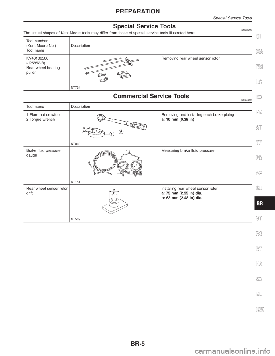
Special Service ToolsNBBR0004The actual shapes of Kent-Moore tools may differ from those of special service tools illustrated here.
Tool number
(Kent-Moore No.)
Tool nameDescription
KV40106500
(J25852-B)
Rear wheel bearing
puller
NT724
Removing rear wheel sensor rotor
Commercial Service ToolsNBBR0005
Tool name Description
1 Flare nut crowfoot
2 Torque wrench
NT360
Removing and installing each brake piping
a: 10 mm (0.39 in)
Brake fluid pressure
gauge
NT151
Measuring brake fluid pressure
Rear wheel sensor rotor
drift
NT509
Installing rear wheel sensor rotor
a: 75 mm (2.95 in) dia.
b: 63 mm (2.48 in) dia.
GI
MA
EM
LC
EC
FE
AT
TF
PD
AX
SU
ST
RS
BT
HA
SC
EL
IDX
PREPARATION
Special Service Tools
BR-5
Page 395 of 2395

NBBR0085
NVH Troubleshooting ChartNBBR0085S01Use the chart below to help you find the cause of the symptom. If necessary, repair or replace these parts.
Reference page
BR-22, 28
BR-22, 28
BR-26
BR-22
Ð
Ð
BR-24, 28
Ð
Ð
Ð
BR-25
BR-28
PD-3
PD-3
AX-3
AX-3
SU-3
SU-3
SU-3
ST-6
Possible cause and
SUSPECTED PARTS
Linings or pads - damaged
Linings or pads - uneven wear
Return spring damaged
Shims damaged
Rotor or drum imbalance
Rotor or drum damage
Rotor or drum runout
Rotor or drum deformation
Rotor or drum deflection
Rotor or drum rust
Rotor thickness variation
Drum out of round
PROPELLER SHAFT
DIFFERENTIAL
DRIVE SHAFT
AXLE
SUSPENSION
TIRES
ROAD WHEEL
STEERING
Symptom BRAKENoise´´´´ ´´´´´´´´
Shake´ ´ ´´´´´´
Shimmy, Judder´´´´´´´´ ´´´´´
´: Applicable
NOISE, VIBRATION AND HARSHNESS (NVH) TROUBLESHOOTING
NVH Troubleshooting Chart
BR-6
Page 411 of 2395
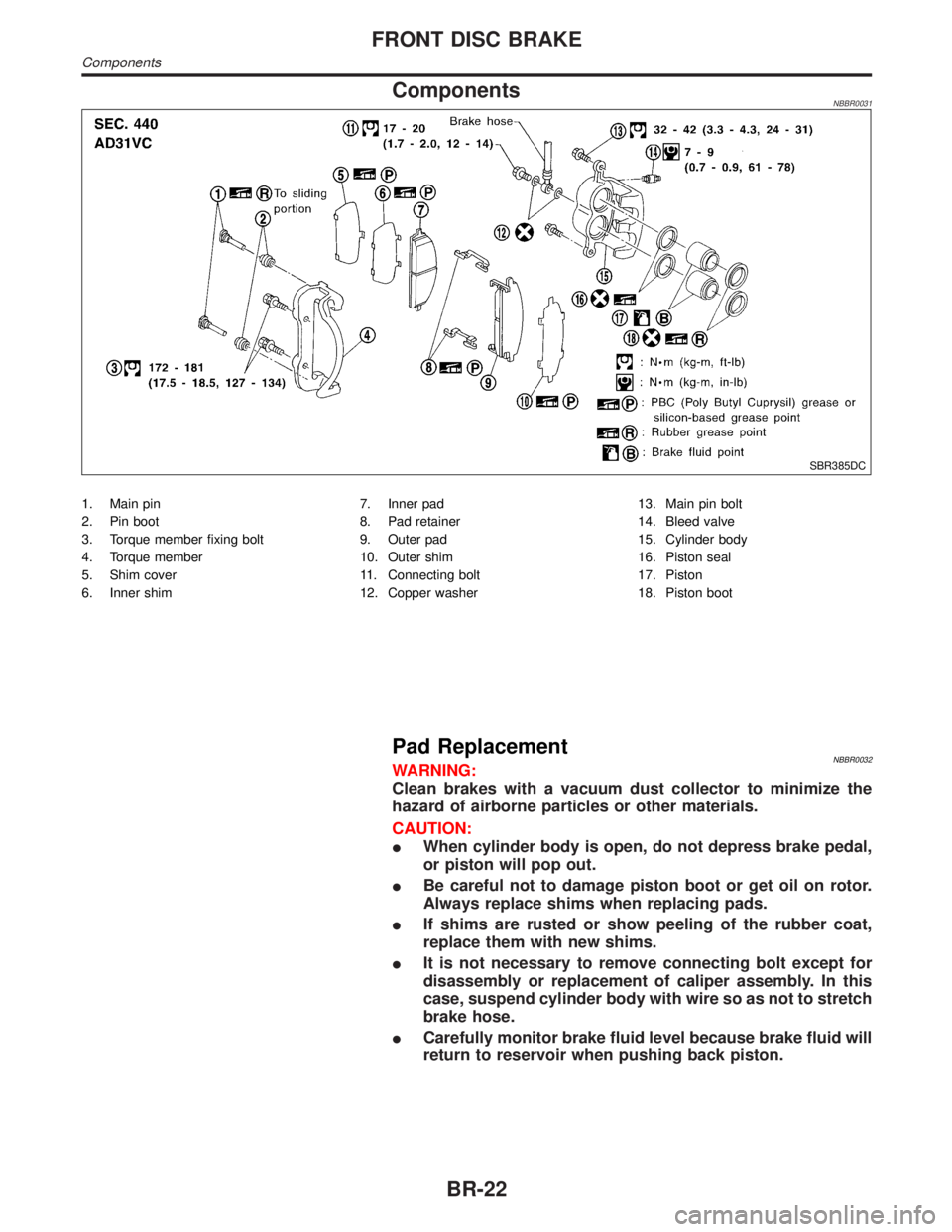
ComponentsNBBR0031
SBR385DC
1. Main pin
2. Pin boot
3. Torque member fixing bolt
4. Torque member
5. Shim cover
6. Inner shim7. Inner pad
8. Pad retainer
9. Outer pad
10. Outer shim
11. Connecting bolt
12. Copper washer13. Main pin bolt
14. Bleed valve
15. Cylinder body
16. Piston seal
17. Piston
18. Piston boot
Pad ReplacementNBBR0032WARNING:
Clean brakes with a vacuum dust collector to minimize the
hazard of airborne particles or other materials.
CAUTION:
IWhen cylinder body is open, do not depress brake pedal,
or piston will pop out.
IBe careful not to damage piston boot or get oil on rotor.
Always replace shims when replacing pads.
IIf shims are rusted or show peeling of the rubber coat,
replace them with new shims.
IIt is not necessary to remove connecting bolt except for
disassembly or replacement of caliper assembly. In this
case, suspend cylinder body with wire so as not to stretch
brake hose.
ICarefully monitor brake fluid level because brake fluid will
return to reservoir when pushing back piston.
FRONT DISC BRAKE
Components
BR-22
Page 413 of 2395
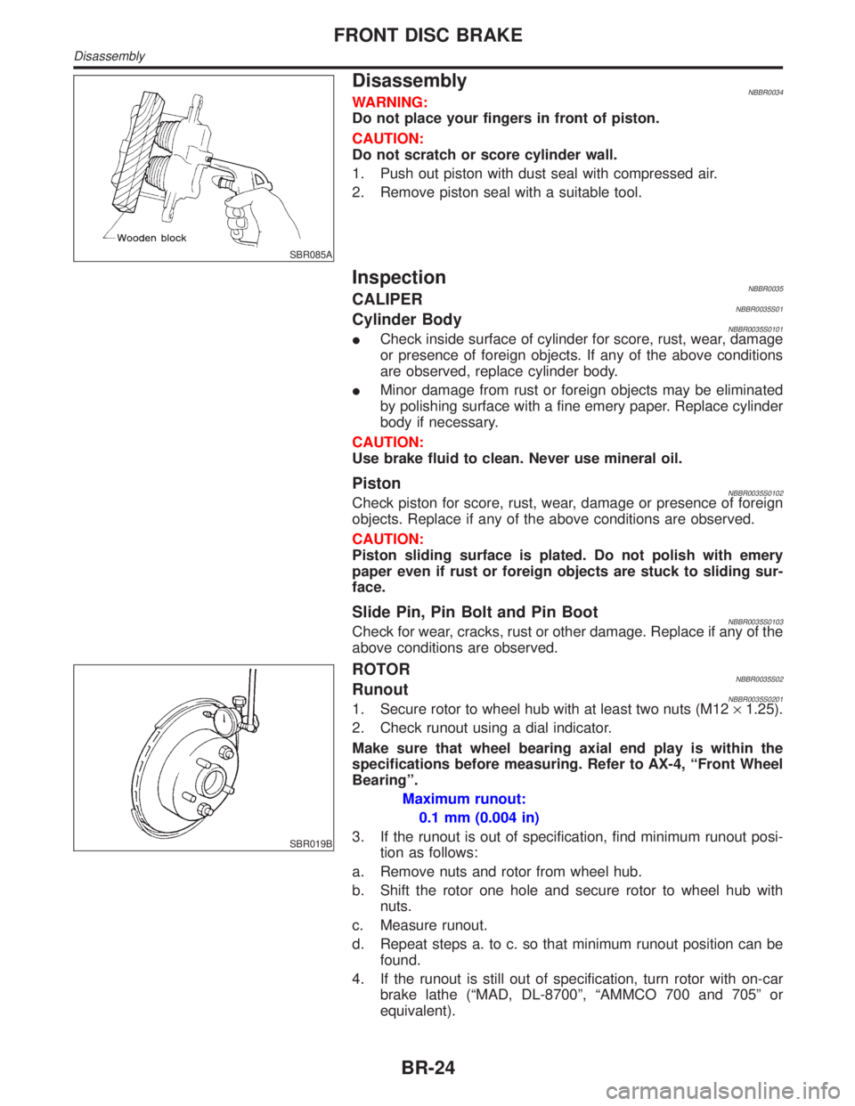
SBR085A
DisassemblyNBBR0034WARNING:
Do not place your fingers in front of piston.
CAUTION:
Do not scratch or score cylinder wall.
1. Push out piston with dust seal with compressed air.
2. Remove piston seal with a suitable tool.
InspectionNBBR0035CALIPERNBBR0035S01Cylinder BodyNBBR0035S0101ICheck inside surface of cylinder for score, rust, wear, damage
or presence of foreign objects. If any of the above conditions
are observed, replace cylinder body.
IMinor damage from rust or foreign objects may be eliminated
by polishing surface with a fine emery paper. Replace cylinder
body if necessary.
CAUTION:
Use brake fluid to clean. Never use mineral oil.
PistonNBBR0035S0102Check piston for score, rust, wear, damage or presence of foreign
objects. Replace if any of the above conditions are observed.
CAUTION:
Piston sliding surface is plated. Do not polish with emery
paper even if rust or foreign objects are stuck to sliding sur-
face.
Slide Pin, Pin Bolt and Pin BootNBBR0035S0103Check for wear, cracks, rust or other damage. Replace if any of the
above conditions are observed.
SBR019B
ROTORNBBR0035S02RunoutNBBR0035S02011. Secure rotor to wheel hub with at least two nuts (M12´1.25).
2. Check runout using a dial indicator.
Make sure that wheel bearing axial end play is within the
specifications before measuring. Refer to AX-4, ªFront Wheel
Bearingº.
Maximum runout:
0.1 mm (0.004 in)
3. If the runout is out of specification, find minimum runout posi-
tion as follows:
a. Remove nuts and rotor from wheel hub.
b. Shift the rotor one hole and secure rotor to wheel hub with
nuts.
c. Measure runout.
d. Repeat steps a. to c. so that minimum runout position can be
found.
4. If the runout is still out of specification, turn rotor with on-car
brake lathe (ªMAD, DL-8700º, ªAMMCO 700 and 705º or
equivalent).
FRONT DISC BRAKE
Disassembly
BR-24
Page 414 of 2395

SBR020B
ThicknessNBBR0035S0202Thickness variation (At least 8 positions):
Maximum 0.015 mm (0.0006 in)
If thickness variation exceeds the specification, turn rotor with on-
car brake lathe.
Rotor repair limit:
26.0 mm (1.024 in)
SBR574
AssemblyNBBR00361. Insert piston seal into groove on cylinder body.
2. With piston boot fitted to piston, insert piston boot into groove
on cylinder body and install piston.
3. Properly secure piston boot
SBR387D
InstallationNBBR0037CAUTION:
IRefill with new brake fluid ªDOT 3º.
INever reuse drained brake fluid.
1. Install caliper assembly.
2. Install brake hose to caliper securely.
3. Install all parts and secure all bolts.
4. Bleed air. Refer to ªBleeding Brake Systemº, BR-8.
Brake Burnishing ProcedureNBBR0086When experiencing soft brake pedal feel at very low mileage, or
after replacing the rotor, burnish the brake pad contact surfaces
according to the following procedures.
CAUTION:
Only perform this procedure under safe road and traffic con-
ditions. Use extreme caution.
1. Drive the vehicle on a straight smooth road at 50 km/h (31
MPH).
2. Use medium brake pedal/foot effort to bring the vehicle to a
complete stop from 50 km/h (31 MPH). Adjust brake pedal/foot
pressure such that vehicle stopping time equals 3 to 5 sec-
onds.
3. To cool the brake system, drive the vehicle at 50 km/h (31
MPH) for 1 minute without stopping.
4. Repeat steps 1 to 3 10 times or more to complete the burnish-
ing procedure.
GI
MA
EM
LC
EC
FE
AT
TF
PD
AX
SU
ST
RS
BT
HA
SC
EL
IDX
FRONT DISC BRAKE
Inspection (Cont'd)
BR-25