width INFINITI QX4 2001 Factory User Guide
[x] Cancel search | Manufacturer: INFINITI, Model Year: 2001, Model line: QX4, Model: INFINITI QX4 2001Pages: 2395, PDF Size: 43.2 MB
Page 1688 of 2395

SEM934C
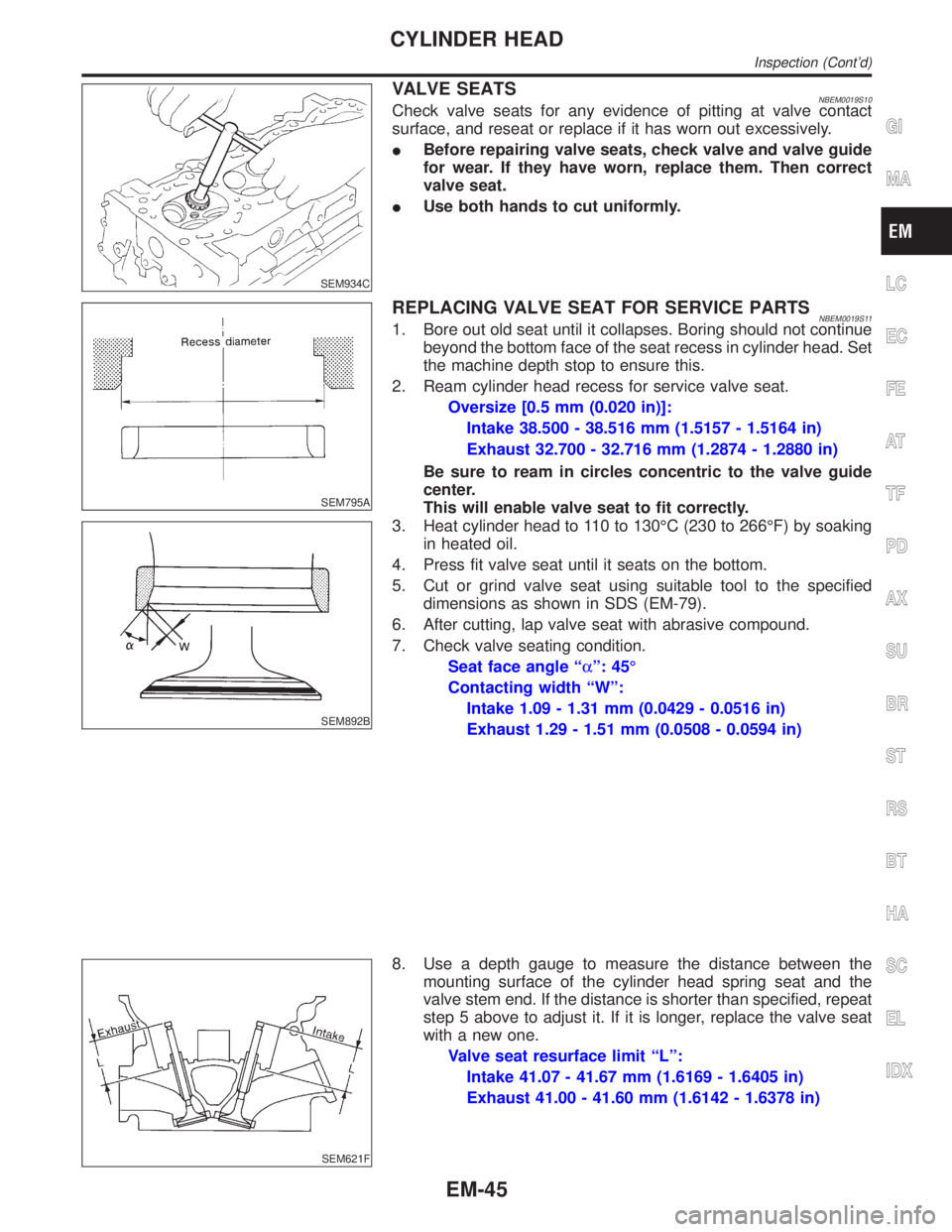
VALVE SEATSNBEM0019S10Check valve seats for any evidence of pitting at valve contact
surface, and reseat or replace if it has worn out excessively.
IBefore repairing valve seats, check valve and valve guide
for wear. If they have worn, replace them. Then correct
valve seat.
IUse both hands to cut uniformly.
SEM795A
REPLACING VALVE SEAT FOR SERVICE PARTSNBEM0019S111. Bore out old seat until it collapses. Boring should not continue
beyond the bottom face of the seat recess in cylinder head. Set
the machine depth stop to ensure this.
2. Ream cylinder head recess for service valve seat.
Oversize [0.5 mm (0.020 in)]:
Intake 38.500 - 38.516 mm (1.5157 - 1.5164 in)
Exhaust 32.700 - 32.716 mm (1.2874 - 1.2880 in)
Be sure to ream in circles concentric to the valve guide
center.
This will enable valve seat to fit correctly.
SEM892B
3. Heat cylinder head to 110 to 130ÉC (230 to 266ÉF) by soaking
in heated oil.
4. Press fit valve seat until it seats on the bottom.
5. Cut or grind valve seat using suitable tool to the specified
dimensions as shown in SDS (EM-79).
6. After cutting, lap valve seat with abrasive compound.
7. Check valve seating condition.
Seat face angle ªaº: 45É
Contacting width ªWº:
Intake 1.09 - 1.31 mm (0.0429 - 0.0516 in)
Exhaust 1.29 - 1.51 mm (0.0508 - 0.0594 in)
SEM621F
8. Use a depth gauge to measure the distance between the
mounting surface of the cylinder head spring seat and the
valve stem end. If the distance is shorter than specified, repeat
step 5 above to adjust it. If it is longer, replace the valve seat
with a new one.
Valve seat resurface limit ªLº:
Intake 41.07 - 41.67 mm (1.6169 - 1.6405 in)
Exhaust 41.00 - 41.60 mm (1.6142 - 1.6378 in)
GI
MA
LC
EC
FE
AT
TF
PD
AX
SU
BR
ST
RS
BT
HA
SC
EL
IDX
CYLINDER HEAD
Inspection (Cont'd)
EM-45
Page 1728 of 2395

Available Main BearingNBEM0039
SEM175F
Grade number Thickness ªTº mm (in)Width ªWº
mm (in)Identification color
(UPR/LWR)Remarks
0 2.000 - 2.003 (0.0787 - 0.0789)
19.9 - 20.1
(0.783 - 0.791)Black
Grade is the same for
upper and lower bearings. 1 2.003 - 2.006 (0.0789 - 0.0790) Brown
2 2.006 - 2.009 (0.0790 - 0.0791) Green
3 2.009 - 2.012 (0.0791 - 0.0792) Yellow
4 2.012 - 2.015 (0.0792 - 0.0793) Blue
5 2.015 - 2.018 (0.0793 - 0.0794) Pink
6 2.018 - 2.021 (0.0794 - 0.0796) Purple
7 2.021 - 2.024 (0.0796 - 0.0797) White
01UPP 2.003 - 2.006 (0.0789 - 0.0790)
Brown/Black
Grade is different for upper
and lower bearings. LWR 2.000 - 2.003 (0.0787 - 0.0789)
12UPR 2.006 - 2.009 (0.0790 - 0.0791)
Green/Brown
LWR 2.003 - 2.006 (0.0789 - 0.0790)
23UPR 2.009 - 2.012 (0.0791 - 0.0792)
Yellow/Green
LWR 2.006 - 2.009 (0.0790 - 0.0791)
34UPR 2.012 - 2.015 (0.0792 - 0.0793)
Blue/Yellow
LWR 2.009 - 2.012 (0.0791 - 0.0792)
45UPR 2.015 - 2.018 (0.0793 - 0.0794)
Pink/Blue
LWR 2.012 - 2.015 (0.0792 - 0.0793)
56UPR 2.018 - 2.021 (0.0794 - 0.0796)
Purple/Pink
LWR 2.015 - 2.018 (0.0793 - 0.0794)
67UPR 2.021 - 2.024 (0.0796 - 0.0797)
White/Purple
LWR 2.018 - 2.021 (0.0794 - 0.0796)
UNDERSIZENBEM0039S01Unit: mm (in)
Thickness Main journal diameter ªDmº
0.25 (0.0098) 2.132 - 2.140 (0.0839 - 0.0843)Grind so that bearing clearance is the specified
value.
GI
MA
LC
EC
FE
AT
TF
PD
AX
SU
BR
ST
RS
BT
HA
SC
EL
IDX
SERVICE DATA AND SPECIFICATIONS (SDS)
Available Main Bearing
EM-85
Page 1788 of 2395

SGI136A
ENGINE SERIAL NUMBERNBGI0007S0203
MGI042A
AUTOMATIC TRANSMISSION NUMBERNBGI0007S0204
MGI043A
TRANSFER SERIAL NUMBERNBGI0007S0205
DimensionsNBGI0007S03Unit: mm (in)
Wagon
VQ35DE
Overall length 4,650 (183.1)
Overall width 1,840 (72.4)
Overall height1,730 (68.1)
1,795 (70.7)*
Front tread 1,540 (60.6)
Rear tread 1,545 (60.8)
Wheelbase 2,700 (106.3)
*: With luggage rack
MA
EM
LC
EC
FE
AT
TF
PD
AX
SU
BR
ST
RS
BT
HA
SC
EL
IDX
IDENTIFICATION INFORMATION
Identification Number (Cont'd)
GI-43
Page 1967 of 2395

S/VCSW - Wiring diagram ...........................EC-493
Swirl control valve control solenoid
valve .........................................................EC-458
Swirl control valve control vacuum
check switch .............................................EC-493
SWL/V - Wiring diagram ..............................EC-458
Symbols and abbreviations .............................GI-10
Symptom matrix chart...................................EC-118
System readiness test (SRT) code ................EC-61
T
2-4WD shift solenoid valve............................TF-111
Tachometer .....................................................EL-94
Tail lamp ..........................................................EL-61
TAIL/L - Wiring diagram ..................................EL-63
TCM circuit diagram ........................................AT-13
TCM inspection table ......................................AT-92
TFTS - Wiring diagram .................................EC-311
THEFT - Wiring diagram ...............................EL-300
Theft warning system....................................EL-294
Thermometer .................................................EL-110
Thermostat ......................................................LC-16
Three way catalyst function (Left bank) .......EC-347
Three way catalyst function (Right
bank) .........................................................EC-347
Three way catalyst precautions.........................GI-6
Throttle bodies ...............................................EM-12
Throttle position sensor (TPS) .....................EC-174
Throttle position sensor adjustment .............EC-101
Throttle position switch ...........EC-431, AT-184, 264
Tie-rod .............................................................ST-21
Tie-rod ball joints.............................................ST-21
Tightening torque of standard bolts.................GI-50
Timing chain ...................................................EM-20
Tire rotation ....................................................MA-24
Tire size ...........................................................GI-44
TLID - Wiring diagram ..................................EL-179
Tooth contact (front final drive 4WD) .............PD-29
Tooth contact diff. ...........................................PD-56
Torque converter installation .........................AT-278
Torque convertor clutch solenoid
valve ..................................................AT-152, 161
Tow truck towing ..............................................GI-47
Towing point.....................................................GI-49
TP/SW - Wiring diagram ..............................EC-434
TPS - Wiring diagram...................................EC-180
Transfer control unit inspection table..............TF-55
Transfer dropping resistor .............................TF-112
Transfer fluid replacement (Part time
4WD model) ...............................................MA-22
Transfer fluid temperature sensor .................TF-111
Transfer motor ...............................................TF-117
Transfer motor relay ......................................TF-113
Transfer serial number ....................................GI-43
TRANSMT - Wiring diagram .........................EL-325
Tread-FR&RR (Dimensions)............................GI-43
Trim .................................................................BT-28
Trouble diagnoses ...........................................GI-34
Trunk lid opener, electric...............................EL-178Turbine revolution sensor..............................AT-202
TURN - Wiring diagram ..................................EL-77
Turn signal lamp .............................................EL-75
Two trip detection logic ..................................EC-59
Two-pole lift .....................................................GI-47
U
Under body .....................................................BT-60
V
Vacuum cut valve ...........................................EC-32
Vacuum cut valve bypass valve.....EC-32, 585, 591
Vacuum hose (brake system).........................BR-21
Vacuum hose drawing (Engine control) .........EC-26
Valve clearance ..............................................EM-52
Valve guide.....................................................EM-43
Valve seat.......................................................EM-45
Valve spring....................................................EM-46
Vehicle identification number...........................GI-42
Vehicle recovery (freeing a stuck
vehicle) .........................................................GI-49
Vehicle speed sensor (VSS) ........................EC-417
VENT/V - Wiring diagram ............EC-376, 555, 576
Ventilation air filter ........................................HA-159
VIAS .............................................................EC-610
VIAS - Wiring diagram .................................EC-610
Viscosity number (SAE) .................................MA-12
VSS - Wiring diagram ..................................EC-420
W
Wait detection switch ....................................TF-112
WARN - Wiring diagram................................EL-115
Warning chime ..............................................EL-125
Warning lamps ..............................................EL-114
Washer, front .................................................EL-136
Washer, rear..................................................EL-141
Water pump ....................................................LC-12
Water temperature gauge ...............................EL-94
Weatherstrip - See Exterior ............................BT-35
Wheel balance ...............................................MA-24
Wheel bearing (front)........................................AX-4
Wheel bearing (rear) ......................................AX-18
Wheel hub (front)..............................................AX-6
Wheel sensors (ABS)...............................BR-56, 80
Wheel size .......................................................GI-44
Wheelarch height .............................................SU-5
Wheelbase (Dimensions) ................................GI-43
Wide open & closed throttle position
switch ........................................................EC-174
Width (Dimensions) .........................................GI-43
WINDOW - Wiring diagram ..........................EL-245
Window, door ..................................................BT-18
Window, rear side ...........................................BT-55
Window, side - See Rear side window ...........BT-55
ALPHABETICAL INDEX
IDX-8
Page 2159 of 2395

SEL406X
5. Locate the battery type and rating stamped or written on the
top case of the battery to be tested.
NOTE:
The battery type and rating will have either of the following.
CCA: Cold Cranking Amps (490 CCA, 550 CCA, etc.)
JIS: Japanese Industrial Standard.
Battery is stamped with a number such as:
80D26L: 80 (rank of output), D (physical size-depth), 26 (width
in cm). The last character L (post configuration) is not input into
the tester.
The tester requires the rating for the battery be entered exactly
as it is written or stamped on the battery. Do not attempt a CCA
conversion for JIS stamped batteries. JIS must be input
directly.
6. Using the arrow and ªENTERº keys alternately, select the bat-
tery type and rating.
NOTE:
The tester lists five choices; CCA, JIS, IEC, DIN, and EN. Only use
CCA or JIS.
SEL407X
7. Press ªENTERº to begin the test. Diagnosis results are dis-
played on the tester. Refer to ªDIAGNOSTIC RESULT ITEM
CHARTº SC-9.
SEL576X
8. Press ªENTERº, then test output code is displayed. Record the
test output code on the repair order.
9. Toggle back to the ªDIAGNOSTIC SCREENº for test results.
NOTE:
IIf necessary, the tester will ask the user to determine if the
battery has just been charged. Choose the appropriate selec-
tion by pressing the up or down arrow button and then press
the ªENTERº button to make the selection.
IWhen testing a battery installed in a vehicle that has recently
been driven, select ªBEFORE CHANGEº.
IIf the battery has just been slow charged due to a ªCHARGE
& RETESTº decision by the tester, and the tester asks the user
ªBEFORE CHARGE/AFTER CHARGEº, select ªAFTER
CHARGEº.
BATTERY
Trouble Diagnoses with Battery/Starting/Charging System Tester (Cont'd)
SC-8
Page 2270 of 2395
![INFINITI QX4 2001 Factory User Guide Item [Unit]Monitor item
Remarks
ECU input
signalsMain sig-
nalsItem menu
selection
Duty solenoid valve [%]
(Transfer 4WD solenoid valve)qH
2-4WD shift solenoid valve [ON-OFF]qH
Control signal outputs INFINITI QX4 2001 Factory User Guide Item [Unit]Monitor item
Remarks
ECU input
signalsMain sig-
nalsItem menu
selection
Duty solenoid valve [%]
(Transfer 4WD solenoid valve)qH
2-4WD shift solenoid valve [ON-OFF]qH
Control signal outputs](/img/42/57027/w960_57027-2269.png)
Item [Unit]Monitor item
Remarks
ECU input
signalsMain sig-
nalsItem menu
selection
Duty solenoid valve [%]
(Transfer 4WD solenoid valve)qH
2-4WD shift solenoid valve [ON-OFF]qH
Control signal outputs of transfer control unit Transfer motor relay [ON-OFF]qH
Shift activating 1 [ON-OFF]qH
Shift activating 2 [ON-OFF]qH
2-4WD shift solenoid valve monitor
[ON-OFF]H
Check signal (re-input signal) of transfer control
unit control signal output is displayed. If circuit
is shorted or open, ON/OFF state does not
change. Transfer motor relay monitor [ON-OFF]H
Shift activating monitor 1 [ON-OFF]H
Shift activating monitor 2 [ON-OFF]H
4WD fail lamp [ON-OFF]qHTransfer control unit control signal output for
4WD warning lamp (left)
Shift position switch 1 [ON-OFF]qH
Shift position switch 2 [ON-OFF]qH
2WD indicator lamp [ON-OFF]HTransfer control unit control signal output for
4WD shift indicator lamp (rear)
AUTO indicator lamp [ON-OFF]HTransfer control unit control signal output for
4WD shift indicator lamp (front & rear)
LOCK indicator lamp [ON-OFF]HTransfer control unit control signal output for
4WD shift indicator lamp (center)
4LO indicator lamp [ON-OFF]HTransfer control unit control signal output for
4WD shift indicator lamp (right)
Offset at startingHAppears on monitor but does not function.
Clutch limit [N´m (kg-m, ft-lb)]HClutch force release limit value set in WORK
SUPPORT
Voltage [V]HValue measured by voltage probe is displayed.
Frequency [Hz]HValue measured by pulse probe is displayed. If
measurement is impossible, ª#º sign is dis-
played. ª#º sign is also displayed at the final
data value until the measurement result is
obtained.
DUTY-HIH
Duty cycle value for measurement probe is dis-
played.
DUTY-LOWH
PLS WIDTH-HIH
Measured pulse width of measurement probe is
displayed.
PLS WIDTH-LOWH
*: This item is indicated as ªCOMP CL TORQº.GI
MA
EM
LC
EC
FE
AT
PD
AX
SU
BR
ST
RS
BT
HA
SC
EL
IDX
ON BOARD DIAGNOSTIC SYSTEM DESCRIPTION
Trouble Diagnosis with CONSULT-II (Cont'd)
TF-35
Page 2353 of 2395

2. Align width across flat-notch with oil pump groove, and install
transfer motor.
3. Tighten bolts.
: 41 - 48 N´m (4.2 - 4.9 kg-m, 30 - 35 ft-lb)
4. Install breather pipe to transfer motor.
5. Connect transfer motor harness connector.
SMT875C
Transfer Oil Filter
REMOVALNBTF0071IRemove bolts to detach oil filter.
IWhen removing oil filter from transfer, avoid damaging it.
Be sure to loosen bolts evenly.
IWhen removing oil filter, be sure to replace O-ring with
new one.
INSTALLATIONNBTF00721. Apply petroleum jelly or ATF to O-ring.
2. Tighten bolts evenly to install oil filter.
:7-9N´m(0.7 - 0.9 kg-m, 61 - 78 in-lb)
IBe sure not to damage oil filter.
ON-VEHICLE SERVICE
Transfer Motor (Cont'd)
TF-118