INFINITI QX4 2001 Factory Service Manual
Manufacturer: INFINITI, Model Year: 2001, Model line: QX4, Model: INFINITI QX4 2001Pages: 2395, PDF Size: 43.2 MB
Page 2021 of 2395

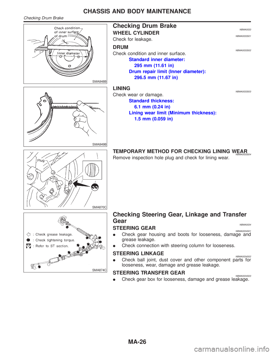
SMA848B
Checking Drum BrakeNBMA0033WHEEL CYLINDERNBMA0033S01Check for leakage.
DRUMNBMA0033S02Check condition and inner surface.
Standard inner diameter:
295 mm (11.61 in)
Drum repair limit (Inner diameter):
296.5 mm (11.67 in)
SMA849B
LININGNBMA0033S03Check wear or damage.
Standard thickness:
6.1 mm (0.24 in)
Lining wear limit (Minimum thickness):
1.5 mm (0.059 in)
SMA870C
TEMPORARY METHOD FOR CHECKING LINING WEARNBMA0033S04Remove inspection hole plug and check for lining wear.
SMA874C
Checking Steering Gear, Linkage and Transfer
Gear
NBMA0034STEERING GEARNBMA0034S01ICheck gear housing and boots for looseness, damage and
grease leakage.
ICheck connection with steering column for looseness.
STEERING LINKAGENBMA0034S02ICheck ball joint, dust cover and other component parts for
looseness, wear, damage and grease leakage.
STEERING TRANSFER GEARNBMA0034S03ICheck gear box for looseness, damage and grease leakage.
CHASSIS AND BODY MAINTENANCE
Checking Drum Brake
MA-26
Page 2022 of 2395

SST280B
Checking Power Steering Fluid and LinesNBMA0035CHECKING FLUID LEVELNBMA0035S01ICheck fluid level with engine off.
ICheck fluid level with dipstick on reservoir cap. Use ªHOTº
range at fluid temperatures of 50 to 80ÉC (122 to 176ÉF). Use
ªCOLDº range at fluid temperatures of 0 to 30ÉC (32 to 86ÉF).
CAUTION:
IDo not overfill.
IRecommended fluid is Genuine NISSAN PSF II or equiva-
lent. Refer to ªRECOMMENDED FLUIDS AND
LUBRICANTSº, MA-11.
SST118B
CHECKING LINESNBMA0035S02ICheck lines for improper attachment, leaks, cracks, damage,
loose connections, chafing and deterioration.
ICheck rack boots for accumulation of power steering fluid.
Lubricating Locks, Hinges and Hood LatchesNBMA0036
SMA897C
GI
EM
LC
EC
FE
AT
TF
PD
AX
SU
BR
ST
RS
BT
HA
SC
EL
IDX
CHASSIS AND BODY MAINTENANCE
Checking Power Steering Fluid and Lines
MA-27
Page 2023 of 2395

Checking Seat Belts, Buckles, Retractors,
Anchors and Adjusters
NBMA0037
SMA854CE
CHASSIS AND BODY MAINTENANCE
Checking Seat Belts, Buckles, Retractors, Anchors and Adjusters
MA-28
Page 2024 of 2395

Engine Maintenance
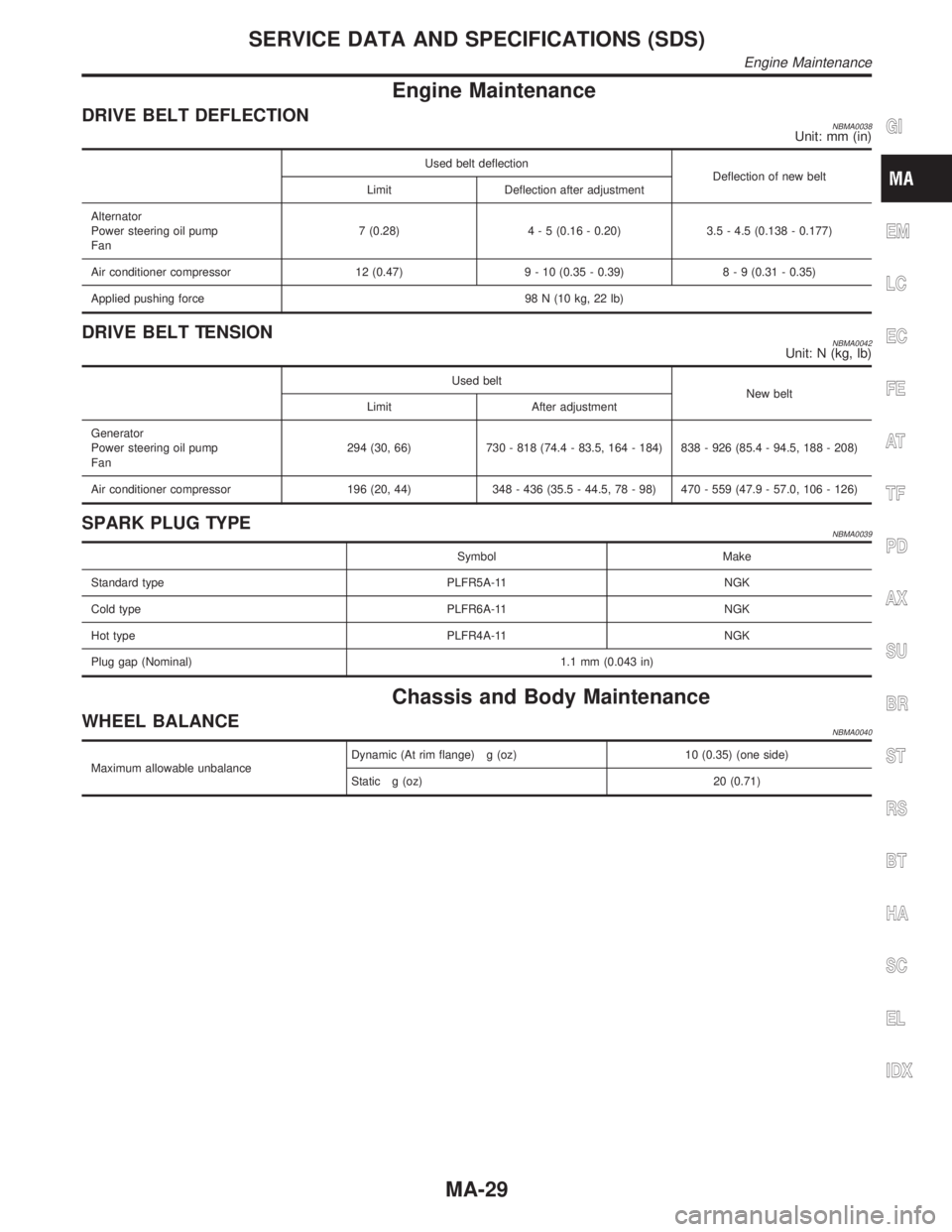
DRIVE BELT DEFLECTIONNBMA0038Unit: mm (in)
Used belt deflection
Deflection of new belt
Limit Deflection after adjustment
Alternator
Power steering oil pump
Fan7 (0.28)4 - 5 (0.16 - 0.20) 3.5 - 4.5 (0.138 - 0.177)
Air conditioner compressor 12 (0.47) 9 - 10 (0.35 - 0.39)8 - 9 (0.31 - 0.35)
Applied pushing force 98 N (10 kg, 22 lb)
DRIVE BELT TENSIONNBMA0042Unit: N (kg, lb)
Used belt
New belt
Limit After adjustment
Generator
Power steering oil pump
Fan294 (30, 66) 730 - 818 (74.4 - 83.5, 164 - 184) 838 - 926 (85.4 - 94.5, 188 - 208)
Air conditioner compressor 196 (20, 44) 348 - 436 (35.5 - 44.5, 78 - 98) 470 - 559 (47.9 - 57.0, 106 - 126)
SPARK PLUG TYPENBMA0039
Symbol Make
Standard type PLFR5A-11 NGK
Cold type PLFR6A-11 NGK
Hot type PLFR4A-11 NGK
Plug gap (Nominal) 1.1 mm (0.043 in)
Chassis and Body Maintenance
WHEEL BALANCENBMA0040
Maximum allowable unbalanceDynamic (At rim flange) g (oz) 10 (0.35) (one side)
Static g (oz) 20 (0.71)
GI
EM
LC
EC
FE
AT
TF
PD
AX
SU
BR
ST
RS
BT
HA
SC
EL
IDX
SERVICE DATA AND SPECIFICATIONS (SDS)
Engine Maintenance
MA-29
Page 2025 of 2395

NOTES
Page 2026 of 2395

PROPELLER SHAFT &
DIFFERENTIAL CARRIER
SECTION
PD
CONTENTS
PROPELLER SHAFT......................................................3
Noise, Vibration and Harshness (NVH)
Troubleshooting ...........................................................3
NVH TROUBLESHOOTING CHART............................3
Components.................................................................4
FRONT PROPELLER SHAFT.....................................4
REAR PROPELLER SHAFT.......................................5
On-vehicle Service.......................................................6
PROPELLER SHAFT VIBRATION...............................6
APPEARANCE CHECKING........................................6
Removal and Installation .............................................6
Inspection.....................................................................7
Disassembly.................................................................7
CENTER BEARING - 2WD -.......................................7
JOURNAL (71H AND 80B)..........................................8
Assembly .....................................................................9
CENTER BEARING - 2WD -.......................................9
JOURNAL (71H AND 80B)..........................................9
Service Data and Specifications (SDS)..................... 11
GENERAL SPECIFICATIONS................................... 11
SERVICE DATA....................................................... 11
SNAP RING (80B).................................................... 11
SNAP RING (71H)...................................................12
R200A
FRONT FINAL DRIVE...................................................13
Preparation ................................................................13
SPECIAL SERVICE TOOLS......................................13
Noise, Vibration and Harshness (NVH)
Troubleshooting .........................................................15
On-vehicle Service.....................................................15
FRONT OIL SEAL REPLACEMENT...........................15
REAR COVER GASKET REPLACEMENT..................16
Components...............................................................17
Removal and Installation ...........................................18
REMOVAL...............................................................18
INSTALLATION........................................................18
Disassembly...............................................................18
PRE-INSPECTION...................................................18
FINAL DRIVE HOUSING..........................................19
DIFFERENTIAL CASE..............................................21
DIFFERENTIAL SIDE SHAFT...................................22
Inspection...................................................................23
RING GEAR AND DRIVE PINION.............................23
DIFFERENTIAL CASE ASSEMBLY...........................23
BEARING................................................................23
Adjustment .................................................................24
SIDE BEARING PRELOAD.......................................24
PINION GEAR HEIGHT AND PINION BEARING
PRELOAD
...............................................................25
TOOTH CONTACT...................................................29
Assembly ...................................................................30
DIFFERENTIAL SIDE SHAFT...................................30
DIFFERENTIAL CASE..............................................31
FINAL DRIVE HOUSING..........................................32
Service Data and Specifications (SDS).....................36
R200A.....................................................................36
H233B
REAR FINAL DRIVE.....................................................38
Preparation ................................................................38
SPECIAL SERVICE TOOLS......................................38
Noise, Vibration and Harshness (NVH)
Troubleshooting .........................................................40
On-vehicle Service.....................................................40
FRONT OIL SEAL REPLACEMENT...........................40
Components...............................................................42
Removal and Installation ...........................................43
REMOVAL...............................................................43
INSTALLATION........................................................43
Disassembly...............................................................43
PRE-INSPECTION...................................................43
DIFFERENTIAL CARRIER........................................44
DIFFERENTIAL CASE..............................................46
Inspection...................................................................47
RING GEAR AND DRIVE PINION.............................47
DIFFERENTIAL CASE ASSEMBLY...........................47
BEARING................................................................47
Limited Slip Differential ..............................................47
PREPARATION FOR DISASSEMBLY........................47
GI
MA
EM
LC
EC
FE
AT
TF
AX
SU
BR
ST
RS
BT
HA
SC
EL
IDX
Page 2027 of 2395

DISASSEMBLY........................................................48
INSPECTION...........................................................49
ADJUSTMENT.........................................................50
ASSEMBLY.............................................................51
Adjustment .................................................................53
PINION GEAR HEIGHT............................................53
TOOTH CONTACT...................................................56Assembly ...................................................................57
DIFFERENTIAL CASE..............................................57
DIFFERENTIAL CARRIER........................................58
Service Data and Specifications (SDS).....................62
H233B.....................................................................62
CONTENTS(Cont'd)
PD-2
Page 2028 of 2395

Noise, Vibration and Harshness (NVH)
Troubleshooting
=NBPD0049NVH TROUBLESHOOTING CHARTNBPD0049S01Use the chart below to help you find the cause of the symptom. If necessary, repair or replace these parts.
Reference pageÐ
Ð
Ð
Ð
PD-6
PD-6
PD-23, 47
PD-29, 56
PD-23, 47
PD-18, 43
Ð
Ð
Ð
Ð
AX-3
AX-3
SU-3
SU-3
SU-3
BR-6
ST-6
Possible cause and
SUSPECTED PARTS
Uneven rotation torque
Excessive center bearing axial end play
Center bearing mounting (insulator) cracks, damage or deterioration
Excessive joint angle
Rotation imbalance
Excessive runout
Rough gear tooth
Improper gear contact
Tooth surfaces worn
Incorrect backlash
Companion flange excessive runout
Improper gear oil
PROPELLER SHAFT
DIFFERENTIAL
DRIVE SHAFT
AXLE
SUSPENSION
TIRES
ROAD WHEEL
BRAKES
STEERING
SymptomPROPEL-
LER
SHAFTNoise´´´´´´ ´´´´´´´´
Shake´ ´´´´´´´
Vibration´´´´´´ ´´´´ ´
DIFFER-
ENTIALNoise´´´´´´´ ´´´´´´´
´: Applicable
GI
MA
EM
LC
EC
FE
AT
TF
AX
SU
BR
ST
RS
BT
HA
SC
EL
IDX
PROPELLER SHAFT
Noise, Vibration and Harshness (NVH) Troubleshooting
PD-3
Page 2029 of 2395

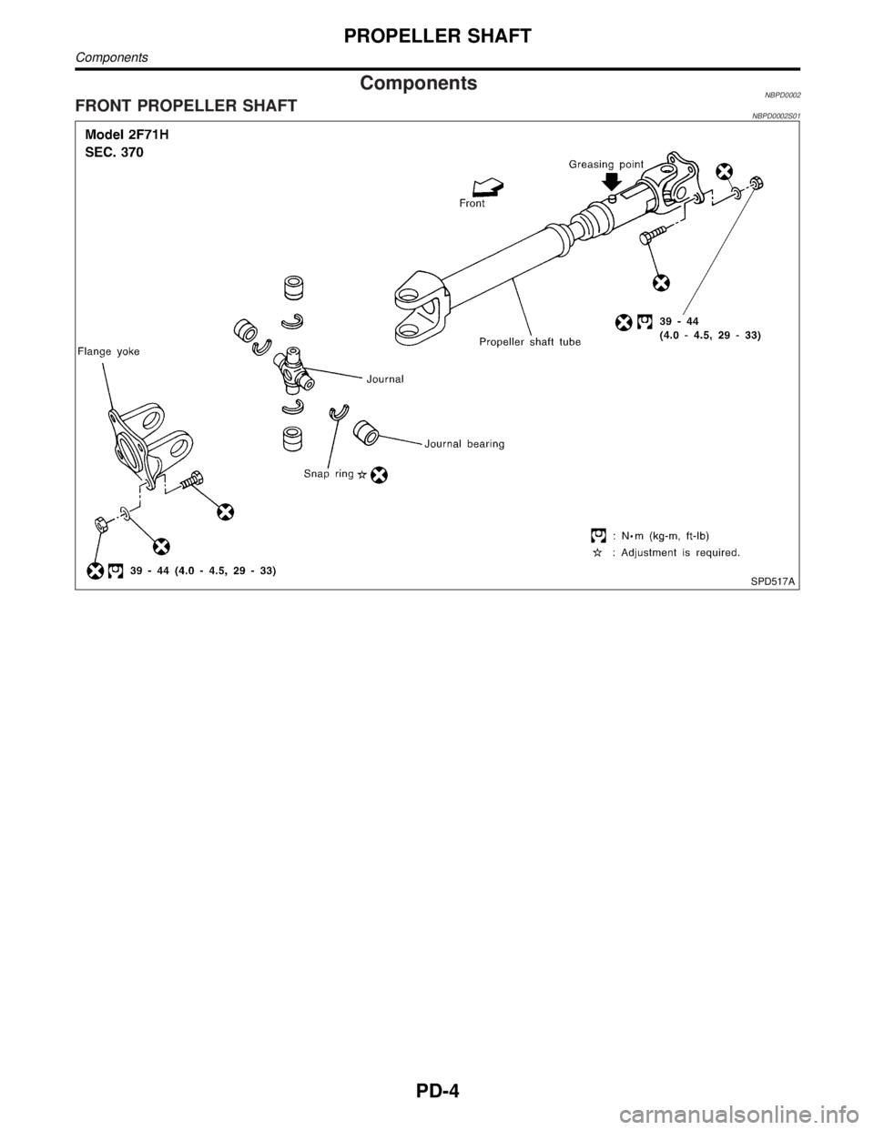
ComponentsNBPD0002FRONT PROPELLER SHAFTNBPD0002S01
SPD517A
PROPELLER SHAFT
Components
PD-4
Page 2030 of 2395

REAR PROPELLER SHAFTNBPD0002S02
SPD522A
SPD468AA
GI
MA
EM
LC
EC
FE
AT
TF
AX
SU
BR
ST
RS
BT
HA
SC
EL
IDX
PROPELLER SHAFT
Components (Cont'd)
PD-5